7
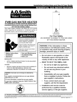
Combustion Air Inlet
Openings
Installing the water heater.
This water heater must be installed in accordance with these instructions, local codes, utility company
requirements, and/or in the absence of local codes, use the latest edition of the American National
Standard/National Fuel Gas Code. A copy can be purchased from either the American Gas Association,
400 N. Capitol Street NW, Washington, DC 20001 as ANSI standard Z223.1 or National Fire Protection
Association, 1 Batterymarch Park, Quincy, MA 02269 as booklet NFPA 54.
Location
The water heater should not be located
in an area where leakage from the tank
or connections will result in damage
to the area adjacent to the heater or to
lower floors of the structure.
When such areas cannot be avoided it is
recommended that a suitable drain pan,
adequately drained, must be installed
under the water heater.
The drain pan must not restrict air
flow to the combustion air inlet openings
(perforation openings) located around the
lower perimeter of the water heater.
Drain pan kits are available from the store
where the water heater was purchased, or
any water heater distributor.
Make certain the floor underneath
the water heater is strong enough to
sufficiently support the weight of the
water heater once it is filled with water.
A gas fired water heater or any other
appliance should not be installed in
a space where liquids which give off
flammable vapors are to be used or stored.
Such liquids include gasoline, LP gas
(butane or propane), paint or adhesives
and their thinners, solvents or removers.
When installed in a closet, DO NOT
block or obstruct any of the combustion
air inlet openings located around the
perimeter of the water heater. A
minimum of 1” is required between
these combustion air inlet openings and
any obstruction.
Because of natural air movement in a
room or other enclosed space, flammable
vapors can be carried some distance from
where liquids which give off flammable
vapors are to be used or stored. The open
flame of the water heater’s pilot or main
burner can ignite these vapors and create a
shut down condition of the water heater
which will not allow the water heater
to ignite until examined by a Qualified
Service Technician.
FVIR certified gas water heaters can be
installed on a residential garage floor
without the use of an 18-inch stand in
accordance with the National Fuel Gas
Code, NFPA 54, ANSI Z223.1, unless
otherwise directed by State and Local
code requirements. The water heater must
be located so it is not subject to physical
damage, for example, by moving vehicles,
area flooding, etc
● The water heater should be installed
as close as practical to the gas vent or
chimney.
● Long hot water lines should be insulated
to conserve water and energy.
● The water heater and water lines should
be protected from exposure to freezing
temperatures.
● DO NOT install the water heater in
bathrooms, bedrooms, any occupied
rooms normally kept closed, or in
unprotected outdoor areas.
● Minimum clearance from combustible
construction:
If the clearances stated on the
Instruction/Warning Label, located on
the front of the heater differ, install the
water heater according to the clearances
stated on the label.
● If the water heater is installed in an
alcove or closet, the entire floor must
be covered by a wood or metal panel.
A minimum of 24” clearance from the
front and top should be available for
adequate inspection and servicing.
● The water heater may be installed on
combustible floors, but not directly on
carpeting. If the water heater must be
installed on carpeting, place a metal or
wood panel beneath the water heater,
extending beyond its full width and
depth at least 3” in all directions.
The auxiliary drain pan
installation MUST conform
to local codes.
Diameter of
water heater
plus 2” min.
Max.
2”
WARNING: Combustible
construction refers to
adjacent walls and ceilings
and should not be confused
with combustible or
flammable products and
materials. Combustible
and/or flammable products
and materials should never
be stored in the vicinity of
this or any gas appliance.
Location Front Sides Rear Top
Alcove
3”
(7.6 cm)
0”
(0 cm)
0”
(0 cm)
12”
(30.5 cm)
Closet
3”
(7.6 cm)
1”
(2.5 cm)
0”
(0 cm)
12”
(30.5 cm)