Epson EL 33 User manual
- Category
- PC/workstation barebones
- Type
- User manual
This manual is also suitable for

EPSON
®
EL 4S/33
User’s Guide
@
This manual is printed on recycled paper and is 100% recyclable.

IMPORTANT NOTICE
DISCLAIMER OF WARRANTY
Epson America makes no representations or warranties, either express or implied, by or
with respect to anything in this manual, and shah not be liable for any implied warranties
of merchantability and fitness for a particular purpose or for any indirect, special, or
consequential damages. Some states do not allow the exclusion of incidental or
consequential damages, so this exclusion may not apply to you.
COPYRIGHT NOTICE
All rights reserved. No part of this publication may be reproduced, stored in a retrieval
system, or transmitted, in any form or by any means, electronic, mechanical,
photocopying, recording, or otherwise,
without the prior written permission of Epson
America, Inc. No patent liability is assumed with respect to the use of information
contained herein. Nor is any liability assumed for damages resulting from the use of the
information contained herein Further, this publication and features described herein are
subject to change without notice.
TRADEMARKS
Epson is a registered trademark of Seiko Epson Corporation
General notice: Other product names used herein are for identification purposes only and
may be trademarks of their respective companies.
Copyright
0
1993 by Epson America, Inc.
400251400
Torrance, California, USA
8/93
ii

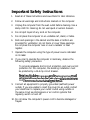
Important Safety Instructions
1.
2.
3.
4.
5.
6.
7.
8.
9.
Read all of these instructions and save them for later reference.
Follow all warnings and instructions marked on the computer.
Unplug the computer from the wall outlet before cleaning. Use a
damp cloth for cleaning; do not use liquid or aerosol cleaners.
Do not spill liquid of any kind on the computer.
Do not place the computer on an unstable cart, stand, or table.
Slots and openings in the cabinet and the back or bottom are
provided for ventilation; do not block or cover these openings.
Do not place the computer near or over a radiator or heat
register.
Operate the computer using the type of power source indicated
on its label.
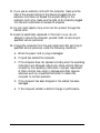
If you plan to operate the computer in Germany, observe the
following safety precaution:
To provide adequate short-circuit protection and over-current
protection for this computer, the building installation must
be protected by a 16 Amp circuit breaker.
Beim
AnschluB
des
Computers
an
die
Netzversorgung
mui
sichergestellt
werden,
dai3
die
Gebaudeinstallation
mit
einem
16 A
Uberstromschutzschalter
abgesichert
ist.
Connect all equipment to properly grounded (earthed) power
outlets. If you are unable to insert the plug into an outlet, contact
your electrician to replace your outlet. Avoid using outlets on
the same circuit as photocopiers or air control systems that
regularly switch on and off.
10. Do not allow the computer’s power cord to become damaged or
frayed.
iii

11. If you use an extension cord with the computer, make sure the
total of the ampere ratings of the devices plugged into the
extension cord does not exceed the ampere rating for the
extension cord. Also, make sure the total of all products plugged
into the wall outlet does not exceed 15 amperes.
12. Do not insert objects of any kind into this product through the
cabinet slots.
13. Except as specifically explained in this User’s
Guide,
do not
attempt to service the computer yourself. Refer all servicing to
qualified service personnel.
14. Unplug the computer from the wall outlet and refer servicing to
qualified service personnel under the following conditions:
A.
B.
C.
D.
E.
When the power cord or plug is damaged.
If liquid has entered the computer.
If the computer does not operate normally when the operating
instructions are followed. Adjust only those controls that are
covered by the operating instructions. Improper adjustment
of other controls may result in damage and often requires
extensive work by a qualified technician to restore the
computer to normal operation.
If the computer has been dropped or the cabinet has been
damaged.
If the computer exhibits a distinct change in performance.
iv
Page is loading ...
Page is loading ...

FCC COMPLIANCE STATEMENT
FOR AMERICAN USERS
This equipment has been tested and found to comply with the limits for a class B digital
device, pursuant to Part 15 of the FCC Rules. These limits are designed to provide
reasonable protection against harmful interference in a residential installation. This
equipment generates, uses, and can radiate radio frequency energy and, if not installed
and used in accordance with the instructions, may cause harmful interference to radio and
television reception However, there is no guarantee that interference will not occur in a
particular installation If this equipment does cause interference to radio and television
reception, which can be determined by turning the equipment off and on, the user is
encouraged to try to correct the interference by one or more of the following measures:
0
Reorient or relocate the receiving antenna
0
Increase the separation between the equipment and receiver
0
Connect the equipment into an outlet on a circuit different from that to which the
receiver is connected
Cl
Consult an experienced radio/TV technician for help.
WARNING
The connection of a non-shielded equipment interface cable to this equipment will
invalidate the FCC Certification of this device and may cause interference levels that
exceed the limits established by the FCC for this equipment. It is the responsibility of the
user to obtain and use a shielded equipment interface cable with this device. If this
equipment has more than one interface connector, do not leave cables connected to unused
interfaces.
Changes or modifications not expressly approved by the manufacturer could void the
user’s authority to operate the equipment
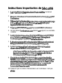
FOR CANADlAN USERS
This digital apparatus does not exceed the Class B limits for radio noise emissions from
digital apparatus as set out in the radio interference regulations of the Canadian
Department of Communications.
Le
present
appareil
num&ique
n’&net
pas
de
bruits
radioelectriques
d&passant
les
limites
appliables
aux
appareils
numeriques
de
Classe
B
prescrites
dans
le
r&glement
sur
le
brouillage
radio6lectrique
6dicte
par
le
Minist&re
des
Communications
du
Canada.

Contents
VGA Utilities
.............................
2
Optional Equipment
........................
2
Memory
.............................
2
Drives
..............................
2
Math Coprocessor
.......................
3
How to Use This Manual
......................
3
Chapter 1
Setting Up Your System
Getting Started
............................
1-1
Choosing a Location
......................
1-1
Unpacking Your Computer
.................
1-2
Connecting the Computer
.....................
1-3
Connecting a Keyboard
....................
1-4
Connecting a Mouse
......................
1-4
Connecting a Monitor
.....................
1-4
Connecting a Printer or Other Device
............
1-5
Using the Parallel Port
....................
1-5
Using the Serial Ports
.....................
1-6
Connecting the Power Cord
.................
1-6
Turning On the Computer
..................
1-7
Running the SETUP Program
...................
1-8
Starting the SETUP Program
.................
1-8
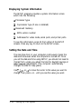
Displaying System Information
...............
1-10
Setting the Date and Time
..................
1-10
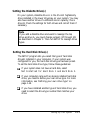
Setting the Diskette Drive(s)
.................
1-11
Setting the Hard Disk Drive(s)
................
1-11
Checking System Memory
..................
1-15
Setting the Video Display Type
...............
1-15
Setting Keyboard Options
..................
1-16
Setting the Processor Speed
..................
1-16
Cyrix Cache Option
......................
1-16
Setting Chip Set Feature Control Options
.........
1-17
Exiting the SETUP Program
.................
1-18
Post-SETUP Procedures
......................
1-18
vii

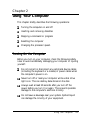
Chapter 2
Using Your Computer
Turning On the Computer
......................
2-1
Turning Off the Computer
......................
2-3
Inserting and Removing Disks
...................
2-4
Stopping a Command or Program
.................
2-5
Resetting the Computer
.......................
2-5
Changing the Processor Speed
...................
2-6
Chapter 3
Installing and Removing Options
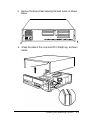
Removing and Replacing the Cover
................
3-2
Locating the Internal Components
.................
3-5
Changing the Jumper Settings
...................
3-6
Setting the Jumpers
.......................
3-8
Installing Memory Modules (SIMMs)
...............
3-9
Inserting SIMMs
.........................
3-10
Removing SIMMs
........................
3-12
Installing an Option Card
......................
3-13
Removing an Option Card
......................
3-16
Adding Video Memory
.......................
3-16
Installing the Math Coprocessor
..................
3-19
Post-installation Procedures
.....................
3-20
Chapter 4
Installing and Removing Drives
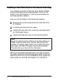
Installing a Hard Disk Drive in the Internal Drive Bay
. . . . . 4-2
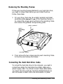
Removing the Mounting Frames . . . . . . . . . . . . . . . 4-3
Connecting the Hard Disk Drive Cable. . . . . . . . . . . . 4-3
Connecting the Drive Cable to the System Board . . . . . . 4-4
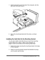
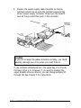
Connecting the Drive and Power Cables to the Drive
. . . 4-5
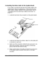
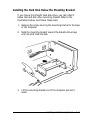
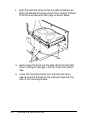
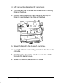
Installing the Hard Disk Below the Mounting Bracket . . . 4-7
Installing the Hard Disk On the Mounting Bracket . . . . . 4-9
Removing a Hard Disk Drive From the Internal Drive Bay
. . . 4-11
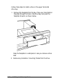
Installing a Drive in the Upper Horizontal Drive Bay
. . . . . . 4-11
Connecting the Drive and Power Cables . . . . . . . . . . . 4-14
Removing a Drive from the Upper Drive Bay . . . . . . . . . . . 4-17
Post-installation Procedures . . . . . . . . . . . . . . . . . . . . . 4-17
viii

Chapter 5 Installing
Video
Drivers
Installing the Drivers
........................
5-2
Lotus 1-2-3 or Symphony
......................
5-3
Microsoft Windows
.........................
5-4
Microsoft Word
...........................
5-5
Quattro Pro
..............................
5-6
WordPerfect
.............................
5-7
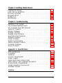
Chapter 6 Troubleshooting
Identifying Your System
......................
6-1
The Computer Will Not Start
...................
6-2
The Computer Does Not Respond
................
6-3
Keyboard Problems
.........................
6-4
Monitor Problems
..........................
6-4
Diskette Problems
..........................
6-6
Diskette Drive Problems
......................
6-7
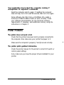
Hard Disk Drive Problems
.....................
6-7
Software Problems
.........................
6-8
Printer Problems
...........................
6-9
Option Card Problems
.......................
6-9
Memory Module Problems
.....................
6-10
Controller Problems
.........................
6-11
Mouse Problems
...........................
6-11
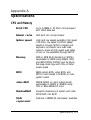
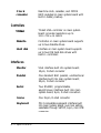
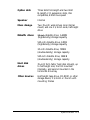
Appendix A Specifications
CPU and Memory
..........................
A-1
Controllers
..............................
A-2
Interfaces
...............................
A-2
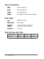
Physical Characteristics
.......................
A-4
Power Supply.
............................
A-4
Option Slot Power Limits (Total)
..................
A-4
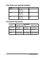
Video Memory and Supported Resolutions
...........
A-5
Environmental Requirements
...................
A-5
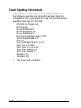
Tested Operating Environments
..................
A-6
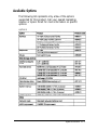
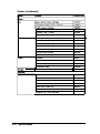
Available Options
..........................
A-7
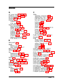
Index
ix

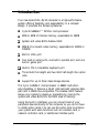
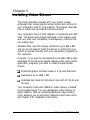
Introduction
Your new Epson® EL 4S/33 computer is a high-performance
system offering flexibility and expandability in a compact
design. It provides the following features:
0
Cl
0
0
0
0
cl
0
0
Cyrix® Cx486SLC™ 33 MHz microprocessor
2MB or 4MB of internal memory, expandable to 16MB
System and video BIOS shadow RAM
256KB of on-board video memory, expandable to 512KB or
1024KB
Built-in VGA port
Two built-in serial ports, one built-in parallel port, and one
built-in game port
Built-in PS/2 compatible keyboard port
Three 16-bit full-length and two 8-bit half-length ISA option
slots
Support for up to three mass storage devices.
The Cyrix Cx4S6SLC microprocessor is 486SX instruction
set-compatible. It features a 32-bit internal/l&bit external data
path and is 3S6SX bus-compatible. The shadow RAM feature
allows your system to speed up processing by moving the
system and video BIOS into the RAM area of memory.
Using the built-in interfaces, you can connect most of your
peripheral devices directly to the computer so you do not have
to install option cards. You can use the option slots to enhance
your system with extra functions such as a modem card, a
network controller card, or additional interface ports.
Introduction 1

The VGA controller supports standard resolutions up to
640 x 480 in 16 colors and extended resolutions up to 1024 x 768
in 4 colors (interlaced or non-interlaced). With 512KB video
memory, the controller supports resolutions up to 1024 x 768 in
16 colors; with 1024KB, it supports the same resolutions in up
to 256 colors.
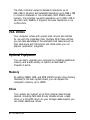
VGA Utilities
Your computer comes with special VGA drivers and utilities
for use with the integrated VGA interface. With these utilities,
you can take advantage of the extended VGA features such as
high resolutions and 132-column text mode when you run
popular application programs.
Optional Equipment
You can easily upgrade your computer by installing additional
memory and a wide variety of options as described in
Chapters 3 and 4.
Memory
By adding 256KB, 1MB, and 4MB SIMMs (single inline memory
modules) to the main system board, you can expand the
computer’s memory up to 16MB.
Drives
Your system can support up to three internal mass storage
devices, including hard disk drives, diskette drives, a tape
drive, or a CD-ROM drive. As your storage needs expand, you
can install additional drives.
2 Introduction

Math Coprocessor
You may want to install a Cyrix Cx83S87-33 coprocessor. This
optional math coprocessor allows your computer to perform
mathematical functions faster.
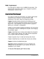
How to Use This Manual
This manual contains the information you need to get the best
results from your computer. You do not have to read
everything in this book; check the following summary.
Chapter 1
provides simple instructions for setting up your
system and connecting peripheral devices such as the monitor
and printer. It also describes running the SETUP program to
define your computer’s configuration.
Chapter 2 covers general operating procedures, such as turning
the computer on and off, resetting the computer, and changing
the processor speed.
Chapter
3 describes how to remove and replace the computer’s
cover, change jumper settings, and install optional equipment
such as option cards and memory modules.
Chapter 4 explains how to install and remove disk drives.
Chapter 5 describes how to install VGA drivers and utilities.
Chapter
6 contains troubleshooting tips.
Appendix A
lists the specifications of your computer, the
software that has been tested on your system, and options
available for your system.
At
the end of this manual you’ll find an Index.
Introduction 3

Chapter 1
Setting Up Your System
This chapter briefly describes the operations you will use to set
up your computer. It includes the following information:
0
Getting started
Q
Connecting the computer
0
Running the SETUP program
0
Post-SETUP procedures.
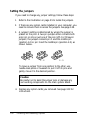
Getting Started
Follow the instructions below for choosing a location for your
new system, unpacking your system, and setting up your
computer.
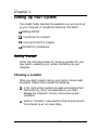
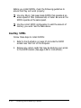
Choosing a Location
When you select a place to set up your system, choose a safe,
convenient location that provides the following:
0
A flat, hard surface. Surfaces like beds and carpets attract
static electricity, which can erase data on your disks,
damage the computer’s circuitry, and prevent proper
ventilation.
P
Good air circulation. Leave several inches of space around
the computer so air can move freely.
Setting Up Your System
1-1

cl
0
P
Moderate environmental conditions. Select a cool, dry area
and protect your computer from extremes in temperature,
humidity, dust, and smoke. Avoid direct sunlight or other
sources of heat.
No electromagnetic interference. Do not place your system
too close to any electrical device, such as a telephone or
television, which generates an electromagnetic field.
Appropriate power source. Connect all your equipment
with the appropriate power cords for the power source in
your area.
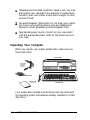
Unpacking Your Computer
When you unpack your system components, make sure you
have these items:
diskettes
computer
keyboard
Your system also includes a serial mouse and may come with
the operating system and software already installed on a hard
disk drive.
1-2
Setting Up Your System

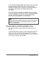
If you purchased any optional equipment that goes inside the
computer--such as option cards, memory modules, a hard
disk, or a diskette drive-you should install these devices
before you connect your computer. See Chapters 3 and 4 for
instructions.
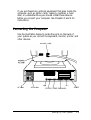
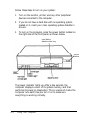
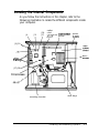
Connecting the Computer
Use the illustration below to locate the ports on the back of
your system as you connect the keyboard, monitor, printer, and
other devices.
monitor cable
AC inlet AC outlet
COM1 COM2 PARALLEL
GAME
Setting Up Your System
1-3

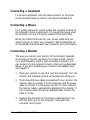
Connecting a Keyboard
To connect a keyboard, hold the cable connector so the arrow
on the connector faces up. Insert it into the port marked K/B.
Connecting a Mouse
Your system came with a serial mouse that connects to either of
the computer’s built-in serial ports. To connect the mouse, insert
the connector into one of the ports marked COM1 and COM2.
When you install the drivers for your mouse, make sure you
identify the port to which you connected it. See the README file
on the diskette that came with your mouse for more information.
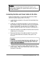
Connecting a Monitor
The way you connect your monitor to the computer depends
on the type of monitor you have. If you have a VGA monitor
(or a multifrequency monitor with an analog connector), you
can connect it to the computer’s built-in VGA port as described
below. If you are connecting your monitor to an adapter card,
see Chapter 3.
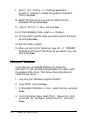
1.
Place your monitor on top of or near the computer. Turn the
monitor and computer around so the backs are facing you.
2.
There should be two cables provided with your monitor: the
monitor cable (to connect it to the computer) and the power
cable (to connect it to the power source). On most monitors,
the monitor cable is permanently attached to the monitor. If
your monitor does not have an attached cable, connect the
cable to it now.
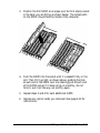
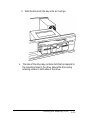
3.
Examine the connector on the monitor cable and line it up
with the VGA port on the computer. Then insert the
connector into the port.
1-4
Setting Up Your System

caution
To avoid damaging the connector, be careful not to bend
the
pins when you insert it.
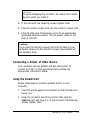
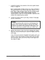
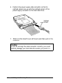
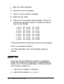
4.
If the connector has retaining screws, tighten them.
5.
Plug the monitor power cord into the monitor’s power inlet.
6. Plug the other end of the power cord into an appropriate
grounded electrical outlet or into the power outlet on the
back of the CPU.
Caution
If you plug the monitor’s power cord into the back of your
computer, make sure the monitor’s power requirements do
not exceed 1 Amp.
Connecting a Printer of Other Device
Your computer has one parallel and two serial ports. To
connect a printer or other peripheral device, follow the
appropriate instructions below.
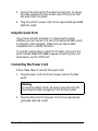
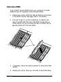
Using the Parallel Port
Follow these steps to connect a parallel printer to your
computer:
1.
Place the printer
next
to the computer so that the backs are
facing you.
2.
Align the connector end of the printer cable with the
PARALLEL
port and plug it in. If the connector has retaining
screws, tighten them.
Setting Up Your System
1-5

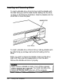
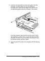
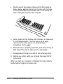
3.
Connect the other end of the cable to the printer. To secure
the cable, squeeze the clips at each side of the printer port
and push them into place.
4. Plug the printer’s power cord into an appropriate grounded
electrical outlet.
Using the Serial Ports
If you have a printer, a modem, or a mouse with a serial
interface, you can connect it to one of the serial (RS-232C) ports
on the back of the computer. Make sure you have a cable
compatible with a DB-9P connector.
To connect a serial device, insert the connector into one of the
ports marked
COM1
and
COM2. If you are
connecting only one
serial device, use the COM1 port.
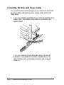
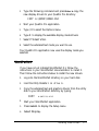
Connecting the Power Cord
Follow these steps to connect the power cord:
1.
Plug the power cord into the AC power inlet on the back
panel.
Warning
To avoid an electric shock, be sure to plug the cord into
the computer before plugging it into the wall outlet.
2.
Plug the other end of the power cord into an appropriate
grounded electrical outlet.
1-6
Setting Up Your System

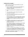
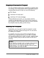
Turning On the Computer
After you set up your system, you are ready to turn on the
power. Follow these steps:
1.
Turn your computer around so the front panel faces you.
Place your monitor, printer, and other devices in a
convenient arrangement.
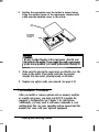
2. If there is a protective card in the diskette drive, remove it
now.
3.
Turn on the monitor, printer, and any other devices
connected to the computer.
4. Turn on the computer by pressing the power button on the
right side of the front panel.
The screen displays a count of the system memory, and then
the computer performs its power-on diagnostics, which are
a series of checks that make sure everything is working
correctly.
5. If necessary, use the controls on your monitor to adjust the
brightness and contrast until you can easily see the
characters on the screen.
If your system is configured to automatically load a program
(such as Microsoft Windows or a word processing
program), you see the first menu or screen display of that
program. If not, you may see the operating system prompt,
such as C:\> or A:\>.
If there is no operating system installed on your computer,
you see an error message. Ignore the message for now; once
you install the operating system, you will not see this message.
Now follow the instructions in the next section to configure
your system using the SETUP program.
Setting Up Your System
1-7

Running the SETUP Program
You need to run SETUP the first time you use your computer.
Even if your system was configured for you, you may still need
to set the date and time, and if your system came unconfigured,
you need to define how it is set up. (You also may need to run
SETUP again later if you change your configuration.)
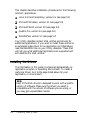
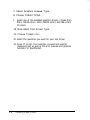
SETUP is stored in the computer’s ROM BIOS, so you can run it
any time. SETUP lets you verify or change the following:
Q
Current date and time
Cl
Type of diskette drive(s) and hard disk drive(s)
0
System memory
0
Type of video display adapter
0
Keyboard options
Ll
Processor speed
Q
Shadow options
Q
Processor chip features.
The configuration information is stored in an area of memory
called CMOS RAM. This memory is backed up by a battery, so
it is not erased when you turn off or reset the computer.
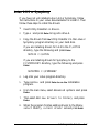
Starting the SETUP Program
You can run SETUP whenever you see the operating system
command prompt, such as:
C:\> or A:\>
To start SETUP, hold down Ctrl and Alt, then press S.
1-8
Setting Up Your System

Also, whenever you start your computer, if the system detects
an error in your system configuration, you will see the
following message:
Press the F1 key to continue, F2 to run the
setup utility
Press F2 to run the SETUP program to correct your
configuration.
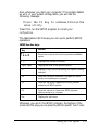
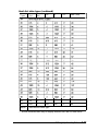
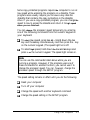
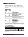
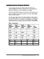
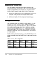
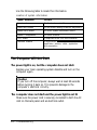
The table below lists the keys you can use to perform SETUP
operations.
SETUP function keys
Key
Function
t&t
+
Moves the cursor to the next or previous modifiable
option
l 4-
Changes the values in the field
PgDn PgU
P
Displays the next or the previous menu
F1
Displays a help screen describing the option currently
selected
F4
From the exit menu, saves the changes you have
made and restarts your computer
F5
From the exit menu, supplies the factory default
values for all SETUP options
F6
From the exit menu. leaves the SETUP program
without saving any changes
Esc
Displays the exit menu
Whenever you are in the SETUP program, the bottom of the
screen lists the keys you can press to perform specific
functions.
Setting Up Your System
1-9
Page is loading ...
Page is loading ...
Page is loading ...
Page is loading ...
Page is loading ...
Page is loading ...
Page is loading ...
Page is loading ...
Page is loading ...
Page is loading ...
Page is loading ...
Page is loading ...
Page is loading ...
Page is loading ...
Page is loading ...
Page is loading ...
Page is loading ...
Page is loading ...
Page is loading ...
Page is loading ...
Page is loading ...
Page is loading ...
Page is loading ...
Page is loading ...
Page is loading ...
Page is loading ...
Page is loading ...
Page is loading ...
Page is loading ...
Page is loading ...
Page is loading ...
Page is loading ...
Page is loading ...
Page is loading ...
Page is loading ...
Page is loading ...
Page is loading ...
Page is loading ...
Page is loading ...
Page is loading ...
Page is loading ...
Page is loading ...
Page is loading ...
Page is loading ...
Page is loading ...
Page is loading ...
Page is loading ...
Page is loading ...
Page is loading ...
Page is loading ...
Page is loading ...
Page is loading ...
Page is loading ...
Page is loading ...
Page is loading ...
Page is loading ...
Page is loading ...
Page is loading ...
Page is loading ...
Page is loading ...
Page is loading ...
Page is loading ...
Page is loading ...
Page is loading ...
Page is loading ...
Page is loading ...
Page is loading ...
Page is loading ...
Page is loading ...
Page is loading ...
Page is loading ...
Page is loading ...
Page is loading ...
Page is loading ...
Page is loading ...
Page is loading ...
Page is loading ...
Page is loading ...
Page is loading ...
Page is loading ...
Page is loading ...
Page is loading ...
Page is loading ...
Page is loading ...
Page is loading ...
Page is loading ...
Page is loading ...
Page is loading ...
Page is loading ...
Page is loading ...
Page is loading ...
Page is loading ...
Page is loading ...
-
 1
1
-
 2
2
-
 3
3
-
 4
4
-
 5
5
-
 6
6
-
 7
7
-
 8
8
-
 9
9
-
 10
10
-
 11
11
-
 12
12
-
 13
13
-
 14
14
-
 15
15
-
 16
16
-
 17
17
-
 18
18
-
 19
19
-
 20
20
-
 21
21
-
 22
22
-
 23
23
-
 24
24
-
 25
25
-
 26
26
-
 27
27
-
 28
28
-
 29
29
-
 30
30
-
 31
31
-
 32
32
-
 33
33
-
 34
34
-
 35
35
-
 36
36
-
 37
37
-
 38
38
-
 39
39
-
 40
40
-
 41
41
-
 42
42
-
 43
43
-
 44
44
-
 45
45
-
 46
46
-
 47
47
-
 48
48
-
 49
49
-
 50
50
-
 51
51
-
 52
52
-
 53
53
-
 54
54
-
 55
55
-
 56
56
-
 57
57
-
 58
58
-
 59
59
-
 60
60
-
 61
61
-
 62
62
-
 63
63
-
 64
64
-
 65
65
-
 66
66
-
 67
67
-
 68
68
-
 69
69
-
 70
70
-
 71
71
-
 72
72
-
 73
73
-
 74
74
-
 75
75
-
 76
76
-
 77
77
-
 78
78
-
 79
79
-
 80
80
-
 81
81
-
 82
82
-
 83
83
-
 84
84
-
 85
85
-
 86
86
-
 87
87
-
 88
88
-
 89
89
-
 90
90
-
 91
91
-
 92
92
-
 93
93
-
 94
94
-
 95
95
-
 96
96
-
 97
97
-
 98
98
-
 99
99
-
 100
100
-
 101
101
-
 102
102
-
 103
103
-
 104
104
-
 105
105
-
 106
106
-
 107
107
-
 108
108
-
 109
109
-
 110
110
-
 111
111
-
 112
112
-
 113
113
-
 114
114
-
 115
115


Epson EL 33 User manual
- Category
- PC/workstation barebones
- Type
- User manual
- This manual is also suitable for
Ask a question and I''ll find the answer in the document
Finding information in a document is now easier with AI
Related papers
-
Epson Endeavor 486C User manual
-
-
-
-
-
-
-
-
-
