Napoleon Fireplaces GD70PT-S User manual
- Category
- Fireplaces
- Type
- User manual
This manual is also suitable for

1
W415-0434 / C / 03.24.05
INSTALLER: THESE INSTRUCTIONS MUST BE CONVEYED TO AND REMAIN WITH THE HOMEOWNER.
Wolf Steel Ltd., 24 Napoleon Rd., Barrie, ON L4M 4Y8 Canada • (705)721-1212 • fax(705)722-6031
www.napoleonfireplaces.com • [email protected]
VENTED GAS FIREPLACE HEATER
DIRECT VENT MILLIVOLT SYSTEM
INSTALLATION AND OPERATION INSTRUCTIONS FOR:
NATURAL GAS MODEL
GD70NT-S
PROPANE GAS MODEL
GD70PT-S
CERTIFIED FOR CANADA AND UNITED STATES USING ANSI / CSA METHODS
CERTIFIED UNDER CANADIAN AND AMERICAN NATIONAL STANDARDS, CSA 2.33, ANSI Z21.88 FOR VENTED GAS FIREPLACE HEATERS
WARNING: If the information in these instructions is not followed exactly, a fire or
explosion may result causing property damage, personal injury or death.
FOR YOUR SAFETY
Do not store or use gasoline or other flammable vapours and liquids in the vicinity of
this or any other appliance.
WHAT TO DO IF YOU SMELL GAS:
• Do not try to light any appliance.
• Do not touch any electrical switch.
• Do not use any phone in your building.
• Immediately call your gas supplier from a
neighbor's phone. Follow the gas supplier's
instructions.
• If you cannot reach your gas supplier, call
the fire department.
Installation and service must be performed by a qualified installer, service agency
or the gas supplier.

2
W415-0434 / C / 03.24.05
PG2-5 INTRODUCTION
Warranty
Dimensions
General Instructions
General Information
Care of Glass & Plated Parts
5-10 VENTING
Vent lengths
Venting Specifications
Air Terminal Locations
11-15 INSTALLATION/FRAMING
Wall & Ceiling Protection
Using Flexible Vent Components
Fireplace Vent Connection
Using Rigid Vent Components
Restricting Vertical Vents
Gas Installation
Mobile Home Installation
Framing
Mantle Clearances and Enclosures
16-19 FINISHING
Door Installation
Door Opening and Closing
Louvre Installation
Log Shipping Bracket Removal
Decorative Panels
Charcoal Strips
Log Placement
Baffle Installation
Charcoal Embers
Accent Lite Replacement
20 BLOWER INSTALLATION
THERMODISC REPLACEMENT
21-22 OPERATION / MAINTENANCE
Operating Instructions
Maintenance
22 ADJUSTMENTS
Pilot Burner Adjustment
Venturi Adjustment
23-24 REPLACEMENTS
Ordering Replacement Parts
Replacement Parts
Terminal Kits
Vent Kits
Accessories
25-26 TROUBLE SHOOTING GUIDE
27 SERVICE HISTORY
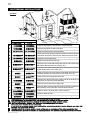
WARNING
• Do not burn wood or other materials in this fireplace.
• Adults and especially children should be alerted to the hazards of high surface temperatures and should stay away
to avoid burns or clothing ignition. Supervise young children when they are in the same room as the fireplace.
• Due to high temperatures, the fireplace should be located out of traffic and away from furniture and draperies.
• Clothing or other flammable material should not be placed on or near the fireplace.
• Any safety screen or guard removed for servicing must be replaced prior to operating the fireplace.
• It is imperative that the control compartments, burners and circulating blower and its passageway in the fireplace
and venting system are kept clean. The fireplace and its venting system should be inspected before use and at
least annually by a qualified service person. More frequent cleaning may be required due to excessive lint from
carpeting, bedding material, etc. The fireplace area must be kept clear and free from combustible materials,
gasoline and other flammable vapours and liquids.
• Under no circumstances should this fireplace be modified.
• This fireplace must not be connected to a chimney flue pipe serving a separate solid fuel burning appliance.
• Do not use this fireplace if any part has been under water. Immediately call a qualified service technician to inspect
the fireplace and to replace any part of the control system and any gas control which has been under water.
• Do not operate the fireplace with the glass door removed, cracked or broken. Replacement of the glass should be
done by a licensed or qualified service person.
• Do not strike or slam shut the fireplace glass door.
• This fireplace uses and requires a fast acting thermocouple. Replace only with a fast acting thermocouple sup-
plied by Wolf Steel Ltd.
NOTE: Changes, other than editorial, are denoted by a vertical line in the margin.
TABLE of CONTENTS
PLEASE RETAIN THIS MANUAL FOR FUTURE REFERENCE

3
W415-0434 / C / 03.24.05
ALL SPECIFICATIONS AND DESIGNS ARE SUBJECT TO CHANGE WITHOUT PRIOR NOTICE DUE TO ON-GOING PRODUCT IMPROVEMENTS. NAPOLEON® IS A REGISTERED
TRADEMARK OF WOLF STEEL LTD. PATENTS U.S. 5.303.693.801 - CAN. 2.073.411, 2.082.915. © WOLF STEEL LTD.
NAPOLEON gas fireplaces are manufactured under the strict Standard of the world recognized
ISO 9001 : 2000 Quality Assurance Certificate.
NAPOLEON products are designed with superior components and materials, assembled by trained craftsmen
who take great pride in their work. The burner and valve assembly are leak and test-fired at a quality test
station. The complete fireplace is thoroughly inspected by a qualified technician before packaging to ensure that
you, the customer, receives the quality product that you expect from NAPOLEON.
NAPOLEON GAS FIREPLACE PRESIDENT'S LIFETIME LIMITED WARRANTY
The following materials and workmanship in your new napoleon gas fireplace are warranted against defects for as
long as you own the fireplace. This covers: combustion chamber, heat exchanger, stainless steel burner, PHAZER™
logs and embers, ceramic glass (thermal breakage only), gold plated parts against tarnishing, porcelainized enamelled
components and aluminum extrusion trims.
Electrical (110V and millivolt) components and wearable parts such as the blower, gas valve, thermal switch, switches,
wiring, remote control, ignitor, gasketing, and pilot assembly are covered and NAPOLEON will provide replacement
parts free of charge during the first year of the limited warranty. Light bulbs are not covered by this warranty.
Labour related to warranty repair is covered free of charge during the first year. Repair work, however, requires the
prior approval of an authorized company official. Labour costs to the account of NAPOLEON are based on a prede-
termined rate schedule and any repair work must be done through an authorized NAPOLEON dealer.
CONDITIONS AND LIMITATIONS
NAPOLEON warrants its products against manufacturing defects to the original purchaser only -- i.e., the individual or legal entity (registered
customer) whose name appears on the warranty registration card filed with NAPOLEON -- provided that the purchase was made through an authorized
NAPOLEON dealer and is subject to the following conditions and limitations:
This factory warranty is nontransferable and may not be extended whatsoever by any of our representatives.
The gas fireplace must be installed by a licenced, authorized service technician or contractor. Installation must be done in accordance with the
installation instructions included with the product and all local and national building and fire codes.
This limited warranty does not cover damages caused by misuse, lack of maintenance, accident, alterations, abuse or neglect and parts installed
from other manufacturers will nullify this warranty.
This limited warranty further does not cover any scratches, dents, corrosion or discolouring caused by excessive heat, abrasive and chemical
cleaners nor chipping on porcelain enamel parts, mechanical breakage of PHAZER™ logs and embers, nor any venting components used in the
installation of the fireplace.
NAPOLEON warrants its stainless steel burners against defects in workmanship and material for life, subject to the following conditions: During
the first 10 years NAPOLEON will replace or repair the defective parts at our option free of charge. From 10 years to life, NAPOLEON will provide
replacement burners at 50% of the current retail price.
In the first year only, this warranty extends to the repair or replacement of warranted parts which are defective in material or workmanship provided
that the product has been operated in accordance with the operation instructions and under normal conditions.
After the first year, with respect to this President's Limited Lifetime Warranty, NAPOLEON may, at its discretion, fully discharge all obligations
with respect to this warranty by refunding to the original warranted purchaser the wholesale price of any warranted but defective part(s).
After the first year, NAPOLEON will not be responsible for installation, labour or any other costs or expenses related to the reinstallation of a
warranted part, and such expenses are not covered by this warranty.
Notwithstanding any provisions contained in this President's Limited Lifetime Warranty, NAPOLEON’S responsibility under this warranty is defined
as above and it shall not in any event extend to any incidental, consequential or indirect damages.
This warranty defines the obligations and liability of NAPOLEON with respect to the NAPOLEON gas fireplace and any other warranties expressed
or implied with respect to this product, its components or accessories are excluded.
NAPOLEON neither assumes, nor authorizes any third party to assume, on its behalf, any other liabilities with respect to the sale of this product.
NAPOLEON will not be responsible for: over-firing, downdrafts, spillage caused by environmental conditions such as rooftops, buildings, nearby
trees, hills, mountains, inadequate vents or ventilation, excessive venting configurations, insufficient makeup air, or negative air pressures which
may or may not be caused by mechanical systems such as exhaust fans, furnaces, clothes dryers, etc.
Any damages to fireplace, combustion chamber, heat exchanger, brass trim or other component due to water, weather damage, long periods of
dampness, condensation, damaging chemicals or cleaners will not be the responsibility of NAPOLEON.
The bill of sale or copy will be required together with a serial number and a model number when making any warranty claims from your authorized
dealer. The warranty registration card must be returned within fourteen days to register the warranty.
NAPOLEON reserves the right to have its representative inspect any product or part thereof prior to honouring any warranty claim.

4
W415-0434 / C / 03.24.05
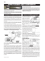
Purge all gas lines with the glass door of the fireplace open.
Assure that a continuous gas flow is at the burner before
closing the door.
Under extreme vent configurations, allow several minutes
(5-15) for the flame to stabilize after ignition.
Eight (8") inches is the minimum bend radius allowed for
the 7" diameter flexible air liner.
Provide adequate ventilation and combustion air. Provide
adequate accessibility clearance for servicing and operat-
ing the fireplace. Never obstruct the front opening of the
fireplace.
Objects placed in front of the fireplace must be kept a
minimum of 48" from the front face of the unit.
Minimum clearance to combustible construction
from fireplace and vent surfaces:
fireplace framing - 0" to stand-offs (top, rear and sides)
fireplace finishing - 3" to sides, 7¼" to top of unit
vent pipe - 2 inches *
recessed depth - 16 inches
* The first 2 feet of outer 7 inch diameter vent pipe from
the appliance must be wrapped in the 1" thick insulation
sleeve (supplied). There must be a 1inch air gap in addi-
tion to the insulation sleeve.
See FSee F
See FSee F
See F
igurigur
igurigur
igur
e 34.e 34.
e 34.e 34.
e 34.
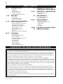
FOR YOUR SATISFACTION, THIS FIREPLACE HAS BEEN
TEST-FIRED TO ASSURE ITS OPERATION AND QUALITY!
Maximum input is 35,000 BTU/hr for natural gas and 33,000
BTU/hr for propane. When the fireplace is installed at eleva-
tions above 4,500ft, and in the absense of specific recom-
mendations from the local authority having jurisdiction, the
certified high altitude input rating shall be reduced at the rate
of 4% for each additional 1,000ft. Maximum output for natural
gas is 28,350 BTU/hr at an efficiency of 81%; and 26,400 BTU/
hr for propane at an efficiency of 80%. Minimum A.F.U.E. rating
is 64% for natural gas and 65% for propane. Minimum inlet
gas supply pressure is 4.5 inches water column for natural
gas and 11 inches water column for propane. Maximum inlet
gas pressure is 7 inches water column for natural gas and 13
inches water column for propane. Manifold pressure under
flow conditions is 3.5 inches water column for natural gas
and 10 inches water column for propane.
This fireplace is approved for bathroom, bedroom and bed-
sitting room installations and is suitable for mobile home
installation. The natural gas model can only be installed in
a mobile home that is permanently positioned on its site
and fueled with natural gas.
WARNING: The door for this fireplace is sold
separately. The door must be installed and
closed before operation begins. Refer to
"DOOR INSTALLATION" under the "FINISH-
ING" Section for details.
FIGURE 1
THIS GAS FIREPLACE SHOULD BE INSTALLED AND
SERVICED BY A QUALIFIED INSTALLER to conform with
local codes. Installation practices vary from region to re-
gion and it is important to know the specifics that apply to
your area,
for example: in Massachusetts State:
• The fireplace damper must be removed or welded in the
open position prior to installation of a fireplace insert or
gas log.
• The appliance off valve must be a “T” handle gas cock.
• The flexible connector must not be longer than 36 inches.
• The appliance is not approved for installation in a
bedroom or bathroom unless the unit is a direct vent
sealed combustion product.
• WARNING: This product must be installed by a licensed
plumber or gas fitter when installed within the
commonwealth of Massachusetts.
In absence of local codes, install to the current CAN/CGA -
B149 Installation Code in Canada or to the National Fuel
Gas Code, ANSI Z223.1, and NFPA 54 in the United States.
Suitable for mobile home installation if installed in accor-
dance with the current standard CAN/CSA Z240MH Series,
for gas equipped mobile homes, in Canada or ANSI Z223.1
and NFPA 54 in the United States.
The fireplace and its individual shutoff valve must be discon-
nected from the gas supply piping system during any pressure
testing of that system at test pressures in excess of 1/2 psig
(3.5 kPa). The fireplace must be isolated from the gas supply
piping system by closing its individual manual shutoff valve
during any pressure testing of the gas supply piping system at
test pressures equal to or less than 1/2 psig (3.5 kPa).
When the fireplace is installed directly on carpeting, vinyl tile or
other combustible material other than wood flooring, the fire-
place shall be installed on a metal or wood panel extending
the full width and depth.
The optional heat circulating blower is supplied with a cord. If
installed, the junction box must be electrically connected and
grounded in accordance with local codes. In the absence of
local codes, use the current CSA C22.1 CANADIAN ELECTRI-
CAL CODE in Canada or the ANSI/NFPA 70 NATIONAL ELEC-
TRICAL CODE in the United States.
GENERAL INSTRUCTIONS
GENERAL INFORMATION

5
W415-0434 / C / 03.24.05
Do not use abrasive cleaners to clean plated parts. Buff
lightly with a clean dry cloth. The glass is 3/16" ceramic
glass available from your Napoleon / Wolf Steel Ltd. dealer.
DO NOT SUBSTITUTE MATERIALS. Clean the glass after
the first 10 hours of operation with a recommended gas
fireplace glass cleaner. Thereafter clean as required. DO
NOT CLEAN GLASS WHEN HOT! If the glass is not kept
clean permanent discolouration and / or blemishes may
result.
This fireplace may This fireplace may
This fireplace may This fireplace may
This fireplace may
be installed in an aftermarket perma-be installed in an aftermarket perma-
be installed in an aftermarket perma-be installed in an aftermarket perma-
be installed in an aftermarket perma-
nently located, manufactured (mobile) home, where notnently located, manufactured (mobile) home, where not
nently located, manufactured (mobile) home, where notnently located, manufactured (mobile) home, where not
nently located, manufactured (mobile) home, where not
prpr
prpr
pr
ohibited bohibited b
ohibited bohibited b
ohibited b
y local codesy local codes
y local codesy local codes
y local codes
..
..
.
This fireplace is only for use with the type of gas indicatedThis fireplace is only for use with the type of gas indicated
This fireplace is only for use with the type of gas indicatedThis fireplace is only for use with the type of gas indicated
This fireplace is only for use with the type of gas indicated
on the ron the r
on the ron the r
on the r
aa
aa
a
ting plating pla
ting plating pla
ting pla
tete
tete
te
. T. T
. T. T
. T
his fhis f
his fhis f
his f
irir
irir
ir
ee
ee
e
place is not conplace is not con
place is not conplace is not con
place is not con
vv
vv
v
erer
erer
er
tibtib
tibtib
tib
le fle f
le fle f
le f
or useor use
or useor use
or use
with other gases, unless a certified kit is used.with other gases, unless a certified kit is used.
with other gases, unless a certified kit is used.with other gases, unless a certified kit is used.
with other gases, unless a certified kit is used.
No external electricity (110 volts or 24 volts) is required forNo external electricity (110 volts or 24 volts) is required for
No external electricity (110 volts or 24 volts) is required forNo external electricity (110 volts or 24 volts) is required for
No external electricity (110 volts or 24 volts) is required for
the gas system operation.the gas system operation.
the gas system operation.the gas system operation.
the gas system operation.
Expansion / contraction noises during heating up and cool-
ing down cycles are normal and are to be expected. Change
in flame appearance from "HI" to "LO" is more evident in
natural gas than in propane.
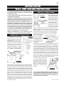
FIGURES 2a-c
Use only Wolf Steel, Simpson Dura-Vent, Selkirk Direct
Temp or American Metal Amerivent venting components.
Minimum and maximum vent lengths, for both horizontal
and vertical installations, and air terminal locations for ei-
ther system are set out in this manual and must be ad-
hered to. For Simpson Dura-Vent,
Selkirk Direct Temp
and American Metal Amerivent, follow the installation
procedure provided with the venting components.
For vent systems that provide seals on the inner exhaust
flue, only the outer air intake joints must be sealed using a
red high temperature silicone (RTV). This same sealant
maybe used on both the inner exhaust and outer intake
vent pipe joints of all other approved vent systems except
for the exhaust vent pipe connection to the fireplace flue
collar which must be sealed using the black high tem-
perature sealant Mill Pac. High temperature sealant must
be ordered separately.
When using Napoleon venting components, use only ap-
proved Wolf Steel Ltd. rigid / flexible vent components with
the following termination kits: WALL TERMINAL KIT GD222,
or 1/12 TO 7/12 PITCH ROOF TERMINAL KIT GD110, 8/12
TO 12/12 ROOF TERMINAL KIT GD111, FLAT ROOF TER-
MINAL KIT GD112 or PERISCOPE KIT GD201 (for wall pen-
etration below grade). With flexible venting, in conjunction
with the various terminations, use either the 5 foot vent kit
GD220 or the 10 foot vent kit GD330. These vent kits allow
for either horizontal or vertical venting of the fireplace. FIG-
URES 2, 3, & 5.
The maximum allowable vertical vent length is 40 feet.
The maximum number of allowable 4" vent connections is
three horizontally or vertically (excluding the fireplace and
the air terminal connections) when using aluminum flex-
ible venting.
For optimum flame appearance and fireplace performance,
keep the vent length and number of elbows to a minimum.
The air terminal must remain unobstructed at all times.
Examine the air terminal at least once a year to verify that it
is unobstructed and undamaged.
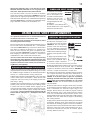
FIGURE 3
CARE OF GLASS, AND PLATED PARTS
When venting, the horizontal run must be kept to a mini-
mum of 12 inches
or a maximum of 20 feet. If a 20 foot
horizontal run is required, the fireplace must have a
minimum vertical rise immediately off the fireplace of
57 inches.
FIGURES FIGURES
FIGURES FIGURES
FIGURES
2a-c2a-c
2a-c2a-c
2a-c
..
..
. When terminating vertically,
the vertical rise is a minimum 34 inches and a maximum
40 feet above the fireplace.
FIGURE 3.FIGURE 3.
FIGURE 3.FIGURE 3.
FIGURE 3.
Horizontal runs may have a 0 inch rise per foot in all
cases using SIMPSON DURA-VENT or NAPOLEON
RIGID OR FLEXIBLE venting components when vent-
ing as illustrated in Figures 2a, 2b, and 2c.
VENTING
VENTING LENGTHS & AIR TERMINAL LOCATIONS
For optimum performance, it is recommended that allFor optimum performance, it is recommended that all
For optimum performance, it is recommended that allFor optimum performance, it is recommended that all
For optimum performance, it is recommended that all
horizontal runs have a minimum ¼ inch rise per foot.horizontal runs have a minimum ¼ inch rise per foot.
horizontal runs have a minimum ¼ inch rise per foot.horizontal runs have a minimum ¼ inch rise per foot.
horizontal runs have a minimum ¼ inch rise per foot.
Wolf Steel rigid and flexible venting systems must not
be combined.
Wolf Steel, Simpson Dura-Vent, Selkirk Direct Temp and
American Metal Amerivent venting systems must not
be combined.
Provide a means for visually checking the vent connec-Provide a means for visually checking the vent connec-
Provide a means for visually checking the vent connec-Provide a means for visually checking the vent connec-
Provide a means for visually checking the vent connec-
tion to the fireplace after the fireplace is installed.tion to the fireplace after the fireplace is installed.
tion to the fireplace after the fireplace is installed.tion to the fireplace after the fireplace is installed.
tion to the fireplace after the fireplace is installed.
Do not allow the inside liner to bunch up on horizontal orDo not allow the inside liner to bunch up on horizontal or
Do not allow the inside liner to bunch up on horizontal orDo not allow the inside liner to bunch up on horizontal or
Do not allow the inside liner to bunch up on horizontal or
vv
vv
v
erer
erer
er
tical rtical r
tical rtical r
tical r
uns and elbowsuns and elbows
uns and elbowsuns and elbows
uns and elbows
. K. K
. K. K
. K
eeee
eeee
ee
p it pulled tight. A p it pulled tight. A
p it pulled tight. A p it pulled tight. A
p it pulled tight. A
1¼"1¼"
1¼"1¼"
1¼"
air air
air air
air
gap between the inner and outer liner all around is re-gap between the inner and outer liner all around is re-
gap between the inner and outer liner all around is re-gap between the inner and outer liner all around is re-
gap between the inner and outer liner all around is re-
quired for safe operation.quired for safe operation.
quired for safe operation.quired for safe operation.
quired for safe operation.
VV
VV
V
ent lengths thaent lengths tha
ent lengths thaent lengths tha
ent lengths tha
t pass thrt pass thr
t pass thrt pass thr
t pass thr
ough unheaough unhea
ough unheaough unhea
ough unhea
ted spaces (ated spaces (a
ted spaces (ated spaces (a
ted spaces (a
t-t-
t-t-
t-
tics, garages, crawl space) should be wrapped with atics, garages, crawl space) should be wrapped with a
tics, garages, crawl space) should be wrapped with atics, garages, crawl space) should be wrapped with a
tics, garages, crawl space) should be wrapped with a
protective insulation sleeve to minimize condensation.protective insulation sleeve to minimize condensation.
protective insulation sleeve to minimize condensation.protective insulation sleeve to minimize condensation.
protective insulation sleeve to minimize condensation.
Use a firestop when penetrating interior walls, floor orUse a firestop when penetrating interior walls, floor or
Use a firestop when penetrating interior walls, floor orUse a firestop when penetrating interior walls, floor or
Use a firestop when penetrating interior walls, floor or
ceiling.ceiling.
ceiling.ceiling.
ceiling.
In order to avoid the possibility of exposed insulation orIn order to avoid the possibility of exposed insulation or
In order to avoid the possibility of exposed insulation orIn order to avoid the possibility of exposed insulation or
In order to avoid the possibility of exposed insulation or
vv
vv
v
aa
aa
a
pour barpour bar
pour barpour bar
pour bar
rier coming in contact with the frier coming in contact with the f
rier coming in contact with the frier coming in contact with the f
rier coming in contact with the f
irir
irir
ir
ee
ee
e
place bodyplace body
place bodyplace body
place body
,,
,,
,
it is recommended that the walls of the fireplace enclo-it is recommended that the walls of the fireplace enclo-
it is recommended that the walls of the fireplace enclo-it is recommended that the walls of the fireplace enclo-
it is recommended that the walls of the fireplace enclo-
sursur
sursur
sur
e be 'fe be 'f
e be 'fe be 'f
e be 'f
inished', (i.einished', (i.e
inished', (i.einished', (i.e
inished', (i.e
. dryw. dryw
. dryw. dryw
. dryw
all/sheetrall/sheetr
all/sheetrall/sheetr
all/sheetr
ococ
ococ
oc
k) as wk) as w
k) as wk) as w
k) as w
ould anyould any
ould anyould any
ould any
other outside wother outside w
other outside wother outside w
other outside w
all ofall of
all ofall of
all of
the home the home
the home the home
the home
. T. T
. T. T
. T
his will ensurhis will ensur
his will ensurhis will ensur
his will ensur
e thae tha
e thae tha
e tha
tt
tt
t
clearance to combustibles is maintained within the cav-clearance to combustibles is maintained within the cav-
clearance to combustibles is maintained within the cav-clearance to combustibles is maintained within the cav-
clearance to combustibles is maintained within the cav-
ityity
ityity
ity
..
..
.
For safe and proper operation of the fireplace followFor safe and proper operation of the fireplace follow
For safe and proper operation of the fireplace followFor safe and proper operation of the fireplace follow
For safe and proper operation of the fireplace follow
the vthe v
the vthe v
the v
enting instrenting instr
enting instrenting instr
enting instr
uction euction e
uction euction e
uction e
xactlyxactly
xactlyxactly
xactly
..
..
.
Deviation from the minimum vertical vent length can cre-Deviation from the minimum vertical vent length can cre-
Deviation from the minimum vertical vent length can cre-Deviation from the minimum vertical vent length can cre-
Deviation from the minimum vertical vent length can cre-
ate difficulty in burner start-up and/or carboning.ate difficulty in burner start-up and/or carboning.
ate difficulty in burner start-up and/or carboning.ate difficulty in burner start-up and/or carboning.
ate difficulty in burner start-up and/or carboning.

6
W415-0434 / C / 03.24.05
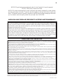
when (H
T
) < (V
T
)
Simple venting configuration (only one 90° elbow)
VERTICAL
RISE IN
FEET
V
T
FIGURE 4
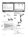
See graph to determine the required vertical rise V
T
for the
required horizontal run H
T
.
For vent configurations requiring more than one 90° el-
bow, the following formulas apply:
Formula 1: H
T
< V
T
Formula 2: H
T
+ V
T
< 40 feet
Example 1:
90°
90°
V
1
=3 ft
V
2
=8 ft
V
T
=
V
1
+
V
2
=
3 + 8 = 11 ft
H
1
= 2.5 ft
H
2
=2 ft
H
R
= H
1
+ H
2
= 2.5 + 2 = 4.5 ft
H
O
=.
03(three 90° elbows - 90°) = .03(270° - 90°) = 5.4 ft
H
T
= H
R
+ H
O
= 4.5 + 5.4 = 9.9 ft
H
T
+ V
T
= 9.9 + 11 = 20.9 ft
Formula 1: H
T
< V
T
9.9 < 11
Formula 2: H
T
+ V
T
< 40 feet
20.9
< 40
Since both formulas are met, this vent configuration is ac-
ceptable.
FIGURE 5
90°
H
1
V
2
H
2
V
1
HORIZONTAL VENT RUN PLUS OFFSET IN FEET
H
T
The shaded area within the lines represents acceptable
values for H
T
and V
T
.
for the following symbols used in the venting calcula-
tions and examples are:
> - greater than
> - equal to or greater than
< - less than
< - equal to or less than
H
T
- total of both horizontal vent lengths (H
R
) and offsets
(H
O
) in feet
H
R
- combined horizontal vent lengths in feet
H
O
- offset factor: .03(total degrees of offset - 90°*) in
feet
V
T
- combined vertical vent lengths in feet
feet inches
1° 0.03 0.5
15° 0.45 6.0
30° 0.9 11.0
45° 1.35 16.0
90°* 2.7 32.0
* the first 90° offset has a zero value and is shown in
the formula as -90°
DEFINITIONS
ELBOW VENT LENGTH VALUES
TOP EXIT / HORIZONTAL TERMINATION

7
W415-0434 / C / 03.24.05
H
2
H
1
V
1
90°
See graph to determine the required ver-
tical rise V
T
for the required horizontal run
H
T
.
V
1
= V
T
= 6 ft
H
1
=3 ft
H
2
=5 ft
H
R
= H
1
+ H
2
= 3 + 5 = 8 ft
H
O
= .03(two 90° elbows - 90°) = .03(180° - 90°) = 2.7 ft
H
T
= H
R
+ H
O
= 8 + 2.7 = 10.7 ft
H
T
+ V
T
=
10.7 + 6 =16.7
Formula 1: H
T
< 4.2 V
T
4.2 V
T
= 4.2 x 6 = 25.2 ft
10.7 < 25.2
Formula 2: H
T
+ V
T
< 24.75 feet
16.7 < 24.75
Since both formulas are met, this vent configuration is ac-
ceptable.
For vent configurations requiring more than one 90° elbow
the following formulas apply:
Formula 1: H
T
< 4.2 V
T
Formula 2: H
T
+ V
T
< 24.75 feet
Example 2:
Example 3:
V
1
=4 ft
V
2
= 1.5 ft
V
T
= V
1
+ V
2
= 4 + 1.5 = 5.5 ft
H
1
=2 ft
H
2
=1 ft
H
3
=1 ft
H
4
= 1.5 ft
H
R
= H
1
+ H
2
+ H
3
+ H
4
= 2 + 1 + 1 + 1. 5 = 5.5 ft
H
O
= .03(four 90° elbows - 90°) = .03(360° - 90°) = 8.1 ft
H
T
= H
R
+ H
O
= 5.5 + 8.1 = 13.6 ft
H
T
+ V
T
= 13.6 + 5.5 = 19.1 ft
Formula 1:H
T
< 4.2 V
T
4.2 V
T
= 4.2 x 5.5 = 23.1 ft
13.6 < 23.1
Formula 2:H
T
+ V
T
< 24.75 feet
19.1 < 24.75
Since both formulas are met, this vent configuration is ac-
ceptable.
FIGURE 6
FIGURE 7
REQUIRED
VERTICAL
RISE IN
INCHES
V
T
HORIZONTAL VENT RUN PLUS OFFSET IN FEET H
T
FIGURE 8
H
2
H
4
V
2
90°
H
3
H
1
V
1
90°
The shaded area within the lines represents acceptable
values for H
T
and V
T
.
when (H
T
) > (V
T
)
Simple venting configuration (only one 90° elbow)
TOP EXIT / HORIZONTAL TERMINATION

8
W415-0434 / C / 03.24.05
REQUIRED
VERTICAL RISE
IN FEET
V
T
HORIZONTAL VENT RUN PLUS OFFSET IN FEET
H
T
The shaded area within the lines represents acceptable
values for H
T
and V
T
.
when (H
T
) < (V
T
)
Simple venting configurations
FIGURE 9
For vent configurations requiring more than zero 90° elbow
(top exit) or one 90° elbow (rear exit), the following formu-
las apply:
Formula 1: H
T
< V
T
Formula 2: H
T
+ V
T
< 40 feet
See graph to determine the required vertical rise V
T
for the
required horizontal run H
T
.
0
5101520
40
10
20
30
3
VERTICAL TERMINATION

9
W415-0434 / C / 03.24.05
0
5101520
10
20
3
25 30
19
MAXIMUM
VERTICAL
RISE IN
FEET
V
T
HORIZONTAL VENT RUN PLUS OFFSET IN FEET
T
The shaded area within the lines represents acceptable
values for H
T
and V
T
.
See graph to determine the required vertical rise V
T
for the
required horizontal run H
T
.
V
1
=2 ft
V
2
=1 ft
V
3
=1.5 ft
V
T
=
V
1
+
V
2
+
V
3
=
2 + 1 + 1.5 = 4.5 ft
H
1
=6 ft
H
2
=2 ft
H
R
= H
1
+ H
2
= 6 + 2 = 8 ft
H
O
= .03(four 90° elbows - 90°)
= .03(90 + 90 + 90 + 90 - 90) = 8.1 ft
H
T
=
H
R
+
H
O
= 8 + 8.1 = 16.1 ft
H
T
+ V
T
= 16.1 + 4.5 = 20.6 ft
Formula 1:
H
T
< 3V
T
3V
T
=
3 x
4.5 = 13.5 ft
16.1 > 13.5
Since this formula is not met, this vent configuration is
unacceptable
.
Formula 2:
H
T
+ V
T
< 40 feet
20.6 < 40
Since only formula 2 is met, this vent configuration is unac-
ceptable and a new fireplace location or vent configuration
will need to be established to satisfy both formulas.
FIGURE 1 0
Formula 1: H
T
< 3V
T
Formula 2: H
T
+ V
T
< 40 feet
Example 7:
FIGURE 11
H
1
H
2
V
3
V
1
90°
90°
90°
V
2
90°
when (H
T
) > (V
T
)
Simple venting configurations
For vent configurations requiring more than two 90°
elbow the following formulas apply:
VERTICAL TERMINATION

10
W415-0434 / C / 03.24.05
AIR TERMINAL INSTALLATIONS
*
*
* Recommended to prevent condensation on windows and thermal breakage
****
****
** It is recommended to use a heat shie
ld and to maximize the distance to vinyl clad soffits.
******
******
*** The periscope GD-201 requires a minimum 18 inche
s clearance fr om an inside corner.
********
********
**** This is a recommended distance. For additional requirements check local codes.
†
†
† Three feet abov e if within 10 feet horizontally.
‡
‡
‡ A vent shall not terminate directly above a sidewalk or paved driveway t hat is located between two single fam
i
dwellings and serves both dwellings.
† †† †
† †† †
† † Permitted only if the veranda, porch, or deck is fully open on a minimum
of two sides beneath the floor.
† *† *
† *† *
† * Recommenced to prevent recirculation of exhaust products. For additional requirements check local codes.
A
B
C
D
E
F
G
H
I
J
K
L
M
N
O
12 INCHES
9 INCHES
12 INCHES*
18 INCHES**
12 INCHES**
0 INCHES
0 INCHES***
2 INCHES***
3 FEET****
3 FEET****
9 INCHES
3 FEET
†
7 FEET****
12 INCHES****
16 INCHES
2 FEET†*
Clearance above grade, veranda porch, deck or balcony.
Clearance to windows or doors that open.
Clearance to permanently closed windows.
Vertical clearance to ventilated soffit located above the terminal within
a horizontal distance of 2 feet from the centerline of the terminal.
Clearance to unventilated soffit.
Clearance to an outside corner wall.
Clearance to an inside non-combustible corner wall or protruding
non-combustible obstructions (chimney, etc.).
Clearance to an inside combustible corner wall or protruding com-
bustible obstructions ( vent chase, etc.).
Clearance to each side of the centerline extended above the meter
/ regulator assembly to a maximum vertical distance of 15ft.
Clearance to a service regulator vent outlet.
Clearance to a non-mechanical air supply inlet to the building or a
combustion air inlet to any other appliance.
Clearance to a mechanical air supply inlet.
Clearance above a paved sidewalk or paved driveway located on
public property unless fitted with a heat shield kit GD-301.
Clearance under a veranda, porch, deck or balcony.
Clearance above the roof.
Clearance from an adjacent wall including neighbouring buildings.
CANADIAN U.S.A.
12 INCHES
12 INCHES
12 INCHES*
18 INCHES**
12 INCHES**
0 INCHES
0 INCHES***
2 INCHES***
3 FEET
3 FEET
12 INCHES
6 FEET
7 FEET‡
12 INCHES††
16 INCHES
2 FEET†*
INSTALLATIONS
FIGURE 12

11
W415-0434 / C / 03.24.05
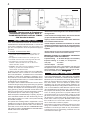
FIGURE 14
OR
This application occurs
when venting through a
roof. Installation kits for
various roof pitches are
available from your Na-
poleon dealer. See Ac-
cessories to order the
specific kit required.
1. Determine the air ter-
minal location, cut and
frame 9½ inch open-
ings in the ceiling and the roof to provide the minimum
clearance between the fireplace pipe / liner and any com-
bustible material. Try to center the exhaust pipe location
midway between two joist to prevent having to cut them.
Use a plumb bob to line up the center of the openings.
DO NOT FILL THIS SPACE WITH ANY TYPE OF MATERIAL.
A vent pipe shield will
prevent any materials
such as insulation,
from filling up the 1"
air space around the
pipe. Nail headers be-
tween the joist for ex-
tra support.
2. Apply a bead of caulking (not supplied) to the framework
or to the Wolf Steel vent pipe shield plate or equivalent (in
the case of a finished ceiling), and secure over the open-
ing in the ceiling. A firestop must be placed on the bottom
of each framed opening in a roof or ceiling that the venting
system passes through. Apply a bead of caulking all around
and place a firestop spacer over the vent shield to restrict
cold air from being drawn into the room or around the fire-
place. Ensure that both spacer and shield maintain the
required clearance to combustibles. Once the vent
pipe / liner is installed in its final position, apply sealant
between the pipe / liner and the firestop spacer.
3. In the attic, after the pipe / liner
has been installed, slide the
vent pipe collar down to cover up
the open end of the shield and
tighten. This will prevent any ma-
terials, such as insulation, from
filling up the 1" air space around
the pipe.
*
The 11½ inch framing dimension may be reduced to a
9½ inch opening if the vent length, from the fireplace to
the framed hole, is 24 inches or greater. If not, it is rec-
ommended to use a terminal extension plate, W500-0103,
when mounting the air terminal.
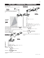
FIGURE 13
*
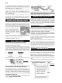
INSTALLATION
WALL AND CEILING PROTECTION
HORIZONTAL INSTALLATION
VERTICAL INSTALLATION
FIGURE 17
FIGURE 16
FIGURE 15
For optimum performance it is recommended that all
horizontal runs have a minimum ¼ inch rise per foot
using flexible venting.
For safe and proper operation of the fireplace, follow the
venting instructions exactly.
HORIZONTAL TERMINATION: A clearance to combus-
tibles of 2" must be maintained during the first 24" of
venting when penetrating combustible walls. The
firestop spacer (GD-500.106 ) supplied with the unit
should be used to maintain this clearance. The first two
feet of outer 7" diameter vent pipe, from the appliance
must be wrapped in the 1 inch thick insulation sleeve
(supplied) as well as having a 1 inch air gap. Thereafter
a 1" clearance to combustibles may be maintained us-
ing firestop spacer (GD-500.96 for use with flexible vent-
ing or GD-500.136 for use with rigid venting).
VERTICAL TERMINATION: Only a clearance to com-
bustibles of 1" all around the vent pipe is required.
HORIZONTAL INSTALLATION:
This application occurs when
venting through an exterior wall.
FIGURES 2a-d. Having deter-
mined the air terminal location,
cut and frame a hole in an exterior
wall with a minimum square or
round opening of 11½"*. (As an
alternative to framing, a vent pipe
shield may be installed, ensuring
a 1" clearance to combustibles.
Mark and cut the vent pipe shield to the determined depth
of the combustible wall. Apply a bead of caulking (not sup-
plied) to the framework or to the shield plate (in the case of
a finished wall) and secure the shield through the opening
to the interior wall. The final location of the vent pipe shield
should maintain the required clearance to the 7" vent
pipe / liner. Do not fill this cavity with any type of material.
Apply a bead of caulking all around and place a firestop
spacer over the vent shield to restrict cold air from being
drawn into the room or around the fireplace. Ensure that
both spacer and shield maintain the required clearance to
combustibles. Once the vent pipe / liner is installed in its
final position, apply sealant between the pipe / liner and
the firestop spacer.

12
W415-0434 / C / 03.24.05
FIGURE 20
Use only approved aluminum flexible liner kits marked
" Wolf Steel Approved Venting" as identified by the
stamp only on the 7" outer liner.
For optimum performance it is recommended that all
horizontal runs have a minimum ¼ inch rise per foot
using flexible venting.
1. Stretch the 4" diameter aluminum flexible liner to the
required length taking into account the additional length
needed for the finished wall surface. Apply a heavy bead of
the high temperature sealant Mill Pac, to the inside of the
4" liner approximately 1" from the end. Slip the liner a mini-
mum of 2" over the fireplace vent collar and secure with 3
#8 screws.
2. Using the 7" diameter flexible aluminum liner, apply seal-
ant, slide a minimum of 2" over the fireplace combustion
air collar and secure with 3 #8 screws.
3. Insert the liners through the firestop. Position and se-
cure the fireplace using the nailing tabs (2 per side) and/or
secure to the floor using screws inserted through the two
¼" diameter holes in the front left and right corners of the
base. The liners should be flush with the exterior wall.
The air terminal may be recessed into the exterior wall
or siding by 1½", the depth of the return flange.
4. From outside, apply a bead of the high temperature seal-
ant to the inside of both liners, approximately 1" from the
end of each liner.
5. Holding the air terminal (lettering in an upright, readable
position), insert into both liners with a twisting motion to
ensure that both the terminal sleeves engage into the lin-
ers / sealant. Secure the terminal to the exterior wall and
make weather tight by sealing with caulking (not supplied).
6. If more liner needs to be used to reach the fireplace,
couple them together as illustrated in FIGURE 13. The vent
system must be supported approximately every 3 feet for
both vertical and horizontal runs. Use Napoleon support
ring assembly W010-0370 or equivalent noncombustible
strapping to maintain the minimum 1" clearance to com-
bustibles.
1. Fasten the roof support to the
roof using the screws pro-
vided. The roof support is
optional. In this case the
venting is to be ad-
equately supported us-
ing either an alternate
method suitable to the
authority having jurisdic-
tion or the optional roof
support.
2. Stretch the 4" diameter alumi-
num flexible liner to the required
length. Slip the liner a minimum
of 2" over the inner sleeve of the
air terminal and secure with 3 #8
screws. Seal using a heavy bead
of the high temperature sealant.
3. Repeat using 7" diameter alu-
minum flexible liner.
4. Thread the air terminal pipe as-
sembly down through the roof.
The air terminal must be located vertically and plumb. At-
tach the air terminal assembly to the roof support, ensur-
ing that a minimum 16" of air terminal will penetrate the
roof when fastened.
DO NOT CLAMP THE
FLEXIBLE ALUMINUM
LINER.
5. Remove nails from
the shingles, above
and to the sides of the
chimney. Place the
flashing over the air ter-
minal and slide it un-
derneath the sides and
upper edge of the shingles. Ensure that the air terminal is
properly centered within the flashing, giving a 3/4" margin
all around. Fasten to the roof. Do not nail through the lower
portion of the flashing. Make weather-tight by sealing with
caulking. Where possible, cover the sides and top edges
of the flashing with roofing material.
6. Apply a heavy bead of weatherproof caulking 2 inches
above the flashing. Slide the storm collar around the air
terminal and down to the caulking. Tighten to ensure that a
weather-tight seal between the air terminal and the collar
is achieved. Attach the other storm collar centered between
the air intake and the air exhaust slots onto the air termi-
nal. Tighten securely. Attach the vertical rain cap.
FIGURE 19
FIGURE 18
USING FLEXIBLE VENT COMPONENTS
HORIZONTAL AIR TERMINAL INSTALLATION
VERTICAL AIR TERMINAL INSTALLATION
FIGURE 21
FIGURE 22
For safe and proper operation of the fireplace, follow the
venting instructions exactly.
All inner exhaust and outer intake vent pipe joists may
be sealed using either Red RTV high temp silicone seal-
ant or Black high temp Mill Pac with the exception of the
fireplace exhaust flue collar which must be sealed us-
ing Mill Pac (not supplied).

13
W415-0434 / C / 03.24.05
FIGURE 23
1. Move the fireplace into position.
2. Fasten the roof support to the
roof using the screws provided.
FIGURE 16. The roof support is
optional. In this case the venting
is to be adequately supported
using either an alternate method
suitable to the authority having ju-
risdiction or the optional roof sup-
port.
3. Apply high temperature seal-
ant to the outer edge of the inner
sleeve of the air terminal. Slip a
4" diameter coupler a minimum
of 2" over the sleeve and secure using 3 screws.
4. Apply high temperature sealant to the outer edge of the of
the outside sleeve of the air terminal. Slip a 7" diameter
coupler over the sleeve and secure as before. FIGURE 19.
Trim the 7" coupler even with the 4" coupler end.
5. Thread the air terminal pipe assembly down through the
roof support and attach, ensuring that a minimum 16" of
air terminal will penetrate the roof when fastened.
FIGURE 18. If the attic space is tight, we recommend
threading the Wolf Steel vent pipe collar or equivalent
loosely onto the air terminal assembly as it is passed
through the attic. The air terminal must be located verti-
cally and plumb.
6. Remove nails from the shingles, above and to the sides
of the chimney. Place the flashing over the air terminal and
slide it underneath the sides and upper edge of the
shingles. Ensure that the air terminal is properly centered
within the flashing, giving a 3/4" margin all around. Fasten
to the roof. Do NOT nail through the lower portion of the
flashing. Make weather-tight by sealing with caulking. Where
possible, cover the sides and top edges of the flashing
with roofing material.
7. Apply a heavy bead of waterproof caulking 2 inches above
the flashing. Slide the storm collar around the air terminal
and down to the caulking. Tighten to ensure that a weather-
tight seal between the air terminal and the collar is achieved.
Attach the other storm collar centered between the air in-
take and air exhaust slots onto the air terminal. Tighten
securely. Attach the rain cap.
FIGURE 24
1. Install the 4 inch diam-
eter aluminum flexible
liner to the fireplace. Se-
cure with 3 screws and flat
washers. Seal the joint
and screw holes using
the high temperature seal-
ant Mill Pac.
2. Install the 7 inch diameter alu-
minum flexible liner to the fireplace.
Attach and seal the joints.
For optimum performance it is recommended that all
horizontal runs have a ¼ inch rise per foot.
For safe and proper operation of the fireplace, follow
the venting instructions exactly.
The vent system must be supported approximately every 3
feet for both vertical and horizontal runs. Use Napoleon
vent spacers W615-0033 every 3 feet and on either side of
each elbow to maintain the minimum 1¼" clearance be-
tween the outer and inner vent pipes. Use Napoleon sup-
port ring assembly W010-0370 or equivalent noncombus-
tible strapping to maintain the minimum 1" clearance to
combustibles for both vertical and horizontal runs.
All inner exhaust and outer intake vent pipe joists may
be sealed using either Red RTV high temp silicone seal-
ant or Black high temp Mill Pac with the exception of the
fireplace exhaust flue collar which must be sealed us-
ing Mill Pac (not supplied).
1. Move the fireplace into position. Measure the vent length
required between terminal and fireplace taking into account
the additional length needed for the finished wall surface
and any 1¼" overlaps between venting components.
2. Apply high temperature sealant Mill Pac to the outer edge
of the 4" inner collar of the fireplace. Attach the first vent
component and secure using 3 self tapping screws. Re-
peat using 7" piping.
3. Holding the air terminal (lettering in an upright, readable
position), insert into both vent pipes with a twisting motion
to ensure that both the terminal sleeves engage into the
vent pipes and the sealant. Secure the terminal to the exte-
rior wall and make weather tight by sealing with caulking
(not supplied). The air terminal may be recessed into the
exterior wall or siding by 1½", the depth of the return
flange.
FIREPLACE VENT CONNECTION
USING RIGID VENT COMPONENTS
HORIZONTAL AIR TERMINAL INSTALLATION
VERTICAL VENTING INSTALLATION
FIGURE 25
Spacers are attached to the 4" inner flex liner at prede-
termined intervals to maintain a 1-1/4" air gap to the 7"
outer liner. These spacers must not be removed.
7. If more liner needs to be used to reach the fireplace,
couple them together as illustrated in FIGURE 13. The vent
system must be supported approximately every 3 feet for
both vertical and horizontal runs. Use Wolf Steel support ring
assembly W010-0370 or equivalent noncombustible strap-
ping to maintain a clearance to combustibles of 1".

14
W415-0434 / C / 03.24.05
* *
* *
* When using the optional ornamental facia and panels,
the minimum height from the top of the unit to the mantle
is 7".
** A steel stud header is recommended, however tradi-
tional combustible header material may be used.
TILES
GD425
BLACK PAINTED FIREPLACE
SURFACE
Tiles must not pro-
trude past the inner
edge of the fireplace
frame to avoid inter-
ference with the
GD425 installation.
Note: In order to avoid the possibility of exposed
insulation or vapour barrier coming in contact with the
fireplace body, it is recommended that the walls of the
fireplace enclosure be “finished” (ie: drywall/
sheetrock), as you would finish any other outside wall
of a home. This will ensure theat clearance to combus-
tibles is maintained within the cavity.
It is not necessary to install a hearth extension, but the
fireplace should be raised up to be flush with either the
hearth or the finished floor.
When roughing in the fireplace, raise the fireplace to ac-
commodate for the thickness of the finished floor materi-
als, i.e. tile, carpeting, hard wood, which if not planned for
will interfere with the opening of the lower access door and
the installation of many decorative flashing accessories.
Objects placed in front of the fireplace should be kept a
minimum of 48" away from the front face.
8. Continue adding rigid venting sections, sealing and
securing as above. Attach a 4" collapsed telescopic pipe to
the last section of rigid piping. Secure with screws and
seal. Repeat using a 7" telescopic pipe.
9. Run a bead of high temperature sealant around the
outside of the 4" elbow. Pull the adjustable pipe a mini-
mum 2" onto the elbow. Secure with 3 screws. Repeat with
the 7" telescopic pipe.
10. In the attic, slide the vent pipe collar down to cover up
the open end of the shield and tighten. This will prevent
any materials, such as insulation, from filling up the 1" air
space around the pipe.
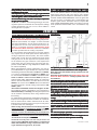
Vertical terminations may display a very active flame. If this
appearance is not desirable, the vent exit must be restricted
using restrictor supplied. This reduces the velocity of the
exhaust gases, slowing down the flame pattern and creat-
ing a more traditional appearance.
1. Remove all obstructing obsta-
cles i.e.: brick panels, logs, etc.
2. Remove the baffle plate from the
rear wall of the firebox, exposing
the two screws from the flue pipe
assembly.
3. Line up the "A" holes on the restrictor plate with the pipe
assembly holes and replace the screws.
4. Replace brick panels, logs, etc.
Purge all gas lines with the glass door of the fire-
place open. Assure that a continuous gas flow is
at the burner before closing the door.
The fireplace is equipped with two 1/4" diameter holes
located in the front left and right corners of the base. For
mobile home installations, the fireplace must be fastened
in place. Use #10 screws, inserted through the holes in
the base to secure. It is recommended that the fireplace
be secured in all installations.
FIGURE 27
FIGURE 26
GAS INSTALLATION
MOBILE HOME INSTALLATION
FRAMING
RESTRICTING VERTICAL VENTS
Non-combustible material (brick, stone or ceramic tile) may
protrude over the black painted surface of the fireplace
front and is required for use in conjunction with the GD425
kit. This kit is designed to accommodate a noncombus-
tible material to a maximum finished thickness of
3
/
4
".
PROTRUDING FINISH
Proceed once the vent installation is complete.
1. Route a 3/8" N.P.T. black iron gas line, 1/2" type-L copper
tubing or equivalent to the fireplace.
2. For ease of accessibility, an optional remote wall switch
or millivolt thermostat may be installed in a convenient
location. Route 2 strand (solid core) millivolt wire through
the electrical hole located at the bottom left side of the unit.
The recommended maximum lead length depends on wire
size: WIRE SIZE MAX. LENGTH
14 gauge 100 feet
16 gauge 60 feet
18 gauge 40 feet
Attach the two leads to terminals 1 and 3 located on the
gas valve.
Do not connect either the wall switch, thermo-
stat or gas valve to electricity (110 volts).
3. Install rigid black pipe, 1/2" type-L copper tubing or, if
local codes permit, a 3/8" flex connector and shutoff valve
to the gas line and the fireplace gas valve. Seal and tighten
securely. An adaptor fitting is required between the gas
valve and the copper tubing or flex connector. DO NOT KINK
THE FLEXIBLE CONNECTOR.
4. Check for gas leaks by brushing on a soap and water
solution. DO NOT USE OPEN FLAME.
FIGURE 33
HOLE "A"

15
W415-0434 / C / 03.24.05
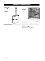
Combustible mantle clearance can vary according to the
mantle depth. Use the graph to help evaluate the clear-
ance needed.
FIGURE 37
MANTLE CLEARANCES
**
EXAMPLE A - NON-COMBUSTIBLE MATERIAL
It is best to frame your fireplace after it is positioned and
the vent system is installed. Use 2x4's and frame to local
building codes. To install the fireplace face flush with the
finished wall, position the framework to accomodate the
thickness of the finished wall.
MAINTAIN THESE MINIMUM CLEARANCES TO COM-
BUSTIBLES:
Fireplace framing - 0" to stand-offs (top, rear & sides)
Fireplace finishing - 3" to sides, 7¼" to top of unit
FIGURE 29
FIGURE 30
EXAMPLE B - BEVELLED TRIM
The non-combustible finishing material may be eliminated
if the intent is to finish the unit with the optional 6" bevelled
trim.
FIGURE 28
FIGURE 36
FIGURE 35
FIGURE 34
FLUSH FINISH
To install the fireplace face flush with the finished wall,
position the framework to accomodate the thickness of the
finished wall.
FIGURE 31
FIGURE 32

16
W415-0434 / C / 03.24.05
Open the valve control door.
Hook the top and bottom door
latches, located at the right
side of the door into the corre-
sponding slots in the door.
The door latch holes are elongated for door levelling. To
level the door, it may need to be lifte
d up at the right
side before latching to ensure the door is level.
Prior to opening the door, lift up and remove the upper lou-
vres or ornamental insets.
HINGE SCREEN
Remove the hinge screen, if factory installed.
Screw the lower louvre assembly to the lip of the fireplace
base as shown. Position the hinge screen into place and
with the control door open, secure to the firebox using three
screws.
Remove the pro-
tective plastic wrap
from the louvres
and install as illus-
trated.
Clip each upper
louvre into a slot on
the louvre bracket.
Ensure that the
louvres are cen-
tered within the
opening.
FIGURE 42: LOWER LOUVRE ASSEMBLY
LOUVRE
BRACKET
FIGURE 40
UPPER LOUVRE INSTALLATION
FIGURE 41
FIGURE 39
DOOR CLOSING AND OPENING
GDLV LOUVRE INSTALLATION
Loosely thread a screw provided with the door kit into the
top hole on the left side of the firebox. Hang the door by the
hinge onto the screw. Insert the remaining 4 screws and
tighten.
IMPORTANT:
Ensure screws are driven in straight or the
hole thread may be damaged.
FINISHING
DOOR INSTALLATION
FIGURE 38
HINGE
SCREEN

17
W415-0434 / C / 03.24.05
A
C
B
L38 LOUVRE INSTALLATION
FIGURE 43 a-c
HOOD
Attach the hood by pressing the
top flange into the clips along
the top of the louvre opening.
Secure using a screw through
the centre slot.
LOWER LOUVRES
Insert the hinge clips into the
slots located at the bottom left
and right corners of the unit.
To remove the louvres, pull the
back tabs of the clips forward,
while pushing the louvre assem-
bly back. Lift the clip.
UPPER LOUVRES
Insert the louvre tabs into the
slots located at the top left and
right corners of the unit.
A
CLIPS
CENTRE
SLOT
FLANGE
SLOT
TAB
B
C
HINGE
CLIP
SLOT
Before installing the logs, you must first remove the log
shipping bracket. Loosen the securing screw indicated.
Slide the bracket to the right and lift up to remove.
LOG SHIPPING BRACKET
LOG SHIPPING
BRACKET
SCREW
FIGURE 45
DECORATIVE PANELS
This fireplace does not include decorative brick panels,
however, panels are required.
You now have the option of choosing 1 of 4 panel kits SOLD
SEPARATELY. (See Accessories).
CHARCOAL STRIPS
The charcoal strips have been shipped in place.
Protective foam must be removed before operation.

18
W415-0434 / C / 03.24.05
Glowing embers (not supplied) maybe used to enhance
the flame's appearance.
4. Place log #4, with the charred branch pointed inward.
Locate the pins into the holes in log#1 and log#2, this will
hold the rear log in position.
5. Place the end of log #5 on the right end of log #1. The
fork in the log should straddle the knot on top of log #2.
GLOWING EMBERS
BAFFLE INSTALLATION
CHARCOAL EMBERS
PHAZER
TM
logs, exclusive to Napoleon Fireplaces, pro-
vide a unique and realistic glowing effect that is different in
every installation.
1. Centre the two charcoal strips, as shown, along the
inside front edge of the firebox.
Place the rear log #1 onto the locating studs along the
back edge of the PHAZERAMIC™ burner.
2. Position log #2 onto the locators on the PHAZERAMIC™
burner.
3. Position log #3 onto the right most grate rail with the
charred face to the front. Align the groove on the underside
of the log, with the rail of the grate. Push the log back to the
pilot housing. Log #3 should fit tight against log #2.
LOG PLACEMENT
2
3
4
FIGURES 46a-e
1
CHARCOAL STRIPS
5
Your fireplace has been supplied with the decorative brick
panels installed. It will be necessary, however, to install the
fibre baffle, on top of the side and rear panels.
Charcoal provided should be randomly placed in the trian-
gular trays on either side of the of the burner.
Log colourLog colour
Log colourLog colour
Log colour
ss
ss
s
mama
mama
ma
y vy v
y vy v
y v
aryary
aryary
ary
. During the initial use of. During the initial use of
. During the initial use of. During the initial use of
. During the initial use of
the f the f
the f the f
the f
irir
irir
ir
e-e-
e-e-
e-
place, the colours will become more uniform as colourplace, the colours will become more uniform as colour
place, the colours will become more uniform as colourplace, the colours will become more uniform as colour
place, the colours will become more uniform as colour
pigments burn in during the heat activated curing pro-pigments burn in during the heat activated curing pro-
pigments burn in during the heat activated curing pro-pigments burn in during the heat activated curing pro-
pigments burn in during the heat activated curing pro-
cesscess
cesscess
cess
..
..
.
Positioning the logs improperly will cause flame im-
pingement and carboning.
Blocked burner ports can cause an incorrect flame pattern,
carbon deposits and delayed ignition. PHAZER
TM
logs glow
when exposed to direct flame. Use only certified PHAZER
TM
logs available from your Napoleon dealer.

19
W415-0434 / C / 03.24.05
The FIRE LOG ACCENT LIGHT is provided with a manual "in-
line" switch to turn the light on and off. There are alternate meth-
ods of operating the light.
An example of one method would be to "hard-wire" a wall switch.
The switch could be installed in desired location to operate the
FIRE LOG ACCENT LIGHT plugged into one of the two recepta-
cles on the fireplace junction box. The other receptacle would still
have power to operate other accessories (see schematic be-
low).
This switch could be:
• Toggle
• Photo cell
• Remote
• Motion Sensor
All switches are available at your building store.
NOTE
ELECTRICAL INSTELECTRICAL INST
ELECTRICAL INSTELECTRICAL INST
ELECTRICAL INST
ALLALL
ALLALL
ALL
AA
AA
A
TION TTION T
TION TTION T
TION T
O BE DONE BY AO BE DONE BY A
O BE DONE BY AO BE DONE BY A
O BE DONE BY A
QUQU
QUQU
QU
ALIFIED INSTALIFIED INST
ALIFIED INSTALIFIED INST
ALIFIED INST
ALLER ALLER
ALLER ALLER
ALLER
and mand m
and mand m
and m
ust be connected andust be connected and
ust be connected andust be connected and
ust be connected and
gg
gg
g
rr
rr
r
ounded in accorounded in accor
ounded in accorounded in accor
ounded in accor
dance with local codesdance with local codes
dance with local codesdance with local codes
dance with local codes
..
..
.
Your Napoleon STARfire comes equipped with our “Accent
Lite”. The light has been pre-wired and can be controlled
from the switch on the control panel.
It is recommended that the ACCENT LITE be in the off
position when the fireplace is on.
If in the event the lamp
or lens needs to be
replaced, follow the
instructions below.
Unplug the light from
inside the fireplace.
Remove the four screws that secure the lens frame.
This frame
retains the
glass lens.
The lamp can
now be
accessed.
Note:Note:
Note:Note:
Note:
Do not handle the lamp (bulb) with bare fingers, Do not handle the lamp (bulb) with bare fingers,
Do not handle the lamp (bulb) with bare fingers, Do not handle the lamp (bulb) with bare fingers,
Do not handle the lamp (bulb) with bare fingers,
protect with a clean dry cloth.protect with a clean dry cloth.
protect with a clean dry cloth.protect with a clean dry cloth.
protect with a clean dry cloth.
The lamp will pull straight out of the socket. Replace with
Wolf Steel parts only, as lamp and lens are special “high
temperature” products.
When re-installing, ensure integrity of gasket seal.
THE FIREBOX MUST BE SEALED.
OvOv
OvOv
Ov
er tightening the screr tightening the scr
er tightening the screr tightening the scr
er tightening the scr
ee
ee
e
ws could brws could br
ws could brws could br
ws could br
eak the lenseak the lens
eak the lenseak the lens
eak the lens
..
..
.
“Light Leakage” from the upper louvre area may be“Light Leakage” from the upper louvre area may be
“Light Leakage” from the upper louvre area may be“Light Leakage” from the upper louvre area may be
“Light Leakage” from the upper louvre area may be
noticed. The holes in the lamp housing are necessarynoticed. The holes in the lamp housing are necessary
noticed. The holes in the lamp housing are necessarynoticed. The holes in the lamp housing are necessary
noticed. The holes in the lamp housing are necessary
for ventilation and must not be covered.for ventilation and must not be covered.
for ventilation and must not be covered.for ventilation and must not be covered.
for ventilation and must not be covered.
ACCENT LITE REPLACEMENT
FIGURE 47
FIGURE 49
IN LINE SWITCH
FIGURE 50a
FIGURE 50b
LENSE
ASSEMBLY
FIREBOX TOP
LENSE
ASSEMBLY
FIREBOX TOP
SCREWS
SCREWS
FIGURE 48

20
W415-0434 / C / 03.24.05
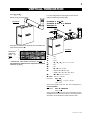
BLOWER INSTALLATION
FIGURE 51
The Napoleon STARfire comes equipped with a blower, a
heat sensor, variable on/off speed control and a power cord.
The blower is thermally activated, so when it is turned on, it
will automatically start approximately 15 minutes after light-
ing the fireplace and will run for approximately 30 minutes
after the fireplace has been turned off. Use of the fan in-
creases the output of heat. Air, drawn in through the lower
louvre access door, is driven up the back of the firebox, and
exhausted as hot air between the upper louvres.
BLOWER SYSTEM
1. Open the lower control area.
2. Remove the control panel (3 screws).
3. Unplug the blower from the junction box or turn off the
power to the fireplace if hardwired.
4. Undo the fastener at the left side of the blower mounting
plate. The blower should now slide to the left, away from
the mounting tab.
5. Finally, disconnect the slip-on connectors at the motor of
the blower.
The wire harness provided in this kit is a universal har-The wire harness provided in this kit is a universal har-
The wire harness provided in this kit is a universal har-The wire harness provided in this kit is a universal har-
The wire harness provided in this kit is a universal har-
nessness
nessness
ness
. When installed, ensur. When installed, ensur
. When installed, ensur. When installed, ensur
. When installed, ensur
e thae tha
e thae tha
e tha
t any et any e
t any et any e
t any e
xx
xx
x
cess wircess wir
cess wircess wir
cess wir
e ise is
e ise is
e is
contained, preventing it from making contact with anycontained, preventing it from making contact with any
contained, preventing it from making contact with anycontained, preventing it from making contact with any
contained, preventing it from making contact with any
momo
momo
mo
ving or hot objectsving or hot objects
ving or hot objectsving or hot objects
ving or hot objects
..
..
.
Drywall dust will penetrate into the blower bearings,Drywall dust will penetrate into the blower bearings,
Drywall dust will penetrate into the blower bearings,Drywall dust will penetrate into the blower bearings,
Drywall dust will penetrate into the blower bearings,
causing ircausing ir
causing ircausing ir
causing ir
rr
rr
r
ee
ee
e
parpar
parpar
par
aa
a
a
a
bb
bb
b
le damale dama
le damale dama
le dama
gg
gg
g
ee
ee
e
. Car. Car
. Car. Car
. Car
e me m
e me m
e m
ust be takust be tak
ust be takust be tak
ust be tak
en toen to
en toen to
en to
prevent drywall dust from coming into contact with theprevent drywall dust from coming into contact with the
prevent drywall dust from coming into contact with theprevent drywall dust from coming into contact with the
prevent drywall dust from coming into contact with the
blower or its compartment. Any damage resulting fromblower or its compartment. Any damage resulting from
blower or its compartment. Any damage resulting fromblower or its compartment. Any damage resulting from
blower or its compartment. Any damage resulting from
this condition is not cothis condition is not co
this condition is not cothis condition is not co
this condition is not co
vv
vv
v
erer
erer
er
ed bed b
ed bed b
ed b
y the wy the w
y the wy the w
y the w
arar
arar
ar
rr
rr
r
anty policanty polic
anty policanty polic
anty polic
yy
yy
y
..
..
.
THERMODISC REPLACEMENT
The thermodisc is located to the left side of the lower con-
trol area, on a bracket and mounted beside the junction
box.
1. Unplug the blower from the junction box or turn off the
power to the fireplace if hardwired.
2. Remove the fastener. Pivot the bracket out from the fire-
box side.
3. Disconnect the slip-on connectors and remove the
thermodisc from the bracket.
FIGURE 54
BLOWER REPLACEMENT
B
A
FIGURE 52
C
FIGURE 53
Page is loading ...
Page is loading ...
Page is loading ...
Page is loading ...
Page is loading ...
Page is loading ...
Page is loading ...
Page is loading ...
-
 1
1
-
 2
2
-
 3
3
-
 4
4
-
 5
5
-
 6
6
-
 7
7
-
 8
8
-
 9
9
-
 10
10
-
 11
11
-
 12
12
-
 13
13
-
 14
14
-
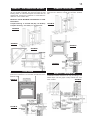 15
15
-
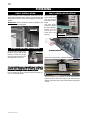 16
16
-
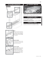 17
17
-
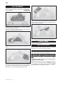 18
18
-
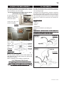 19
19
-
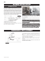 20
20
-
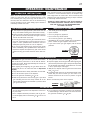 21
21
-
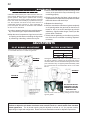 22
22
-
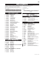 23
23
-
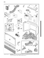 24
24
-
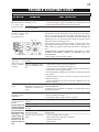 25
25
-
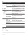 26
26
-
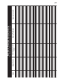 27
27
-
 28
28


Napoleon Fireplaces GD70PT-S User manual
- Category
- Fireplaces
- Type
- User manual
- This manual is also suitable for
Ask a question and I''ll find the answer in the document
Finding information in a document is now easier with AI
Related papers
-
Napoleon Fireplaces B36DFP User manual
-
-
-
-
-
-
-
-
-
Other documents
-
NAPOLEON StarFire GD70PT-S Installation And Operation Instructions Manual
-
 Active Ventilation KV-8-GR Specification
-
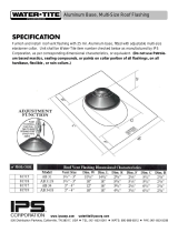 Water-Tite 81715 Operating instructions
-
-
Everbilt BPGH4WHD6 Operating instructions
-
-
-

