
Use and Care of Recirculation Hood Model JN327
and Ventilating Hood Models JV327, JV337 & JV347
IMPORTANT SAFETY
INFORMATION
READ ALL INSTRUCTIONS
BEFORE USING.
WARNING—TO REDUCE THE RISK
OF FIRE, ELECTRIC SHOCK OR
INJURY TO PERSONS, OBSERVE
THE FOLLOWING:
A. Use this unit only in the manner intended by
the manufacturer. If you have any questions,
contact the manufacturer.
B. Before servicing or cleaning unit, switch
power off at service panel and lock the service
disconnecting means to prevent power from
being switched on accidentally. When the service
disconnecting means cannot be locked, securely
fasten a prominent warning device, such as a tag,
to the service panel.
CAUTION—For general ventilating use only.
Do not use to exhaust hazardous or explosive
materials and vapors.
When you get your new hood…
• Have it installed and properly grounded by
a qualified technician in accordance with the
installation instructions.
• Have the installer show you the location of
the hood circuit breaker or fuse and mark it
for easy reference.
• Take the time to read our suggestions for best use.
WARNING—TO REDUCE THE RISK
OF FIRE, ELECTRIC SHOCK OR
INJURY TO PERSONS, OBSERVE
THE FOLLOWING:
A. Installation work and electrical wiring must be
done by qualified person(s) in accordance with
all applicable codes and standards, including
fire-rated construction.
B. Sufficient air is needed for proper combustion
and exhausting of gases through the flue
(chimney) of fuel burning equipment to prevent
back drafting. Follow the heating equipment
manufacturer’s guidelines and safety standards
such as those published by the National Fire
Protection Association (NFPA), and the
American Society for Heating, Refrigeration
and Air Conditioning Engineers (ASHRAE),
and the local code authorities.
C. When cutting or drilling into wall or ceiling,
do not damage electrical wiring and other
hidden utilities.
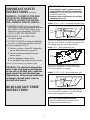
D. Ducted fans must always be vented to the
outdoors.
WARNING—To reduce the risk of fire,
use only metal ductwork.
When using your hood…
• Never leave surface units unattended at high
settings. Boilover causes smoking and greasy
spillovers that may ignite and spread if hood is
used. Use surface unit heat settings recommended
by the manufacturer and adequate-size utensils.
• Never use your cooking appliance for warming
or heating the room. The electrical wiring of
your range hood may not withstand the resulting
excessive heat.
• Keep the hood clean and clean grease filter
or replace charcoal filter as recommended to
maintain good venting and to avoid grease fires.
WARNING—TO REDUCE THE RISK
OFA RANGE TOP GREASE FIRE:
A. Never leave surface units unattended at high
settings. Boilovers cause smoking and greasy
spillovers that may ignite. Heat oils slowly on
low or medium settings.
B. Always turn hood ON when cooking at high
heat or when cooking flaming foods.
C. Clean ventilating fans frequently. Grease should
not be allowed to accumulate on fan or filter.
D. Use proper pan size. Always use cookware
appropriate for the size of the surface element.
(continued next page)
GE Quality Product

IMPORTANT SAFETY
INSTRUCTIONS (continued)
WARNING—TO REDUCE THE RISK
OF INJURY TO PERSONS IN THE
EVENT OFA RANGE TOP GREASE
FIRE, OBSERVE THE FOLLOWING:
*
A. SMOTHER FLAMES with a close-fitting lid,
cookie sheet, or metal tray, then turn off the burner.
BE CAREFUL TO PREVENT BURNS. If the
flames do not go out immediately, EVACUATE
AND CALL THE FIRE DEPARTMENT.
B. NEVER PICK UPA FLAMING PAN—
You may be burned.
C. DO NOT USE WATER, including wet dishcloths
or towels—a violent steam explosion will result.
D. Use an extinguisher ONLY if:
1. You know you have a Class ABC extinguisher,
and you already know how to operate it.
2. The fire is small and contained in the area
where it started.
3. The fire department is being called.
4. You can fight the fire with your back to an exit.
*Based on “Kitchen Firesafety Tips” published by NFPA.
WARNING: The electrical wiring and fan
motor in this range hood are not intended
for use with, or provided with, a solid state
speed control. Any such alteration from
original factory wiring concept could result
in damage to the unit and/or create an
electrical safety hazard.
READ AND SAVE THESE
INSTRUCTIONS
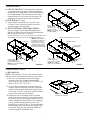
Models: JN327 & JV347—non-ducted installations only
Your hood is equipped with a replaceable charcoal filter.
When the fan is operated, air is drawn through the filter
and discharged into the room through the hood.
Model: JV327—ducted installations only
Your hood is equipped with a metal grease filter.
When the fan is operated, air is drawn through the
filter and discharged to the outside.
Models: JV337 & JV347—ducted installations only
Your hood is equipped with a reusable metal grease
filter. When the fan is operated, air is drawn through
the filter and discharged to the outside.
CAUTION—before operating the hood:
• Install the lamp bulb (not provided). See the
Lamp Replacement instructions.
If You Need Service…
• Do not attempt to repair or replace any part of
your hood unless it is specifically recommended
in this book. All other servicing should be referred
to a qualified technician.
• Disconnect hood circuit breaker or fuse before
performing any service.
2
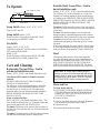
Replaceable charcoal filter
Grease
filter
(Model JV347 has a lamp cover.)
Lamp
holder
Grease filter
(Model JV347 has a lamp cover.)
Lamp
holder
Lamp
holder

To Operate
Lamp Switch
Models: JN327, JV327, JV337
Press for OFF and ON.
Lamp Switch
Model: JV347
Rotate clockwise, first position for NIGHT LIGHT,
second position for BRIGHT LIGHT.
Fan Switch
Models: JN327, JV327, JV337
CENTER position OFF, DOWN position LOW SPEED,
TOP position HIGH SPEED.
Model: JV347
Rotate Clockwise, FIRST position HIGH, SECOND
position MEDIUM, THIRD position LOW.
Care and Cleaning
Replaceable Charcoal Filter—Used in
non-ducted installations only.
Models: JN327, JV347—non-ducted installations only
The charcoal filter cannot be cleaned. It must be
replaced.
DO NOT RINSE OR PLACE THE CHARCOAL
FILTER IN A DISHWASHER.
The efficiency of your hood depends upon a clean filter.
The frequency of filter replacement depends on hood
use and the type of cooking you do. See replacement
guidelines below for your non-ducted model installation.
NEVER OPERATE THE HOOD WITHOUT THE
FILTER IN PLACE.
When to replace the filter:
JN327 and JV347 (non-ducted installations only)—The
filter should be replaced after 6 to 12 months. Order and
replace with genuine GE part: WB02X10700.
To remove: Pull down on the center of the front edge of
the filter. The filter will then slip out of the retaining tabs
on the back.
To replace:
Slip the back edge of the filter into the retaining
tabs and push the front edge up until it snaps in place.
Reusable Metal Grease Filter—Used in
ducted installations only.
Models: JV327, JV337, JV347—ducted installations only
The efficiency of your hood depends on a clean filter.
Frequency of cleaning depends on hood use and the type
of cooking you do. HOWEVER, THE GREASE FILTER
SHOULD BE CLEANED AT LEAST ONCE A MONTH.
NEVER OPERATE THE HOOD WITHOUT THE
FILTER IN PLACE.
To remove: Pull down on the center of the front edge of
the filter. The filter will then slip out of the retaining tabs
on the back.
To clean: Soak and then agitate it in a hot water and
detergent solution. Light brushing can be used to remove
embedded dirt. Rinse, shake and let it dry before replacing.
To replace: Slip the back edge of the filter into the
retaining tabs and push the front edge up until it snaps
into place.
With careful handling, the metal filter will last for years.
If a new replacement becomes necessary, order the part
from your dealer. Order genuine GE part: WB02X8391.
Hood
Clean grease laden surfaces of the hood frequently.
Use warm detergent solution. About 1 tablespoon of
ammonia may be added to the water. TAKE CARE TO
NOT COME IN CONTACT WITH FILTERS AND
OTHER NON-ENAMELED SURFACES. The hood
shell can be washed, rinsed and dried with a soft cloth.
Motor and Fan
To Clean Motor and Fan
1. DISCONNECT THE HOOD POWER SUPPLY AT
THE HOUSEHOLD DISTRIBUTION PANEL BY
REMOVING THE FUSE OR SWITCHING OFF
THE CIRCUIT BREAKER.
2. Remove the filter.
3. Wipe the fan blade and motor with cloth, dampened
only in ammonia and warm water solution.
4. Replace the filter.
5. Reconnect the hood power supply.
CAUTION: Be certain when cleaning the hood
surfaces you do not touch the lamp bulb with moist
hands or cloth. A warm or hot lamp bulb may break
if touched with a moist surface. ALWAYS let lamp
cool COMPLETELY before cleaning around it.
3
Vents (JN327 & JV347)
Fan switch Lamp switch

WARNING—TO REDUCE THE RISK OF
FIRE, ELECTRIC SHOCK, OR INJURY TO
PERSONS, OBSERVE THE FOLLOWING:
A. Installation work and electrical wiring
must be done by qualified persons(s) in
accordance with all applicable codes and
standards, including fire-rated construction.
B. When cutting or drilling into wall or ceiling,
do not damage electrical wiring and other
hidden utilities.
C. Ducted fans must always be vented to the
outdoors.
WARNING—To reduce the risk of fire,
use only metal ductwork.
Important—Save for the local electrical
inspector’s use.
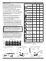
JN327
JV327
JV337
JV347
Installation Instructions for
General Electric Hood
Power supply connection box
on underside of hood.
Exhaust Outlet
12″
12″
5
1
⁄
2
″
5
1
⁄
2
″
12″
17
1
⁄
2
″
17
1
⁄
2
″
5
1
⁄
2
″
17
1
⁄
2
″
30″
Power supply connection box
on underside of hood.
Exhaust Outlet
30″
Exhaust Outlet Knockouts
4
Power supply connection box
on underside of hood.
30″
5
1
⁄
2
″
12″
17
1
⁄
2
″
Exhaust Outlet
Knockouts
Power supply
connection box on
underside of hood.
30″
For ducted installations,
remove the baffle and re-install
so the short side marked
“VENTED” is visible. The long
side of the baffle should be
inside the hood.

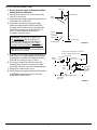
1. PREPARATION OF WALL CABINET
AND WALL
NOTE: For easier installation make all hood and
vent cutouts in the cabinet and wall before cabinet is
permanently fastened in place. It is recommended that
the power supply be brought into the hood from the
wall below the cabinet as shown in Fig.1. However,
an optional location is shown in Fig. 2, where the power
supply enters the top of the hood by passing through
the wall cabinet.
A. WALL CABINET WITH RECESSED BOTTOM:
Add the 2 required filler strips as shown in Fig. 3.
B. WALL CABINET WITH FLUSH BOTTOM: In some
cases it may be necessary to provide clearance for the
connection box cover mounting screw which extends
slightly through the top of the hood. Clearance can be
provided, if necessary, by carefully positioning the
hood against the bottom of the cabinet and marking the
screw position; clearance may then be provided by
drilling a 1/4″ hole in the cabinet bottom.
NOTE: Hood Model JV347 is shipped set up in the
non-ducted configuration.
2. DUCT INSTALLATION
Model JV327 See Figs. 4 & 9
The hood has been designed to mate with a standard 7″
round duct. (A round damper kit may be ordered. Order
GE model number JXDA22.)*
A. If a rectangular duct is desired, a round to rectangular
adapter must be used. Install a 4″ minimum length of
7″ round duct between the hood and adapter to obtain
proper operation of the outlet damper.
B. If a 6″ round duct is desired, a 7″ to 6″ reducer is
required. Install a 4″ minimum length of 7″ round
duct between the hood and adapter to obtain proper
operation of the outlet damper.
CAUTION: Do not fasten the duct to the flange on the
top of the hood with screws. The screws will interfere
with the fan blade, damaging the motor.
5
RECESSED BOTTOM
FIGURE 3
Filler
strip
2
1
⁄2″ min.
These filler strips
support the entire
weight of the hood.
Make sure they are
mounted firmly and
are flush with the
cabinet bottom.
FLUSH OR RECESSED BOTTOM CABINET
FIGURE 1
1
1
⁄2″ dia. clearance hole in wall for
recommended power supply location
Centerline matches up with
center of range or cooktop.
1
1
⁄2″ dia.
clearance holes
for optional power
supply location
FIGURE 2
66″ from bottom
of cabinet to floor
1
1
⁄4″
7
3
⁄4″
1
1
⁄4″
Cabinet
Ceiling
1
1
⁄4″
7
3
⁄4″
Center line
Soffit
(optional)

Models JV337, JV347
Model JV347 ducted installation: Use the reusable
metal grease filter (WB02X8391). Remove the baffle
from the top of the hood. Re-install the baffle so the
short side marked “VENTED” is visible. The long side
of the baffle should be inside the hood.
The hood has been designed to mate with a standard
3
1
⁄4″ x 10″ rectangular or 7″ diameter round duct.
Rectangular Duct See Figs. 5, 6 & 10: The exhaust outlet
can be installed as either the top or rear by removing the
desired rectangular knockout. A rectangular damper is
supplied with the hood.
Round Duct See Figs. 4 & 9: If round duct is desired,
either of the following methods must be used:
1. Install a 4″ minimum length of rectangular duct
between the hood and adapter to obtain proper
operating of the outlet damper, or
2. Remove the round knockout on the top of the hood.
Drill an appropriate size hole in each of the three tabs.
Using pliers, bend the three tabs perpendicular to the
hood top. Insert the first piece of 7″ diameter duct so
the tabs are outside of the duct. Mark on the duct the
locations of the holes in the tabs. Drill the appropriate
size hole and, using screws, fasten the duct.
MAXIMUM DUCT LENGTH: For satisfactory air
movement (CFM) the total duct length should not exceed
65 equivalent feet of 3
1
⁄4″ x 10″ rectangular duct. Equivalent
feet are defined as total feet straight duct plus equivalent feet
of elbows, transitions, wall caps, etc. Figure 7a shows the
approximate equivalent feet of some typical round (6″ dia.)
duct elements and rectangular (3
1
⁄4″ x 10″) duct elements.
Total
Equivalent Number Equivalent
Duct Pieces Length Used Length
6″ round,
straight 5 feet
3
1
⁄4″ x 10″
straight 2.5 feet
6″
90° elbow 8
6″
45° elbow 6.5
3
1
⁄4″ x 10″
90° elbow 8.5
3
1
⁄4″ x 10″
45° elbow 7
3
1
⁄4″ x 10″
90° flat elbow 24
6″ round
to 3
1
⁄4″ x 10″
transition 5.5
3
1
⁄4″ x 10″
to 6″ round
transition 4.5
6″ round to
3
1
⁄4″ x 10″
transition
90° elbow 14.5
3
1
⁄4″ x 10″ to
6″ round
transition
90° elbow 11.5
6″ round 34
wall cap 6 w/o
with damper damper
3
1
⁄4″ x 10″ 45
wall cap 7 w/o
with damper damper
6″ round
roof cap 30
CAUTION: If rear or horizontal exhaust is to be
used, care should be taken to align exhaust with
space between 2 studs, or wall should be prepared at
the time it is constructed, by leaving enough space
between wall studs to accommodate exhaust.
6
Flush or recessed bottom cabinet Flush or recessed bottom cabinet
Cabinet
flush with
top of
opening
in wall.
Cutout for rear
exhaust
FIGURE 5 FIGURE 6
5
1
⁄4″
3
7
⁄8″
3
⁄8″
5
1
⁄4″ 5
1
⁄4″
4″
5
1
⁄4″
Flush or recessed bottom cabinet
FIGURE 4
5
1
⁄4″
7″ dia.
duct
cutout
Center
line
Center line
Center line
Cutout
for top
exhaust
* To order call: your local GE dealer, GE Service & Parts
Center (see the telephone white pages) or the GE Answer
Center, 1-800-626-2000.
FIGURE 7a
Equivalent length in feet
0 25 50 75 100 125
200
150
100
50
0
FIGURE 7b
Air volume in CFM
6″ Dia.
3
1
⁄4″ x10″

3. POWER SUPPLY
A. CIRCUIT VOLTAGE: This hood must be connected
to a supply circuit of the proper voltage and frequency
as specified on the rating plate. Wire size must conform
to the requirements of the National Electrical Code or
the prevailing local code for hoods of this rating. The
rating plate is located on the rear wall of the hood.
B. FUSE RATING: 15 amps.
C. Unless otherwise specified by local codes, bring
a 15 amp 2 wire circuit with ground to the area of
the power supply connection box.
D. USE OF OPTIONAL TOP POWER SUPPLY:
The power supply can be attached through the top
knockout if desired, but only the top or back knockout
shall be opened (See Figs. 8, 9 and 10).
4. HOOD INSTALLATION
A. MECHANICAL
NOTE: When possible, it is more convenient to mount
and wire the hood before the base cabinet is put in place.
1. Take out 1 screw and remove the power supply
connection box cover located on the underside
of the hood (See Fig. 13 Model: JV327) (See Fig. 12
Models: JN327, JV337 & JV347).
2. To locate the 4 mounting holes, position the hood
carefully against the bottom of the wall cabinet and
mark the screw positions through the keyhole slots
in the hood. Drill 3/32″ pilot holes for the mounting
screws in the small end of the keyhole.
3. Partially drive the 4 mounting screws so that the
heads of the screws extend 1/2″ below the bottom of
the cabinet. Raise the hood against the bottom of the
cabinet, making sure that the heads of the mounting
screws protrude through the hole section of the
keyhole slots as shown in Fig. 11. Before tightening
the mounting screws, attach the power supply cable
to the hood. Then push the hood back against the
wall and tighten the mounting screws.
7
Exhaust outlet connects to 3
1
⁄4″ x 10″ rectangular duct; outlet has TOTAL
ADJUSTMENT of 1
1
⁄2″ from side to side to simplify duct alignment.
NOTE: Exhaust outlet can
be installed as either TOP
or REAR by removing
desired knockout. Insert a
screwdriver under edge of
knockout. Break tabs and
remove knockout with pliers.
Power supply
entrance openings
in top and rear of hood.
NOTE: Use of REAR opening
is recommended.
1
1
⁄4″
1
1
⁄4″
1
1
⁄4″
1
1
⁄4″
1
1
⁄4″
FIGURE 10
FIGURE 8
FIGURE 9
FIGURE 11
Direction of
movement for mounting
Screws
Keyhole
slots
Centerline of hood
Power
supply entrance
openings in top
and rear of hood.
NOTE: Use of REAR opening
is recommended.
Power supply
entrance openings
in top and rear of hood.
NOTE: Use of REAR
opening is recommended.
Exhaust outlet connects to 7″ dia. duct.
Centerline of hood
Top exhaust
outlet only
7
3
⁄4″
7
3
⁄4″
7
3
⁄4″
1″
1/2″
3/4″
Center line
Center
line

B. ELECTRICAL CONNECTION
1. Be sure the power supply is disconnected before
making electrical connections.
2. Remove the connection box cover located on the
left side of the fan unit.
3. Attach the power supply through the knockout hole
in the back or top of the hood.
4. Connect the colored incoming power supply
lead to the stripped black lead and connect the
incoming white neutral lead to the stripped white
lead in the connection box as shown in Figs. 12
and 13. Make connections in the hood in
accordance with local codes.
5. A ground lug is provided for proper grounding of the
hood frame. It is recommended that the hood frame
be grounded in accordance with National Electrical
Code and local codes (see Figs. 12 and 13).
6. All electrical connections should be inspected
carefully before the power is turned on to make
certain that none have come loose during shipment.
7. Reinstall the connection box cover.
8. Install a lamp (not supplied with hood in the socket).
(CAUTION: Maximum wattage on the lamp
should not exceed 60 watts.)
WARNING: IMPROPER CONNECTION
OF ALUMINUM
HOUSE WIRING TO
THESE COPPER LEADS CAN RESULT
IN A SERIOUS PROBLEM. USE ONL
Y
CONNECTORS DESIGNED FOR JOINING
COPPER TO ALUMINUM AND FOLLOW
THE MANUFACTURER’S RECOMMENDED
PROCEDURE CLOSELY.
8
FIGURE 12
FIGURE 13
Top of hood
Cut off excess wire length so wires will
be easy to position under cover.
Knockout
plate
Power
supply
Power supply
connection
box cover
Mounting screw
Ground lug
(ground per para B3 colored leads)
Ground
(green)
lead
White
lead
Wire nuts
Connection
box cover
mounting
screw
Wire nuts
Power supply
Grounding lug
Ground
wire
Connection
box cover
White
leads
Colored leads

Lamp Replacement
Model JV347 has a lamp cover.
The lamp cover need not be removed for lamp removal
or installation.
Remove the lamp and replace with an ordinary screw-
base lamp bulb NOT MORE THAN 60 WATTS.
To remove the lamp cover, if desired:
• Press the sides with 2 fingers until the side prongs
are released.
• Lift the lamp cover and slide toward you in one
motion.
To replace the lamp cover:
• Insert the prong located at the end of the cover into
the top opening.
• Gently push the cover up and press the sides to fit
the side prongs into the side openings.
• Release and the cover will lock in position.
CAUTION: Let the lamp cool completely before
removing. A warm or hot bulb may break if
touched with a moist cloth or hand.
9

PROBLEM POSSIBLE CAUSE
FAN DOES NOT
•
A fuse may be blown or a circuit breaker tripped. Replace fuse or reset circuit breaker.
OPERATE WHEN
THE SWITCH IS ON
FAN FAILS TO
•
Fan blade striking the hood shell.
CIRCULATE AIR
•
Excessively soiled filter should be checked and corrected before using the hood again.
FAN OPERATES BUT
•
Check to be sure the filter is clean. If replacing the filter does not correct the problem,
MOVES AIR SLOWER call for service.
THAN NORMAL
FAN KEEPS GOING
•
The motor is probably overheating and turning itself off. This can be harmful to
OFF AND ON the motor. Check to be sure the filter is clean. If off and on cycling continues,
call for service.
Questions?
Use This Problem Solver
10

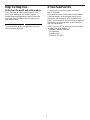
Help Us Help You…
Write down the model and serial numbers.
You’ll find them on a label on the back wall of the
hood. These numbers are also on the Consumer
Product Ownership Registration Card that came with
your hood. Before sending in this card, please write
these numbers here:
Model Number Serial Number
Use these numbers in any correspondence or service
calls concerning your hood.
If You Need Service
To obtain service, see your warranty on the back
page of this guide.
We’re proud of our service and want you to be pleased.
If for some reason you are not happy with the service
you receive, here are steps to follow for further help.
FIRST, contact the people who serviced your appliance.
Explain why you are not pleased. In most cases, this
will solve the problem.
NEXT, if you are still not pleased, write all the details—
including your phone number—to:
Manager, Customer Relations
GE Appliances
Appliance Park
Louisville, KY 40225
11

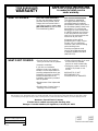
WHAT IS COVERED
FULL ONE-YEAR WARRANTY
For one year from date of original
purchase, we will provide, free of
charge, parts and service labor in
your home to repair or replace
any
part of the hood
that fails because
of a manufacturing defect.
*******************
This warranty is extended to
the original purchaser and any
succeeding owner for products
purchased for ordinary home use in
the 48 mainland states, Hawaii and
Washington, D.C. In Alaska the
warranty is the same except that it
is LIMITED because you must pay
to ship the product to the service
shop or for the service technician’s
travel costs to your home.
All warranty service will be
provided by our Factory Service
Centers or by our authorized
Customer Care
®
servicers during
normal working hours.
Should your appliance need
service, during warranty period
or beyond, call 800-GE-CARES
(800-432-2737).
WHAT IS NOT COVERED
• Service trips to your home to
teach you how to use the product.
• Improper installation.
If you have an installation
problem, contact your dealer or
installer. You are responsible for
providing adequate electrical, gas,
exhausting and other connecting
facilities as described in the
Installation Instructions provided
with the product.
• Replacement of the replaceable
filters.
• Replacement of house fuses or
resetting of circuit breakers.
• Failure of the product if it is used
for other than its intended
purpose or used commercially.
• Damage to product caused by
accident, fire, floods or acts
of God.
WARRANTOR IS
NOT
RESPONSIBLE FOR
CONSEQUENTIAL DAMAGES.
Some states do not allow the exclusion or limitation of incidental or consequential damages, so the above limitation or exclusion
may not apply to you. This warranty gives you specific legal rights, and you may also have other rights which vary from state to state.
To know what your legal rights are in your state, consult your local or state consumer affairs office or your state’s Attorney General.
Warrantor: General Electric Company
If further help is needed concerning this warranty, write:
Manager—Customer Relations, GE Appliances, Louisville, KY 40225
JN327
JV327
JV337
JV347
Part No. 164D3333P051-5
Pub No. 49-8809-5
945-0626-005
10-00 JR
YOUR RANGE HOOD
WARRANTY
Staple sales slip or cancelled check
here. Proof of original purchase date
is needed to obtain service
under warranty.
Printed in the United States
-
 1
1
-
 2
2
-
 3
3
-
 4
4
-
 5
5
-
 6
6
-
 7
7
-
 8
8
-
 9
9
-
 10
10
-
 11
11
-
 12
12


