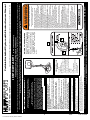
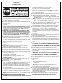
Huffy MCM108DB User manual

Category
Fitness, gymnastics & weight training
Type
User manual

Huffy MCM108DB is a portable basketball system with an elevator. It is designed for home recreational use and not excessive competitive play. The minimum operational height is 6' 6" (1.98 m) to the bottom of the backboard. The system comes with a 48" tempered glass backboard, a breakaway rim, and an adjustable height mechanism. It can be filled with either water or sand for stability and includes a tie-down stake for added security. The system is easy to assemble and disassemble, making it convenient for storage and transportation.

Huffy MCM108DB is a portable basketball system with an elevator. It is designed for home recreational use and not excessive competitive play. The minimum operational height is 6' 6" (1.98 m) to the bottom of the backboard. The system comes with a 48" tempered glass backboard, a breakaway rim, and an adjustable height mechanism. It can be filled with either water or sand for stability and includes a tie-down stake for added security. The system is easy to assemble and disassemble, making it convenient for storage and transportation.

1
12/01 P/N 211488E
WARNING
FAILURE TO FOLLOW THESE WARNINGS MAY RESULT
IN SERIOUS INJURY AND/OR PROPERTY DAMAGE.
Owner must ensure that all players know and follow
these rules for safe operation of the system.
DO NOT HANG on the rim or any part of the system
including backboard, support braces or net.
During play, especially when performing dunk type
activities, keep player's face away from the backboard, rim
and net. Serious injury could occur if teeth/face come in
contact with backboard, rim or net.
Do not slide, climb, shake or play on base and/or pole.
After assembly is complete, fill system completely with
water or sand and stake to the ground. Never leave system
in an upright position without filling base with weight, as
system may tip over causing injuries.
When adjusting height or moving system, keep hands and
fingers away from moving parts.
Do not allow children to move or adjust system.
During play, do not wear jewelry (rings, watches, necklaces,
etc.). Objects may entangle in net.
Surface beneath the base must be smooth and free of
gravel or other sharp objects. Punctures cause leakage and
could cause system to tip over.
Keep organic material away from pole base. Grass, litter,
etc. could cause corrosion and/or deterioration.
Check pole system for signs of corrosion (rust, pitting,
chipping) and repaint with exterior enamel paint. If rust has
penetrated through the steel anywhere, replace pole
immediately.
Check system before each use for proper ballast, loose
hardware, excessive wear and signs corrosion and repair
before use.
Check system before each use for instability.
Do not use system during windy and/or severe weather
conditions; system may tip over. Place system in the
storage position and/or in an area protected from the wind
and free from personal property and/or overhead wires.
Never play on damaged equipment.
See instruction manual for proper installation and
maintenance.
When moving system, use caution to keep mechanism from
shifting.
Keep pole top covered with cap at all times.
Do not allow water in tank to freeze. During sub-freezing
weather add non-toxic antifreeze, sand or empty tank
completely and store. (Do not use salt.)
Use extreme caution if placing system on sloped surface.
System may tip over more easily.
201241 2/99
In the U.S.:1-800-558-5234 and Canada: 1-800-284-8339
Toll-Free Customer Service Number for U.S: 1-800-558-5234, For Canada: 1-800-284-8339, For Europe: 00 800 555 85234 (Sweden: 009 555 85234),
For Australia: 1-800-333 061 - Internet Address: http://www.huffysports.com
Most injuries are caused by misuse and/or not following instructions.
Use caution when using this system.
If using a ladder during assembly, use extreme caution.
Two (2) people are recommended for this operation.
Check base regularly for leakage. Slow leaks could cause system to
tip over unexpectedly.
Seat the pole sections properly (if applicable). Failure to do so could
allow the pole sections to separate during play and/or transport of the
system.
Climate, corrosion or misuse could result in system failure.
Minimum operational height is 6' 6" (1.98 m) to the bottom of
backboard.
This equipment is intended for home recreational use only and NOT
excessive competitive play.
Read and understand the warning label affixed to pole. Label is
shown on page 1.
The life of your basketball pole depends on many conditions. The
climate, placement of the pole, the location of the pole, exposure to
corrosives such as pesticides, herbicides or salts are all important.
If technical assistance is required, contact Huffy Sports.
Adult supervision is recommended when adjusting height.
FAILURE TO FOLLOW THESE SAFETY INSTRUCTIONS MAY
RESULT IN SERIOUS INJURY, PROPERTY DAMAGE AND WILL
VOID WARRANTY.
Owner must ensure that all players know and
follow these rules for safe operation of the system.
To ensure safety, do not attempt to assemble this system without
following the instructions carefully. Proper and complete assembly,
use and supervision is essential for proper operation and to reduce
the risk of accident or injury. A high probability of serious injury
exists if this system is not installed, maintained, and operated
properly. Check entire box and inside all packing material for parts
and/or additional instructional material. Before beginning
assembly, read the instructions and identify parts using the
hardware identifier and parts list in this document.
For more information on assembly, placement, proper use and
maintenance, visit The American Basketball Council website at
http://www.smarthoops.com.
SAFETY INSTRUCTIONS
64
REQUIRED TOOLS AND
MATERIALS:
Two People
Tape Measure
Wood Board (Scrap)
Wrenches: (Two of Each) 7/16”,
1/2”, 9/16”, 3/4” or Large and
Small Adjustable Wrenches
Sawhorse or Support Table
Garden Hose or Sand (300 lb.)
(136 kg)
Hammer
Tape
Phillips Screwdriver
1/2” & 9/16” Extended Deep
Socket w/ Extension
Recommended
© COPYRIGHT 2001 by HUFFY SPORTS
WRITE IN YOUR MODEL NUMBER:_________________
Customer Service Center • N53 W24700 South Corporate Circle • Sussex, WI 53089 • U.S.A.
A Huffy Company
Portable Basketball System with Elevator-Owners Manual
IMPORTANT!
In U.S. and Canada only:
Have questions?...don’t go back to the store!
We appreciate your purchasing one of our many fine products. We are sure that you will be very satisfied with your selection. Although great care and effort have been taken, occasionally problems may occur. To
ensure prompt and correct handling of any problems, or to answer any questions, please contact our Toll-Free Customer Service Number listed below. Service will be quicker if you have your Model Number
(found on carton) and assembly instructions ready when calling. PLEASE WRITE YOUR MODEL NUMBER IN THE SPACE PROVIDED ABOVE.
NOTICE TO ASSEMBLERS
ALL Huffy Sports basketball Systems,
including those used for DISPLAYS,
MUST be assembled and ballasted with
sand or water according to instructions.
Failure to follow instructions could result
in SERIOUS INJURY. It is NOT
acceptable to devise a makeshift weight
system.
The NBA and individual NBA member team identifications reproduced on this product are
trademarks and copyrighted designs, and/or other forms of intellectual property, that are the
exclusive property of NBA Properties, Inc. and the respective NBA member teams and may not
be used, in whole or in part, without the written consent of NBA Properties, Inc.
2
P/N 211488E 12/01
* You may have extra parts with this model.
HARDWARE IDENTIFIER
Item #7 (1)
Item #8 (1)
Item #12 (1)
Item #13 (12)*
Item #17 (14)
Item #14 (2)
Item #16 (2)
Item #10 (3)*
Item #21 (2)
Item #30 (2)
Item #34 (2)
Item #31 (12)*
Item #18 (2)
Item #26 (1)
Item #36 (2)
Item #38 (3)
Item #37 (2)
12/01 P/N 211488E
3
HARDWARE IDENTIFIER (continued)
Item #40 (5)
Item #39 (2)
Item #41 (3)
Item #49 (1)
Item #43 (2)
Item #44 (2)
Item #50 (1)
Item #58 (9)
Item #59 (2)
Item #46 (1)
Item #52 (1)
Item #61 (1)
Item #68 (4)*
Item #69 (2)
Item #53 (1)
4
P/N 211488E 12/01
Item
Qty. Part No. Description
1 1 206615 Tank, (Black)
2 1 200628 Wheel Axle, 11-3/4 Long
3 4 226401 Wheel, 4 “ (Black)
4 1 900107 Top Pole Section
5 1 900106 Middle Pole Section
6 1 900105 Bottom Pole Section
7 1 202820 Rod, 3/8 O.D. x 4-3/4 Long
8 1 206934 Eyebolt, 3/8-16 x 2 1/2 Long
9 1 206949 Pivot Bracket, Upper
10 3* 203063 Nylon Insert Lock Nut, 3/8-16
11 2 906206 Strut, 1” O.D. x 43 Long
12 1 202662 Bolt, Hex Head, 5/16-18 x 4-1/2 Long
13 12* 203218 Washer, Flat, 3/8 I.D.
14 2 203220 Nylon Insert Lock Nut, 5/16-18
15 1 200629 Anchor, T-Strap
16 2 203798 Bolt, Hex Flange, 5/16-18 x 1-1/2 Long
17 14 203100 Nut, Hex Flange, 5/16-18
18 2 203103 Carriage Bolt, 5/16-18 x 2 Long
19 1 900223 Wheel Bracket
20 1 206948 Pivot Bracket, Lower
21 2 206252 Bolt, Hex Head, 3/8-16 x 1 Long
22 1 206956 Disc, 5" O.D. x 13/32 I.D., Plastic
23 1 906606 Handle Bar
24 1 206940 Axle
25 2 206938 Push Cap
26 1 203330 Bolt, Hex Head, 3/8-16 x 4-1/2 Long
27 1 204849 Handle, Front, Plastic
28 1 204849 Handle, Back, Plastic
29 1 206990 Reinforcement Bracket
30 2 203217 Carriage Bolt, 5/16-18 x 1-1/2 Long
31 12* 200120 Clip, Net Holder, (Red)
200121 Clip, Net Holder, (Black)
32 1 Rim
33 1 200209 Bracket, Pole Mount
34 2 203053 Bolt, Carriage, 5/16-18 x4 Long
Item
Qty. Part No. Description
35 2 900103 Bracket, Backboard Support
36 2 206360 Bolt, Hex Head, 3/8-16 x 2.625 Long
37 2 200874 Spacer, Steel .402 I.D. x .50 O.D. x 1.5 Long
38 3 201124 Nut, 3/8-16
39 2 201642 Spacer .530 I.D. x .625 Long
40 5 206340 Nut 1/2-13
41 3 201640 Bolt 1/2-13 x 7-1/4 Long
42 2 900183 Lower Elevator Tubes - Long
43 2 201681 Spacer .530 I.D. x.63 O.D. x .875 Long
44 2 206304 Bolt 1/2-13 x 6-5/16 Long
45 2 900184 Upper Elevator Tubes - Short
46 1 200516 Vinyl Bolt Cover, 5/16
47 1 207103 Cap, Pole Top
48 1 204838 Spring, Silver
49 1 203112 Bolt, 5/16-18 x 6-1/2 Long
50 1 200830 Bolt, 3/8-16 x 7-1/2 Long
51 1 900006 Adjustment Tube
52 1 200214 Locking Pin
53 1 200215 Cross Pin
54 1 200211 Left Handle
55 1 200210 Right Handle
56 1 200257 Spring
57 1 200212 Trigger
58 9 204804 Screw, Phillips Head, 3/4 Long
59 2 202862 Spacer .563 I.D. x 1.19 Long
60 1 908008 Adjustment Rod
61 1 202739 Bolt 5/16-18 x 1-3/4 Long
62 1 203124 Stake, Tie Down
63 2 203617 Plug Cap
64 1 211261 Label, Height Adjustment and Moving
65 1 204281 Net
66 1 204872 Label, Height Indicator
67 1 200627 Wheel Carriage
68 4* 205528 Bolt, Hex Flange, 5/16-18 x 1 Long
69 2 201651 Spacer, Wheel Axle
WARRANTY CARD:
Please remember to complete your product
registration form either
on-line at: www.huffysports.com/warrantycard
or mail-in the enclosed postcard.
WARNING: IF YOUR SYSTEM IS EQUIPPED WITH AN ACRYLIC
BACKBOARD, EXAMINE BACKBOARD FOR ANY DAMAGE THAT MAY
HAVE OCCURRED DURING SHIPMENT. CRACKS IN THE BACKBOARD
COULD RESULT IN SUDDEN BREAKAGE. IF BACKBOARD IS DAMAGED
IN ANY WAY PRIOR TO OR AFTER ASSEMBLY, CALL TOLL-FREE
NUMBER FOR FREE REPLACEMENT:
U.S. 1-800-558-5234; CANADA: 1-800-284-8339; http://www.huffysports.com
PARTS LIST - See Hardware Identifier
12/01 P/N 211488E
5
INSTRUCTIONS
IMPORTANT! WRITE MODEL NUMBER FROM BOX ONTO PAGE 1 OF
THIS OWNERS MANUAL
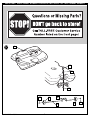
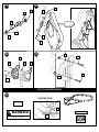
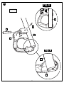
1. Remove all contents from underside of tank. Keep tank (1) bottom side
up. Install wheel axle (2) through wheel carriage (67) and install wheels
(3) onto wheel axle (2) with spacers (69) as shown. Secure wheel bracket
as shown, a deep socket is recommended.
IMPORTANT! DO NOT OVER TIGHTEN.
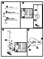
2. Correctly identify each pole section and mark indicated distance from ends
with tape as shown.
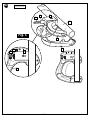
3. Align pole top and middle pole sections as shown using alignment mark
and hole.
IMPORTANT! Holes in top (4) and middle pole (5) sections MUST
align to correctly position elevator system toward playing surface.
Bounce pole top (4) and middle section (5) together as shown until they
no longer move toward taped reference mark. NOTE: Pole sections
should have a 3-1/2" (9 cm) minimum overlap.
4. IMPORTANT! Holes in top (4) and bottom pole (6) sections MUST
align to correctly position elevator system toward playing surface.
Add bottom pole section (6) to assembly as shown using alignment mark
and hole, and bounce until completely tight. Once assembled, pole
sections CAN NOT be separated! NOTE: Pole sections should have a
3-1/2" (9 cm) minimum overlap.
5. Install rod (7) through holes in bottom pole section (6) and eyebolt (8).
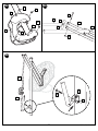
6. Insert pole assembly into tank assembly as shown. Secure pole assembly
with upper pivot bracket (9) and lock nut (10).
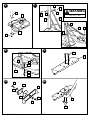
7. Secure base struts (11) to pole using bolt (12), washers (13), and nut (14),
as shown. Place vinyl bolt cover (46) over exposed bolt threads. Rotate
the non-secured ends of base struts (11) as shown.
8. Secure base struts (11) to base using bolt (16), washers (13), and
nut (17).
9. Insert carriage bolts (18) into middle set of holes on wheel bracket (19) as
shown.
10. Attach lower pivot bracket (20) to wheel bracket (19) using bolt (21),
washers (13), disc (22), and nut (10) as shown.
11. Attach handle bar (23) to wheel bracket assembly using nuts (17) as
shown.
12. Install wheels (3) onto axle (24) and wheel bracket assembly with push
caps (25) as shown.
13. Attach wheel bracket assembly to base assembly using bolt (26), washers
(13), and nut (10) as shown.
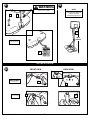
14. NOTE: Two people recommended for this step. Carefully reposition
entire assembly to upright position.
Attach front of plastic handle (27) to back of plastic handle (28) around
handle bar (23) using self-tapping screws (58) as shown.
IMPORTANT! Front of plastic handle (27) should face outward, away
from pole assembly.
15. Insert bolts (30) through plastic handle assembly, handle bar (23) and
attach nuts (17) as shown. Tighten completely.
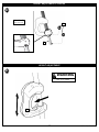
16. Install net clips (21).
The Quick Clip™ rapid release net system lets the net pull away from the
rim. This reduces the risk of player injury or property damage. However,
improper installation or a ball making contact at an odd angle may
disengage the net clip from the goal rim. Usually, the clip is reinstalled
with little or no problem. We hope that you agree this inconvenience is
minor when compared to the safety of the players. Quick Clip: US Patent
No. 5,792,010/5,795,253
The two outer hooks on net clip must face towards inside of goal rim.
Insert larger hole in net clip onto rim stud, push down on net clip, then
slide net clip right, locking or snapping securely into position (clips must
"snap" into place to insure a secure fit).
NOTE: Net clips should not slide with ease. It is very important that the
net clips are in the locked position before going on to next step.
WARNING: USE OF THIS PRODUCT WITHOUT PROPER
INSTALLATION OF NET CLIPS, OR WHEN ALL NET CLIPS ARE NOT
PRESENT COULD RESULT IN BODILY HARM. BE SURE TO FOLLOW
DIRECTIONS CAREFULLY.
17. Attach elevator bracket (33) to middle pole section (5) using bolts (34),
reinforcement bracket (29), and nuts (17) as shown.
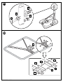
18. Attach backboard support brackets (35) to the backboard frame using
bolts (36), spacers (37), and nuts (38) as shown.
19. Attach lower elevator tubes (42) to backboard support brackets (35) using
spacers (39), bolt (41), and nut (40) as shown. NOTE: Rim mounting
nuts and bolts supplied with rim hardware. NOTE: DO NOT use washers
here on spring return style rims.
20. Attach upper elevator tubes (45) to backboard support brackets (35) using
spacers (43), bolt (44), and nut (40) as shown.
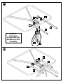
21. A.Attach upper and lower elevator tubes (45, 42) to upper pole
section (4) using bolts (44, 41) and nuts (40) as shown. Attach pole
cap (48) as shown.
B.Attach counterbalance spring (48) to upper elevator tubes (45) with bolt
(49) and nut (14) in location shown. Stretch spring to lower elevator
tubes (42) and attach with hardware (50, 10) as shown.
NOTE: Slide counterbalance spring against elevator tubes.
22. Insert locking pin (52) into bracket on adjustment tube (51). Insert cross
pin (53) through hole in bracket and locking pin (52) as shown in
figure A. Fit left handle (54) onto adjustment tube (51) so the bottom of
adjustment tube (51) sits on the two small ribs of the handle as shown in
figure B.
23. Insert spring (56) into back of locking pin (52) as shown. Spring (56)
should rest between two small ribs at the back of the plastic handle as
shown in Figure C. Insert top of trigger (57) into bracket on the
adjustment tube (51) as shown. The plastic post of the handle pieces
should go through the hole in bottom of trigger (57) and hold it into place
as shown.
24. Finish handle assembly by attaching right handle (55) using screws (58)
as shown.
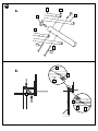
25. Attach adjustment tube (51) to lower elevator tubes (42) using bolt (41),
spacers (59), and nut (40) as shown.
26. Insert lower adjustment rod (60) into bottom of adjustment tube (51), pull
trigger to allow lower adjustment rod (60) to move about mid-way into
adjustment tube (51), release trigger so the lower adjustment rod (60)
locks into position midway inside adjustment tube (51). Attach lower
adjustment rod (60) to elevator bracket (33) using bolt (61) and nut (14) as
shown.
WARNING: TWO PERSON MINIMUM REQUIRED FOR THIS
PROCEDURE. NOT FOLLOWING RECOMMENDATION MAY RESULT
IN BODILY INJURY.
WARNING: DO NOT LEAVE ASSEMBLED UNIT UNATTENDED WHEN
EMPTY, MAY TIP OVER.
27. Roll the completed assembly to the desired playing area. Insert the
T-strap (15) through the slot on the back of the base as shown. Secure
the unit to ground by twisting the tie down stake (62) into the ground and
hooking the T-strap (15) onto the tie down stake (62). Fill tank with 33
gallons of water.
IMPORTANT! Add two gallons (7.6 Liters) of non-toxic antifreeze in
sub-freezing climates.
WARNING: DO NOT LEAVE ASSEMBLY UNATTENDED WHEN
EMPTY, MAY TIP OVER.
28. Apply the height adjustment and moving label (64) to the front of the pole
as shown.
29. Install net (65).
IMPORTANT! Make sure net is held by all three hooks on the net
clip.
A.Slide net into outer hook as shown.
B.Slide net into second outer hook creating a loop as shown. Push loop
to back of clip.
C.Pull loop up and through back of clip, snapping over the middle hook.
D.Pull net down to make sure it is held securely by all three hooks.
NOTE: If net releases during normal play, net was improperly installed.
Please review instructions to install net properly.
30. Lock elevator system into highest position (so the backboard is as high as
it will go). Apply 10 ft. height indication sticker (66) to adjustment tube
(51) directly below arrow on handle as shown. Move elevator system to
the next position and apply the 91/2 ft. sticker. Repeat until all height
settings have been labeled. (8-10ft.)
31. Pull trigger (57). Move elevator system up or down to desired height,
release trigger (57) to lock system into one of the five height settings.
WARNING: DO NOT ALLOW CHILDREN TO ADJUST HEIGHT.
6
P/N 211488E 12/01
IMPORTANT! WRITE MODEL NUMBER FROM BOX ONTO PAGE 1 OF THIS OWNERS MANUAL
1
1.
2
69
69
3
3
67
21
13
38
12/01 P/N 211488E
7
3.2.
4
5
6
4
5
4
6
5
5.
4.
5
5
8
7
6
6
8
P/N 211488E 12/01
16
11
13
1
18
19
13
17
21
13
20
22
19
13
10
23
17
9
10
1
12
13
13
11
6
6
11
1
11
14
46
6
6. 7.
8.
9.
11.10.
SEE TEXT PAGE
WARNING
12/01 P/N 211488E
9
25
3
24
3
25
10
13
26
13
58
28
23
27
17
30
NET CLIP INSTALLATION
OUTSIDE VIEW
31
32
OUTER HOOKS
Note
(See Text Page)
16.
14. 15.
12. 13.
SEE TEXT PAGE
WARNING
17
30
58
10
P/N 211488E 12/01
33
34
29
17
17.
35
37
37
38
35
35
36
18.
12/01 P/N 211488E
11
41
42
42
68
68
39
39
35
40
19.
20.
Refer To
Instructions
Included With Rim
Hardware For Rim
Assembly.
45
45
44
43
35
40
43
12
P/N 211488E 12/01
41
47
42
42
45
45
44
40
40
A.
B.
48
21.
10
42
50
49
14
45
12/01 P/N 211488E
13
53
51
54
52
IMPORTANT!
SEE TEXT PAGE
22.
Fig. A
Fig. B
53
52
51
51
54
14
P/N 211488E 12/01
51
56
52
53
57
54
IMPORTANT!
SEE TEXT PAGE
23.
Fig. C
54
52
56
53
12/01 P/N 211488E
15
60
51
41
59
59
51
40
42
45
58
58
58
58
54
55
58
24. 25.
26.
14
61
33
16
P/N 211488E 12/01
NET INSTALLATION
63
15
27. 28.
29.
IMPORTANT!
SEE TEXT PAGE
10 ft.
(3.05 m)
64
IMPORTANT!
(See Text Page)
Note
(See Text Page)
FRONT VIEW
65
BACK VIEW
65
32
A
B
C
D
32
62
SEE TEXT PAGE
WARNING
Peel protective film from
surface of acrylic
backboard prior to use.
NOTE:
12/01 P/N 211488E
17
HEIGHT ADJUSTMENT
HEIGHT ADJUSTMENT STICKERS
30.
31.
IMPORTANT!
SEE TEXT PAGE
66
51
57
SEE TEXT PAGE
WARNING
  • Page 1 1
  • Page 2 2
  • Page 3 3
  • Page 4 4
  • Page 5 5
  • Page 6 6
  • Page 7 7
  • Page 8 8
  • Page 9 9
  • Page 10 10
  • Page 11 11
  • Page 12 12
  • Page 13 13
  • Page 14 14
  • Page 15 15
  • Page 16 16
  • Page 17 17

Huffy MCM108DB User manual

Category
Fitness, gymnastics & weight training
Type
User manual

Huffy MCM108DB is a portable basketball system with an elevator. It is designed for home recreational use and not excessive competitive play. The minimum operational height is 6' 6" (1.98 m) to the bottom of the backboard. The system comes with a 48" tempered glass backboard, a breakaway rim, and an adjustable height mechanism. It can be filled with either water or sand for stability and includes a tie-down stake for added security. The system is easy to assemble and disassemble, making it convenient for storage and transportation.

Ask a question and I''ll find the answer in the document

Finding information in a document is now easier with AI