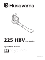
Husqvarna 225 HBV User manual
- Category
- Air blowers/dryers
- Type
- User manual

225 HBV EPA Version
Operator´s manual
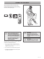
Read the operator’s manual carefully and
make sure that you understand the contents
before using the blower.
101 90 68-95

Svenska – 31
Sve-5 225/232/235 Bruk 97-11-25, 08.4631

English – 1
CONTENTS
Introduction .........................................2
Key to symbols....................................3
Safety instructions..............................4
Description...........................................6
Fuel handling.....................................11
Starting and stopping .......................13
Using the blower ...............................14
Maintenance.......................................18
Technical data....................................25
Maintenance, replacement, or repair of the emission
control devices and systems may be performed by any
nonroad engine repair establishment or individual.

2 – English
INTRODUCTION
!
WARNING!
Under no circumstances may the
design of the machine be modified
without the permission of the
manufacturer. Always use genuine
accessories. Non-authorised
modifications and/or accessories
can result in serious personal
injury or the death of the operator
or others.
Your warranty does not cover
damage or liability caused by the
use of non-authorized accessories
or replacement parts.
Husqvarna AB has a policy of continuous product
development and therefore reserves the right to
modify the design and appearance of products
without prior notice.
This decal certify that the product has been
approved in accordance with American
exhaust emission requirements EPA PH1.
IMPORTANT ENGINE INFORMATION
HUSQVARNA AB HUSKVARNA SWEDEN
TWC
REFER TO OPERATOR`S MANUAL FOR
MAINTENANCE SPECIFICATIONS AND ADJUSTMENTS.
FOR SMALL NON - ROAD ENGINES.
EPTHIS ENGINE CONFORMS TO U.S. PH1A
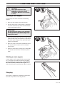
This operator’s manual describes in detail how to
use and service the blower and how to carry out
regular maintenance. It also describes which meas-
ures should be taken to achieve maximum safety
while operating the blower, how the safety devices
work and how they should be serviced.
Note! The section of the manual that deals with
safety, must be read and understood by all persons
who come in contact with the blower.
This operator’s manual has been written for those
who need guidance when it comes to fault tracing,
thorough servicing and carrying out corrective
maintenance of the blower.
There are warning symbols on the blower. These
are illustrated on page 3. Should any of the warning
symbols on the blower become disfigured or worn,
new ones should be ordered and fitted to the blower
as soon as possible. Note that some of the warning
symbols are molded in certain components of the
blower.
The blower is used for blowing away or vacuuming
up leaves and other debris on the ground. When
operating the blower, the operator must stand with
both feet firmly on the ground.

English – 3
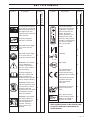
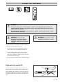
KEY TO SYMBOLS
Symbol Description Location
Operator’s manual
Blower
Symbol Description Location
Blower
The blower operator
must make sure that no
bystanders or animals
come nearer than 10
metres. Whenever
several operators are
working in the same
work area, they should
maintain a safe distance
of at least 10 metres
from one another.
Choke.
Refueling.
Stop switch.
The manufacturer’s
warrantee for this
product meets safety
requirements according
to:
•The Machine Directive
•The EMC Directive
•The Low Voltage
Directive
Instructions on how to
open the inspection
cover.
Noise pressure level
measured at 15 metres
distance according to
ANSI B175.2-1996.
Operator’s manual
X
X
X
XX
XX
XX
XX
XX
X X
X
X
X
XX
X
X
70
dB (A)
per ANSI B175. 2-1996
STOP
Other symbols/decals on the machine refer
to special certification requirements for
certain markets.
Checks and/or mainten-
ance shall be carried out
after having switched off
the engine. The stop
switch must be set to the
STOP position.
Cleaning at regular
intervals is required.
Approved protect gogg-
les or visor must be
worn.
Approved protect gogg-
les or visor and ear
protection must be worn.
WARNING! The blower
can be dangerous!
Careless or improper
use can cause serious,
even fatal injury.
Read the operator’s
man-ual carefully and
make sure that you
understand the contents
before using the blower.
WARNING! Make sure
that the inspection cover
is locked in the closed
position or that the
vacuum tube is mounted
on the blower. Never
touch the impeller.
WARNING! The blower
may throw objects at
high velocity that can
ricochet and hit the
operator. This may
cause serious eye
damage.

4 – English
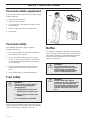
Personal safety equipment
Fuel safety
!
Special safety instructions apply to the type of fuel
used for the blower. These instructions are specified
under ”Fuel handling” on pages 11 and 12.
The following instructions apply to persons
operating the blower:
1. The operator shall have read and understood
the contents of this manual.
2. Do not wear loose clothing, scarves or neck
chains or let long hair hang loose, since these
can be drawn into rotating parts of the blower
and cause injury.
3. Do not operate the blower while under the
influence of alcohol, drugs or when you are
tired.
4. Do not allow minors to operate the blower.
SAFETY INSTRUCTIONS
WARNING!
The fuel used to run the blower
has the following dangerous
charact-eristics:
1. Volatile liquid, its vapor and
exhaust fumes are poisonous.
2. Direct contact can cause skin
irritation.
3. It is extremely combustible.
Personal safety
Persons who use the blower shall wear the following
safety equipment:
1. Approved ear protection.
2. Approved eye protection.
3. Face mask when operating the blower in dusty
environments.
4. Boots or work shoes with a non-slip sole.
5. First-aid kit.
Muffler
The muffler is designed to give the lowest possible
noise level and to direct the engine‘s exhaust fumes
away from the operator. Muffler fitted with catalytic
converter is also designed to reduce harmful
exhaust components.
!
WARNING!
The exhaust fumes from the
engine are hot and may contain
sparks which can start a fire.
Never start the machine indoors
or near combustible material!
!
WARNING!
Mufflers fitted with catalytic
converters become extremely hot
during use and after stopping.
This also applies at idling speeds.
Contact can result in burns to the
skin. Be observant to the risk of
fire!
1+2 3
4 5

English – 5
1. Do not allow bystanders or animals to be in the
work area, i.e. 10 metres from the operator.
2. The blower may throw objects at high velocity
that can ricochet and hit the operator. This may
cause serious eye damage.
3. Never point the blower nozzle toward people or
animals.
4. Stop the engine before fitting or dismantling
accessories or other components.
5. Never operate the blower if any of the guards is
missing.
6. Never operate the blower in poorly ventilated
spaces where exhause fumes might otherwise
be inhaled.
7. Stop the engine before refueling.
8. The catalytic muffler is extremely hot while the
blower is running and after it has stopped. The
same applies when the blower is running at
idling speed. Be aware of the danger of fire,
especially while operating the blower near
combustible materials and/or where combustible
fumes are present.
9. Be careful, particurlarly if left hand operation is
applied. Avoid any direct body contact with the
exhaust outlet area.
10. Do not operate the blower while standing on a
ladder or a stand.
Safety equipment
!
WARNING!
The blower must never be used if
any of the safety devices or
guards are missing, damaged or
not in working order.
The blower is equipped with a number of safety
devices and guards for the prevention of accidents.
These are described in the general description of
the blower on page 8.
The safety devices and guards also require regular
inspection and maintenance. These measures and
the interval at which they should be carried out are
specified under ”Maintenance” on pages 23 and 24.
1. Operate the blower only at reasonable hours,
i.e. not early in the morning or late at night when
people might be disturbed. Comply with times
listed in local ordinances. Usual recommend-
ations are 9:00 a.m. to 5:00 p.m. Monday
through Saturday.
2. Operate the blower at the lowest possible
throttle setting to do the job.
3. Check the condition of the blower before opera-
tion, especially the muffler, air intake and air
filter.
4. Use a rake or a broom to loosen ground debris
before blowing.
5. Under dusty conditions, slightly spray the work
area with a hose or use a mister attachment
when water is available.
6. Conserve water by using blowers instead of
hoses for many lawn and garden applications,
including areas such as roof gutters, screens,
patios and gardens etc.
7. Watch out for children, pets, open windows or
freshly washed cars, and blow debris safely
away.
8. Use the full nozzle extension so the air stream
can work close to the ground.
9. After using the blower, clean up and dispose of
debris in trash receptacles
Safety while operating the
blower
Other safety measures
SAFETY INSTRUCTIONS

6 – English
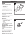
DESCRIPTION
The blower
1. Shoulder strap
2. Throttle trigger
3. Stop switch
4. Throttle lock
5. Shoulder strap ring
6. Anti-vibration system (inside the housing)
7. Fan housing
8. Fuel cap
9. Air filter
10. Choke
11. Inspection cover
12. Cutters
13. Fan impeller
14. Nozzle
15. Blower tube
16. Muffler
17. Start handle
18. Starter device
19. Carburetor adjustment screws
20. Operator’s manual
21. High velocity nozzle.
12
34
5
6
7
10
9
8
18
17
16
19
21
715
14
20
7
13
11
12

English – 7
DESCRIPTION
Accessories
21. Vacuum device with collection components consisting of items 22 - 25 below.
22. Vacuum bag tube.
23. Collection bag.
24. Vacuum tube in two sections.
25. Auxiliary handle.
25
23
22
24
21

8 – English
DESCRIPTION
34
2
!
The muffler is designed to give the lowest possible
noise level and to direct the engine‘s exhaust fumes
away from the operator. Muffler fitted with catalytic
converter is also designed to reduce harmful
exhaust components.
The engine exhaust fumes are hot and can contain
sparks, which may cause fire if they come in contact
with dry or combustible material.
Some blower models, esp. those sold in countries
where the climate is dry, are equipped with spark-
arresting mesh (A). This mesh must be cleaned or
replaced at specific intervals. Check if your blower
muffler has mesh of this type.
Muffler(16)
WARNING!
The muffler is extremely hot while
the engine is running and after it
has stopped. DO NOT TOUCH THE
MUFFLER IF IT IS HOT! This can
cause severe burns.
Safety equipment
The following equipment on the blower is designed
for protecting personnel and materials. These com-
ponents should receive special attention whenever
you operate, inspect and service the blower.
Anti-vibration system (6)
The anti-vibration system is designed to dampen
vibrations transmitted from the engine to the handle.
The anti-vibration system consists of spring-type
mountings, from which the engine is suspended.
Stop switch (3)
The stop switch is used to stop the engine.
The throttle lock prevents inadvertent activation of
the throttle. When the throttle lock is pressed into
the handle (when gripping the handle) the throttle
trigger (2) is disengaged. When the operator releases
his/her grip on the handle, both the throttle trigger
and the throttle lock are reset to their original settings
by means of two spring systems which work inde-
pendently of one another.
Throttle lock (4)
A

English – 9
DESCRIPTION
24
15 14
7 13 12 11
Throttle trigger (2)
The speed and the output of the engine are regul-
ated by the throttle trigger. The throttle lock (4) must
be pressed down before the trigger will actuate the
throttle.
Fan casing (7)
The blower fan casing (7) together with the impeller
(13) provide high performance air discharge.
Inspection cover (11)
An inspection cover is located on the underside of
the fan casing. Removal of this cover allows access
for cleaning and inspecting the impeller. The inspec-
tion cover can only be opened by means of tools.
If the vacuum tube is used, it must be fitted to the
opening in the inspection cover as shown on page
16.
Nozzle (14) and blower tube (15)
The nozzle and the blower tube have a bayonet
mount for connection to the blower. Air is channeled
through the blower tube to the nozzle, where the air
discharge velocity increases and the air stream dis-
charge pattern is formed to provide best perform-
ance.
WARNING!
Never start the blower if the
inspection cover is not closed, is
damaged or cannot be closed.
(Exception: When the vacuum tube
is fitted).
!
Cutters (12)
Two cutters are fastened to the impeller. The cutters
are there to mulch leaves and other debris, that
have been vacuumed, before they enter the fan
inlet.
Other equipment

10 – English
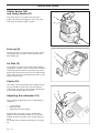
DESCRIPTION
17
18
8
9
19
10
Starter device (18)
and starter handle (17)
The starter device is located at the top on the
engine shrouding and engages in the crank shaft
only when the starter handle is pulled.
Fuel cap (8)
Air filter (9)
The fuel cap (14) is located at the top of the engine
shrouding and has a gasket, which prevents fuel
from leaking out.
The air filter consists of foam-rubber filter medium,
integrated in a plastic casing. The air filter should be
cleaned at specific intervals. Otherwise, the power
blower will consume too much fuel, the performance
will be reduced and an oily deposit may form on the
spark plug electrodes.
Choke (10)
Adjusting the carburetor (19)
The choke is located at the top of the engine shroud-
ing and should be used every time the engine is
cold-started. The choke is de-activated automatical-
ly when the throttle trigger is pressed.
There are three adjusting screws for adjusting the
carburetor:
• Low speed jet
• High speed jet
• Adjustment screw for idling
Adjusting the carburetor involves adapting the
engine to local operating conditions, e.g. climate,
altitude, gasoline and type of two-stroke engine oil
used.
For details about carburetor adjustment, see page
18.

English – 11
Fuel mixture
WARNING!
Allow adequate ventilation while
handling fuel.
NOTE!
The machine is fitted with a two-stroke engine and
must always be run on a mixture of gasoline and two-
stroke oil. It is important to measure the quantity of oil
accurately, to ensure the correct mixture ratio. Small
discrepancies in the amount of oil have a great bearing
on the proportions of the fuel mixture when mixing
small amounts of fuel.
!
FUEL HANDLING
Gasoline
NOTE!
Always use an oil-mixed quality gasoline (at least 87
octane). If your machine is equipped with a catalytic
converter,
(see “technical data”)
an unleaded, oil mixed
quality gasoline should always be used. A leaded
gasoline will destroy the catalytic converter.
• This engine is certified to operate on
unleaded gasoline.
• The lowest recommended octane rating is 87. If
you run the engine on lower octane rating than
87 so-called “knocking“ can occur. This leads to
an increased engine temperature, which can
result in a serious engine breakdown.
• When working at continuous high revs a higher
octane rating is recommended.
Two-stroke oil
• For the best performance, use HUSQVARNA
two-stroke oil, which has been specially
developed for Husqvarna two-stroke engines.
Mixing ratio: 1:50 (2%).
• If HUSQVARNA two-stroke oil is not available,
you may use another two-stroke oil of good
quality that is intended for air-cooled engines.
Contact your dealer when selecting an oil.
• Never use two-stroke oil intended for water-
cooled marine outboard motors, so-called
outboard oil.
• Never use oil intended for four-stroke engines.

12 – English
Olja • Olje
Olie • Öljyä
Lit.
5
10
15
20
2%(1:50)
0,10
0,20
0,30
0,40
Bensin
Bensin
Benzin
Bensiiniä
Lit.
O
FUEL HANDLING
Mixture
• Always mix gasoline and oil in a clean container
intended for fuel.
• Always start by filling half the quantity of gasoline
required. Then add the entire oil quantity. Mix
(shake) the fuel mixture. Fill the remaining
quantity of gasoline.
• Mix (shake) the fuel mixture carefully before filling
in the machine‘s fuel tank.
• Do not mix more than max. one month’s supply of
fuel.
• If the machine is not used for a long period of
time, the fuel tank should be emptied and cleaned.
• This engine is certified to operate on unleaded
gasoline.
!
WARNING!
The catalytic converter muffler
gets very hot during and after use.
This also applies during idling. Be
aware of the fire hazard, especially
when handling the saw near
flammable substances or vapours.
!
WARNING!
The following precautions reduce
the risk of fire:
Do not smoke or place any
sources of heat in the vicinity of
the fuel. Never refuel when the
engine is running. Always stop the
engine and let it cool for a few
minutes before refuelling. Open
the fuel cap slowly when fuelling
so that any over pressure is
released slowly. Tighten the fuel
cap carefully after refuelling.
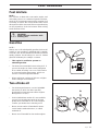
Always move the machine from the
fuelling place before starting.
• Clean around the fuel cap. Contamination in the
tank can disrupt operations.
• Ensure that the fuel is well mixed by shaking the
container before filling the tank.
Fuelling
Gasoline Oil
Min. 3 m (10 ft)

English – 13
STARTING AND STOPPING
WARNING!
Never start the blower if the
inspection cover is not closed, is
damaged or cannot be closed.
(Exception: When the vacuum tube
is fitted).
!
A cold engine should be started in the following
manner:
1. Move the stop switch to the start position.
2. Set the choke to the choke position. Setting the
chock will automatically set the throttle damper
to the start throttle position.
Starting a cold engine
IMPORTANT!
Do not pull out the starter cord completely
and do not release the starter handle from
the fully pulled out position. Doing so will
damage the starter
Stopping
The engine is stopped by switching off the ignition.
Move the stop switch to the stop position..
Starting a warm engine
A warm engine can be started in the same manner
as a cold engine, but with the following exception:
Set the throttle to the start position by first moving
the choke forward, and then back again. The
choke should not be used when the engine is warm.
3. Press the blower against the ground andpull the
starter handle slowly until resistance is felt (when
the starter pawls engage). Then pull it with quick,
vigorous movements.
4. Move the choke control back immediately when
the engine ignites and proceed according to
item 3 above.
5. When the motor starts, rapidly give it full throttle.
The throttle latch will then automatically disen-
gage.

14 – English
USING THE BLOWER
WARNING!
When fitting the blower tube and
nozzle, the engine must be
switched off and the stop switch
must be in the stop position.
!
The blower tube and nozzle have a bayonet mount.
Fit them in the following manner:
1. Press the blower tube (15) against the blower air
outlet and turn it 90 degrees until a snap is
heard.
2. Fit the nozzle (14) onto the tube (15), and turn it
90 degrees until a snap is heard.
To blow away debris on the
ground
Fitting the blower tube and nozzle
on the blower
Blowing
Before you begin blowing, put on the required safety
equipment.
WARNING!
When working with the blower,
wear the required protecting
equipment:
1. Hearing protection.
2. Eye protection.
3. Face mask in dusty environ-
ments.
!
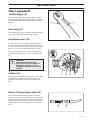
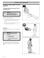
When operating the blower, the blower must be
secured to the shoulder strap. The strap should be
worn over the shoulder as shown in the adjacent
figure.
15
14

English – 15
USING THE BLOWER
!
WARNING!
Never start the blower if the
inspection cover is not closed, is
damaged or cannot be closed.
(Exception: When the vacuum tube
is fitted).
!
21
14
WARNING!
Do not operate the blower while
standing on a ladder or a stand.
High-velocity nozzle (21)
The high-velocity nozzle is an accessory of the
blower and is not included in the standard supply.
When blowing with greater accuracy and high air
stream concentration is necessary, substitute the
standard nozzle (14) with the high-velocity nozzle
(21).
WARNING!
Never point the blower nozzle at people or animals. The high-velocity air stream can
contain particles that may cause serious injury, especially if the blower has previously
been used for vacuuming.
Be careful, particurlarly if left hand operation is applied. Avoid any direct body contact
with the exhaust outlet area.
!
Start the blower as described on page 13. Work ac-
cording to the following instructions:
1. Never blow air toward fixed objects such as
walls, large rocks, automobiles and fences.
2. When working inside corners, blow from the
corner and inward toward the centre of the
work area. Otherwise, debris can fly up in your
face and cause eye injury.
3. Never point the blower nozzle at delicate plants.

16 – English
USING THE BLOWER
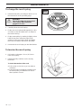
1. Open the collection bag. Insert the collection
bag tube from inside the bag to fit in the
vacuum inlet opening of the bag as illustrated in
the adjacent figure. Close the zipper on the bag.
2. Press the collection bag tube on the blower, turn
it 1/4 of a turn until a snap is heard. The section
of the tube that is covered by the collection bag
must arranged with its outlet pointing
downwards. Attach the carrying strap to the
harness ring.
3. Open the cover at the underside of the blower,
using a screw driver to disengage the locking
piece in the square opening.
4. Press the vacuum tube in the large opening at
the underside of the blower and turn it 45 degrees
until the bayonet mount locks.
5. Push the lower vacuum tube onto the upper tube
as shown in the adjacent figure.
6. Fit the auxiliary handle as described in the
separate instructions.
To vacuum debris from the
ground
The vacuuming device is an accessory and is not
included in the standard supply.
Fitting the collection bag with the
various vacuum tubes
WARNING!
When fitting the tubes to the
blower, the engine must be
switched off and the stop switch
must be in the stop position.
!
WARNING!
When working with the blower, wear
the required protecting equipment.
1. Hearing protection.
2. Eye protection.
3. Face mask in dusty
environments.
!
Vacuuming
Before vacuuming, put on the required safety equip-
ment.
25
23
22
24

English – 17
USING THE BLOWER
!
WARNING!
Do not operate the blower while
standing on a ladder or a stand.
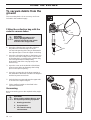
When operating the blower, the blower and
collection bag must be secured in the shoulder
strap. The strap should be worn over the shoulder
as shown in the adjacent figure.
WARNING!
Always check that the collection
bag is intact and the zipper is
closed before starting the blower.
Never use a damaged bag. There is
risk of injury due to flying debris.
Be careful, particurlarly if left hand
operation is applied. Avoid any
direct body contact with the
exhaust outlet area.
!
Start the blower as described on page 13. Work ac-
cording to the following instructions:
1. Do not vacuum large solid objects that can
damage the fan, such as wood, cans (tins) or
lengths of string or ribbon.
2. Do not let the vacuum tube strike the ground.
3. The bag can be emptied after having opened
the zipper on the side.
WARNING!
Never start the blower if the
inspection cover is not closed, is
damaged or cannot be closed.
(Exception: When the vacuum tube
is fitted).
!

18 – English
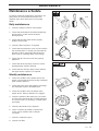
MAINTENANCE
The fuel quantity required in relation to the air flow,
provided by the opening in the throttle, is adjusted
by the L and H jets. If they are screwed clockwise,
the air/fuel mixture becomes leaner (less fuel) and if
they are screwed counterclockwise, the mixture
becomes richer (more fuel). A leaner mixture gives
rise to a higher engine speed and a richer mixture
gives rise to a lower engine speed.
The T screw regulates the idling speed. Turning the
T screw clockwise will increase the idling speed;
turning it counterclockwise will lower the idling
speed.
The carburetor has been carefully preset at the fac-
tory. However, additional adjustment may be required
due to climate, altitude, gasoline and type of two-
stroke engine oil used. The instructions below
describe how carburetor adjustment should be
carried out.
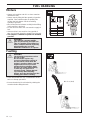
Function
Carburetor
The carburetor governs the engine speed via the
throttle. Air and fuel are mixed in the carburetor. The
air/fuel mixture is adjustable. To utilize the blower’s
maximum output, the settings must be correct.
The carburetor has three means of adjustment:
H = High speed jet
L = Low speed jet
T = Adjustment screw for idling
The carburetor is preset to the basic settings when
the blower is tested at the factory. These basic
settings are the following:
The H screw has been turned counterclockwise
to its end position against the stop.
The L screw has been turned counterclockwise
to its end position against the stop.
The recommended idling speed is 3000 rpm.
Basic (factory) settings
H L T
Adjustment
NOTE!
Do not remove the stops in the H and L
jets. If these stops are removed, the
blower will no longer satisfy the
environmental requirements established
by the California Air Resources Board.
Low speed jet, L
1. Check that the blower tube (15) and the nozzle
(14) are mounted on the blower.
2. Turn the H and L adjustment screws fully counter-
clockwise so that they rest against the stop.
3. Start the blower engine, see page 13, and
alternate letting it run at idling speed and at half
throttle for 1-2 minutes to warm up. If the engine
will not run at idling speed, turn the T screw
clockwise until it does.
4. Set the T screw to the setting, at which the engine
runs precisely at idling speed, but not faster.
5. Make a fine adjustment, turning the L screw so
that the engine will run at max. idling speed. Then
turn the L screw max 1/4 of a turn
counterclockwise.
6. Then turn the T screw to increase the engine
speed, if necessary.
NOTE!
When setting the H jet, the max.
permissible full-throttle interval is 10
seconds, after which the engine must run
at idling speed for at least 10 seconds.
High speed jet, H
1. Start the blower as described on page 13 and
alternate letting it run at idling speed and at half
throttle for 1-2 minutes to warm up.
2. Give the engine full throttle and adjust the H
screw until the engine runs at maximum speed.
3. Turn the H screw 1/8 of a turn counterclockwise
(less than 1/8 of a turn if the stop restricts this
adjustment).
Page is loading ...
Page is loading ...
Page is loading ...
Page is loading ...
Page is loading ...
Page is loading ...
Page is loading ...
Page is loading ...
Page is loading ...
Page is loading ...
Page is loading ...
Page is loading ...
-
 1
1
-
 2
2
-
 3
3
-
 4
4
-
 5
5
-
 6
6
-
 7
7
-
 8
8
-
 9
9
-
 10
10
-
 11
11
-
 12
12
-
 13
13
-
 14
14
-
 15
15
-
 16
16
-
 17
17
-
 18
18
-
 19
19
-
 20
20
-
 21
21
-
 22
22
-
 23
23
-
 24
24
-
 25
25
-
 26
26
-
 27
27
-
 28
28
-
 29
29
-
 30
30
-
 31
31
-
 32
32


Husqvarna 225 HBV User manual
- Category
- Air blowers/dryers
- Type
- User manual
Ask a question and I''ll find the answer in the document
Finding information in a document is now easier with AI
Related papers
-
Husqvarna 125B, 125BX-Series, 125BVX-Series User manual
-
Husqvarna 225B User manual
-
-
-
-
-
-
Husqvarna 356BT User manual
-
Husqvarna 150BT User manual
-