Page is loading ...

Manual # P80151157B - Date:2020/10/14
Failure to comply with these instructions could
result in a fire or explosion that could cause
serious bodily injury, death or property damage.
Whether this grill was assembled by you or
someone else, you must read this entire manual
before using your grill to ensure the grill is
properly assembled, installed and maintained.
Use your grill at least 3 feet away from any
wall or surface. Use your grill at least 3 feet
away from combustible objects that can melt or
catch fire such as vinyl or wood siding, fences
and overhangs or sources of ignition including
pilot lights on water heaters and live electrical
appliances.
THIS GAS APPLIANCE IS DESIGNED FOR
OUTDOOR USE ONLY.
Never use your gas grill in a garage, porch,
shed, breezeway or any other enclosed area.
Never obstruct the flow of ventilation air
around your gas grill housing.
Never disconnect the gas regulator or any gas
fitting while your grill is lit. A lit grill can ignite
leaking gas and cause a fire or explosion which
could result in property damage, personal injury
or death.
Ÿ
Ÿ
Ÿ
Ÿ
Ÿ
Ÿ
WARNING
! !
Ÿ
Grill Information Center:
Ÿ
Ÿ
NOTE TO ASSEMBLER / INSTALLER:
Leave this manual with the consumer.
NOTE TO CONSUMER:
Keep this manual for future reference.
RECORD YOUR SERIAL #
__________________
(see silver CSA label on main body of grill)
IMPORTANT:
Ÿ
FREE HELP
FROM THE GRILL EXPERTS
Barbeques Galore is the expert on this
product and trained to help you with:
visit www.grandhall.com or call:
1-800-474-5587
Monday - Friday 8:30am-4:30pm PST
Assembly Questions
Grill Operation
Replacement of Damaged or Missing parts
Ÿ
Ÿ
Ÿ
Liquid Propane Gas (LPG) Grill
Models B4019LP
Natural Gas (NG ) Grill
Models B4019NG
Operator's Manual

Table of Contents
Primary Safety Warnings............................1-3
Pre-Assembly Instructions...............................3
Part Diagrams and Lists............................4-8
Assembly Instructions.................................9-12
Use & Care Instructions:
• Gas Safety and Leak Tests..............13-17
• Natural Gas Connection............................18
• Lighting Instructions...............................19-20
• Troubleshooting...........................................21
• Rotisserie Instruction.............................22-24
Cleaning and Maintenance......................25-26
Cooking Guide..........................................A1-A5
Frequently Asked Questions...................A6-A7
Warranty...........................................Back Cover
2
Do not store or use gasoline or other
flammable liquids or vapors in the
vicinity of this or any other
appliances.
An LP cylinder not connected for
use shall not be stored in the vicinity
of this or any other appliance.
1.
2.
•
LPG models must be used with Liquid Propane
Gas and the regulator assembly supplied. Natural
Gas models must be used with Natural Gas only.
Any attempt to convert the grill from one fuel type
to another is extremely hazardous and will void the
warranty.
Keep gas regulator hose away from hot grill sur-
faces and dripping grease. Avoid unnecessary twist-
ing of hose. Visually inspect hose prior to each use
for cuts, cracks, excessive wear or other damage.
If the hose appears damaged do not use the gas
grill. Call 1-800-474-5587 for a certified replace-
ment hose.
California Proposition 65
Combustion byproducts produced when using this
product contain chemicals known to the State of Cali-
fornia to cause cancer, birth defects, or other reproduc-
tive harm.
Brass components on the grill, such as hose fittings,
propane cylinder valves (sold separately) and burner
valve stems, contain lead which is known to the State
of California to cause cancer, birth defects, or other
reproductive harm.
Never use charcoal or lighter fluid in this gas grill.
Failure to comply with these instructions could result
in a grease fire or explosion that could cause serious
bodily injury, death or property damage.
Before each use of your grill: Inspect the Grease Tray,
Grease Tray Heat Shield and inside of the Grill Bowl to
be sure there is no excessive grease and debris
buildup. Clean the Grease Tray, Grease Tray Heat
Shield and inside of the Grill Bowl frequently to elimi-
nate grease/debris build-up and to prevent grease
fires. Failure to comply with these instructions could
result in a grease fire and even a subsequent explo-
sion that could cause serious bodily injury, death or
property damage.
•
•
•
•
!
This appliance, when installed, must be electri-
cally grounded in accordance with local codes
or, in the absence of local codes, with the
National Electrical Code, ANSI/NFPA 70, or the
Canadian Electrical Code, CSA C22.1.
Keep any electrical supply cord and the fuel
supply hose away from any heated surfaces.
•
•
WARNING
!
DANGER
!
!
1.
2.
3.
4.
If you smell gas:
Shut off gas to the appliance.
Extinguish any open flame.
Open lid.
If odor continues, keep away from
the appliance and immediately call
your gas supplier or your fire
department.
WARNING
! !
WARNING
! !
Never cover or wrap the Cooking Grids, bottom
of the Grill Bowl, Grease Tray with aluminum foil
or any other material that will absorb grease.
! !
WARNING

Pre-Assembly Instructions For Your Safety
WARNING
CAUTION
! !
Failure to comply with these instructions may result
in a hazardous situation which, if not avoided, may
result in injury.
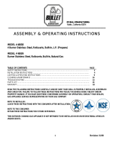
For safe operation ensure the Gas Valve Assem-
bly Orifice is inside the Burner Tube before using
your grill. (See figure). If the Orifice is not inside
the Burner Tube, lighting the Burner may cause
explosion and/or fire resulting in serious bodily
injury and/or property damage.
METHOD 1: Bend a stiff wire or wire coat hanger
into a small hook as shown and run the hook
through the Burner Tube and inside the Burner
several times to remove debris.
METHOD 2: Use a bottle brush with a flexible
handle and run the brush through the Burner
Tube and inside the Burner several times to
remove any debris.
METHOD 3: Use an air hose to force air through
each Burner Tube. The forced air should pass
debris or obstructions through the Burner and out
the Ports.
TO CLEAN BURNER TUBE,
INSERT HOOK
HERE
Burner Tube
9
3
Burner Port
Foot
1.
2.
3.
4.
Refer to the figure below and perform one of these
3 cleaning methods:
Carefully lift each Burner up and away from the Gas
Valve Orifice.
Check and clean Burner/Venturi Tubes for insects
and insect nests. A clogged tube can lead to a fire
beneath the grill.
Spiders and small insects can spin webs and nest
in the grill Burner Tubes during transit and ware-
housing which can lead to a gas flow obstruction
resulting in a fire in and around the Burner Tubes.
This type of "FLASHBACK FIRE" can cause serious
grill damage and create an unsafe operating con-
dition for the user.
To reduce the chance of FLASHBACK FIRE
you must clean the Burner Tubes as follows
before initial use. Also do this at least once a
month in summer and fall or whenever spiders are
active in your area, and if your grill has not been
used for an extended period of time.
Remove the screws from the rear of each Main Burner
using a Phillips Head Screwdriver or wrench.
WARNING: Grease can get very hot. Always handle the Grease
Tray with a flame retardant BBQ mitt. Before removing the
Tray, always be sure that the grill has properly cooled. Be
aware that the Tray does contain grease and be extremely
careful when removing the Tray to prevent spillage. Failure to
follow these instructions could cause serious bodily injury or
property damage.
Grill Installation Codes
The installation must conform with local codes or, in the
absence of local codes, with either the National Fuel Gas
Code, ANSI Z223.1/NFPA 54, Natural Gas and Propane
Installation Code, CSA B149.1, or Propane Storage and
Handling Code, B149.2.
•
•
•
PRE-ASSEMBLY
Read and perform the following pre-assembly instruc-
tions:
Tools Required for Assembly:
protective work gloves
protective eyewear
You will need assistance from another person to handle
the grill head and other large, heavy parts.
Open lid of shipping carton. Remove top sheet of
cardboard and packing materials. Lay cardboard sheet
on floor and use as a work surface to protect floor and
grill parts from scratches.
You may slice the carton front corners with a utility knife
to lay open the carton front panel. This allows you to
raise the Lid and remove the components packed inside,
making it easier to lift.
Use the Hardware and Part Diagrams to ensure all items
are included and free of damage.
Do not throw away the bags of hardware that are in-
cluded with boxed parts. These are required for assem-
bly.
Do not assemble or operate the grill if it appears
damaged. If there are damaged or missing parts when
you unpack the shipping box or you have questions dur-
ing the assembly process call 1-800-474-5587 M-F 8:30
AM-4:30PM PST for assistance.
CAUTION
!
When using electrical appliances, basic safety
precautions should always be used.
!
Orifice
Burner Tube
Gas Valve Assembly
Phillips Head Screwdriver

4
*One AA Battery included in the Hardware Pack
Hardware Diagram for Models B4019LP/NG
Hardware Parts List for Models B4019LP/NG
Pan Head Screw 3/16"x3/8"
Part # S182G03061
Qty. 7 (For LPG Model)
Qty. 2 (For NG Model)
PART # PART DESCRIPTION QTY PURPOSE OF PART
S182G03061Pan Head Screw 3/16" x 3/8" 2 Install the Transformer Bracket
S182G03061Pan Head Screw 3/16" x 3/8" 2 Install the Bracket with LP Regulator (LPG Model Only)
S182G03061Pan Head Screw 3/16" x 3/8" 3 Install the Tank Tray Set onto the Bottom Panel (LPG Model Only)
S313G0306BAA Battery 1

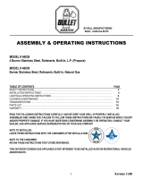
Parts Diagram for Model B4019LP/NG
5
Important: Use only Barbeques Galore’s replacement parts. The use of any part that is not a Barbeques Galore’s replacement
part can be dangerous and will also void your product warranty. Keep this Operator's Manual for convenient referral and
for part replacement.
For the repair or replacement parts you need:
Call 1-800-474-5587 M-F 8:30 AM - 4:30 PM PST
To obtain the correct replacement parts for your gas grill, please refer to the part numbers in this parts list. The
following information is required to ensure you receive the correct parts:
1. Model and Serial Number (see CSA label on grill)
2. Part Number
3. Part Description
4. Quantity of parts needed
1
2
3
4
5
6
7
15
16
8
9
11
10
28
33
A5
31
32B
29B
A4
30
A3
24
25
26
27
22
20
21
12
13
18
17A
19
23
A1
A2
14B
A6
A7
B1
B2
B4
B5
B6
32A
35
36
34
B3
14B
14A
37
29A
17B

Parts List for Model B4019LP/NG
KEY
DESCRIPTION
PART NO. QTY.
1 Lid Assembly
P0011982AA 1
2
Temperature Gauge Seat
P00614031A 1
3
Temperature Gauge
P00601551A 1
4 Lid Handle Bracket
P00303234B 2
5 Lid Handle Heat-Insulating Spacer
P06801002A 2
6 Lid Handle
P00205126B 1
7 Cooking Rack/Secondary
P01517009B 1
8 Cooking Grid
P01606047B 3
9 Smoker Box
P06701020A 1
10 Flame Tamer/Rack
P01720044B 1
11 Flame Tamer/Ceramic
P01804002A 8
12 Grill Bowl Assembly
P0073971BC 1
13 Protective Pad
P05518112K 4
14A Lid Hinge
P05501168A 2
14B Lid Spring
P05504117A 2
15 Burner Bracket
P02206314A 1
16 Burner/Main
P02001070B 4
17A Infrared Burner
P02005020A 2
17B Infrared Burner Electrode Cover
P06901031C 2
18 Grease Draining Tray Heat Shield
P06904069C 1
19 Grill Bowl Panel, Rear
P0071647BC 1
20 Gas Collector Box with Electrode
P02610020A 2
21 Infrared Burner Dual Electrode
P02625010A 1
22 Electric Wires Set - Electrode
P02615208A 1
23 Electric Ignitor, 6-Ports
P02505025G 1
24 Electric Ignitor Heat Shield
P06909011C 1
25 Electric Wires Set
P02627029A 1
26 Gas Valve/Manifold Assembly-NG
Y0060892 1
27 Grease Tray Slide Set
P05516149M 1
28 Grease Tray Assembly
Y0270033 1
29A Control Panel - Upper
P02916243S 1
29B Control Panel
P02916253S 1
30 Name Plate
P00407014C 1
6

7
Parts List for Model B4019LP/NG
KEY DESCRIPTION
PART NO. QTY.
31 Control Knob Seat P03447024A 7
32A Control Knob - Main Burner P03448014A 6
32B Control Knob - Back Burner P03448024A 1
33 Lighting Stick Assembly P05507140M 1
34 Regulator Assembly (NG) P03614005C 1
35 Regulator with Hose(LPG) - not included P03635005A 1
36 Regulator Hose Connector (LPG) - not included P03901056C 1
37 Tank Tray Set (LPG) - not included Y0340055 1
A3 Lamp Wires Set P05352030B 1
A4 Switch for Lamp P05360005B 1
A5 Electric Wires Set - LED Light P05383029B 1
A6 Lamp P05352028B 2
A7 Lamp Cover P05352013E 2
B1 Back Burner Assembly P02007077A 1
B2 Back Burner Orifice P06534048A 1
B3 Back Burner Hose P03701036A 1
B4 Back burner Thermocouple P05305072B 1
B5 Back Burner Electrode P02614074C 1
B6 Back Burner Thermocouple Protector P03328050C 1
Rotisserie Kit Y0250226 1
Operator's Manual P80151157B 1

Rotisserie Assembly Parts Diagram for B4019LP/NG
Rotisserie Assembly Parts List
Hardware for Rotisserie
Grill Information Center: If you have questions about assembly or grill operation, or if there are damaged
or missing parts when you unpack this unit from the shipping box, call us 8:00 am - 8 pm CST, Monday
through Friday at: 1-888-317-7642
8
Grill Information Center: If you have questions about assembly or grill operation, or if there are damaged or missing
parts when you unpack this unit from the shipping box, Call 1-800-474-5587 M-F 8:30 AM-4:30 PM PST
1
2
2
4
4
2
3
6
8
5
7
KEY
1.
2.
3.
4.
5.
6.
7.
8.
PART#
DESCRIPTION
QTY
1
3
1
2
1
1
2
2
Rot. Collar
Rot. Thumbscrew 1/4"x1/2"
Rot. Spit
Rot. Holding Fork
Rot. Motor Bracket
Rot. Motor/AC
Rot. Phillips Head Screw 3/16"x1/2" UNC
Rot. Washer 3/16"
P05508254A
S196G04081
P05508231A
P05508257A
P03308012C
P07101039B
S112G03081
S411G03061
Rotisserie Screw
3/16"x1/2" UNC
Qty. 2
Part # S112G03081
Rotisserie Washer
3/16"
Qty. 2
Part # S411G03061
Rotisserie Thumbscrew
1/4"x1/2"
Qty. 3
Part # S196G04081

9
Assembly Instructions for B4019LP&B4019NG
CAUTION : While it is possible for one person to assemble this grill, obtain assistance from another person
when handling some of the larger, heavier pieces.
Install the Transformer. Connect the Transformer to Power Source and Turn on the Lights.
2
Install the Transformer Mounting Bracket to the underside of the Left Panel of the Bowl Frame using
2 Phillips Head Screws 1/4"x1/4" and 2 Plain Washers 1/4" and tighten securely (see Fig. 1).
Attach the Transformer to the Transformer Mounting Bracket by inserting the two stud bolts on the transformer
bracket into the two key holes on the Mounting Bracket as shown. Press the Transformer downward until
it rests in place. (see Fig. 2 & Fig. 3).
Insert Transformer-Plug into Transformer-Socket and tighten securely. (see Fig. 4).
Depending on your island construction, you may need to make one hole on your Rear Island Panel. Make
sure the cord doesn't touch the ground. Connect the Transformer power supply cord plug into a properly
grounded 120VAC outlet.
Turn on the Grill Lights by pushing the Left Light Switch on the Control Panel.
Turn on the Control Knob Seat LED Lights by pushing the Right LED Switch on the Control Panel.
Fig. 4
Fig. 2
Fig. 3
1
Install Grill Head
With the help of your assistants, place the Grill Head into the cutout of your grill island (See Diagram).
NOTE: The grill head is designed to fit into an island of your own design. The island shown in
the diagram is for illustration purposes only. The diagram is not drawn to scale. An island is not
included with the purchase of this grill head.
Phillips Head Screw
3/16"x3/8"
Qty. 2
Part # S182G03061
Wire
Transformer-socket
Transformer-plug
AC-plug
Fig. 1
Note: The Transformer can
be attached to the top two
holes or the lower two holes.
For illustration purposes, the
Bowl is not shown.
Note: Make sure the
plug does not touch
the ground.
NOTE: The total of the ventilation openings must be a mini-
mum of 20 sq. inches.
For NG Model: The total of the UPPER ventilation openings
must be a minimum of 10 sq. inches.
For LPG Model: The total of the LOWER ventilation openings
must be a minimum of 10 sq. inches.
Upper and lower ventilation openings MUST BE PROVIDED
on both sides of built-in construction. The top of the upper
ventilations openings must be located within 5" from the
top of the island. The bottom of the lower ventilation open-
ings must be at least 1" or less from the floor of the island.
The top of the lower ventilation openings cannot be more
than 5" from the floor of the island. Every ventilation open-
ing must have a minimum of 1/8" wide.
Transformer
Transformer Mount-
ing Bracket

10
3
Install NG Regulator
Install the NG Regulator to the Manifold Extension Fitting and tighten securely.
Proper ventilation must be added to the island.
Pan Head Screw
3/16"x3/8"
Qty. 5
Part# S182G03061
Install Regulator, Tank Tray Set and Liquid Propane(LP) Gas Tank
4
5/8" UNF male
thread
stainless steel flexible connec-
tor (Not provided) must compy with the
Standard for connectors for Outdoor Gas
Appliances and Manufactured Homes,
ANSI Z21.75•CSA 6.27, and suitable for
outside installation.
The maximum length of the connection
shall be 6ft.(1.82m).
NOTE: To comply with the standarad, a built-in appliance for use with a remote self-contained LP
gas supply system must use rigid pipe,semi-rigid pipe or a connector complying with the Standard
for Connectors for Gas Appliances, ANSI Z21.24/CSA 6.10, or the Standard for Connectors for
Outdoor Gas Appliances and Manufactured Homes, ANSI Z21.75/CSA 6.27 to connect the appliance
to the remote self-contained gas supply system. For safety consideration, we suggest to use a
stainless steel flexible connector as shown. But, if using semi-rigid tubing, do not use materials
made of aluminum or aluminum alloy tubing. The connector should be installed at the location
visible when opening the door.
On the proper location, drill 2 holes on the island left side panel for installing the regulator bracket. Then
install the regulator using 2 Pan Head Screws 3/16"x3/8" and tighten securely.
On the proper location, drill 3 holes on the island left bottom panel for installing the tank tray set. Then
install tank tray set using 3 Pan Head Screws 3/16"x3/8" and tighten securely.
Connect the stainless steel flexible connector to the manifold and regulator, then use a clamp to hold
the stainless steel flexible connector as shown for securing.
Place the LP gas tank into the tank tray set. Make sure the tank valve facing the right rear corner of
left island. Tighten the wing bolt to secure the LP gas tank. (See Fig.3)
Connect the LP regulator onto the LP gas tank.
CAUTION: There shall be a minimum clearance of 2 inches (50.8 mm) between the floor of the LP-gas cylinder
enclosure and the ground. Proper ventilation must be added to the island.
Manifold Extension Fitting
NG Regulator
Fig. 3
Island Bottom
Panel
Tank Tray Set

11
5
Install Partition Panel
Ignitor Cap
Ignitor Slot
AA Battery
Spring
Install Ignitor Battery
Remove Ignitor Cap from Control Panel.
Place supplied AA battery into the Ignitor Slot with positive pole facing you.
Position the Cap and Spring over the AA battery and tighten onto Control Panel.
6
Partition Panel
(above the Gas Tank)
Fig. 4
Tank Tray Set
5"
22-24"
21"
1"
17-19"
5"
Vent Openings
must be at least
1/8" wide
Install the Partition Panel (not included in this unit) onto the left island.
Make sure there is 22-24" of clearance between the partition panel and the Tank
Holder Assembly.
CAUTION: Build your grill island before installing the LP Gas Tank and Partition Panel (Not included
in this unit). Refer to the heights listed in Fig. 4 for constructing your grill island. An island unit is
not included with the purchase of your Grill Head.

12
Final Grill Assembly Step
When you have finished assembling your grill,
be sure that all screws are tightened for safe
operation of your grill.
Before each use of the grill, make sure the
Grease Tray is fully seated under the Grill Bowl.
CAUTION: Before each use of your grill, inspect
the Grease Tray, Grease Tray Heat Shield and in-
side of the Grill Bowl to be sure there is no exces-
sive grease and debris buildup. Clean the Grease
Tray, Grease Tray Heat Shield and inside of the
Grill Bowl frequently to eliminate grease/debris
build-up and to prevent grease fires.
Cooking Rack/Secondary
Cooking Grids
Spark Electrode Tip
Spark Receiver
Spark Gap 3/16"
Gas Collector
Box
AA Battery may be installed backwards.
Electric wires may be loose. Remove the AA
Battery and inspect the Ignitor Junction Box
found behind the Control Panel and recon-
nect any loose wires.
-
-
Main Burner Electrode Check
With the assistance of another person,
perform this Electrode Check before
proceeding.
7
Be sure all Control Knobs are set to "OFF" and
open the Grill Lid.
Have your assistant stand to the right of the
grill and look toward the front of the grill bowl.
Never put your face inside the Grill Head.
Push and turn Burner Control Knob to HI/ and
you will hear a "clicking" sound as the burner
is being ignited. Your assistant should see a
blue spark within each Gas Collector Box. If
a spark is present the Electrode Tips are
properly positioned.
If no spark is seen, the Spark Gap needs to
be adjusted as follows:
This test will ensure that the Spark Electrode
Tips are properly positioned so your grill lights
easily.
•
•
If the gap between the Spark Electrode Tip
and Receiver is more than 3/16" wide use
needle nose pliers to gently squeeze the
Gas Collector Box to narrow gap.
Recheck the Electrode again, if no "clicking"
sound is heard:
Infrared Burner and Rotisserie Burner
Electrode Check
8
Push and turn Infrared Burner Control Knob &
Rotisserie Burner Control Knob to HI/ . Look
for spark between electrode tip and spark
receiver tip.
If you don't see a spark from the Infrared
Burner Electrode or Rotisserie Burner, adjust
the gap between the electrode tip and spark
receiver tip to 3/16" wide.
Install Cooking Components
9
Place the Flame Tamer Rack inside the Grill
Bowl. Position it onto the lower ledge of the
Bowl above the burners. Next, place the Flame
Tamers on the Flame Tamer Rack. Make sure
the flame tamer side with the wider holes is
placed downwards. (See the diagrams on
right)
Place the Cooking Grids on the ledge above
the Flame Tamers.
Place the Secondary Cooking Rack into the
slots on Grill Bowl Side Panels.
Flame tamer
Flame tamer Rack

Installation Instruction
Combustible Clearance
Island Contstruction
Liquid Propane(LP) Ventilation
Island / Grill Placement
It is required that the
interior of the island/
structure to be built
hollow and with proper
ventilation based on gas
type(see below images
for ventilation). Being
hollow allows the proper
air flow for the BBQ
Unit to both breath and
fuction properly, and
vent correctly(based on
the ga s type).
Natural Gas (NG) Ventilation
36"
36"
36"
36"
BBQ Grills are
required to be 36”
away from any
combustible
material in all
directions. Failure
to do so could
lead to the damage of
the island/structure, the
surrounding components and
area, and the BBQ grill itself.
NOTE: Island/structure should not be built
out of any type of combustible material.
Ventilation is
required to be
along the bottom
of the island/
structure for LP
units due to LP
Gas weighs more
than air. This will
ensure proper gas
ventilation in the case of a gas
leak. This will also allow for proper
air flow of LP units.
NOTE: Access doors are not considered
proper ventilation.
Ventilation is
required to be
along the top of
the island/
structure for NG
units due to NG
Gas weighs less
than air. This will
ensure proper gas
ventilation in the case of a gas
leak. This will also allow for proper
air flow of NG units.
NOTE: Access doors are not considered
proper ventilation.
It is suggested
that when designing
and placing
the BBQ Grill,
island/ structure
that it is
placed/built facing
the wind (if the
island/structure is located
in a high wind area).
If this is an unavoidable situation it is
suggested to build a backsplash on the island/
structure to help divert/prevent wind from
entering the rear of the BBQ unit.
Note: these guidelines will be considered if there is
any warranty request submitted by the
customer. Not following these guidelines can result
in the grill not functioning correctly and can lead to
voiding the warranty on specific parts based on the
issue that arises.
Grand Home Holdings / Barbeques Galore are not
liable for any 3rd party construction or installation of
its products. Grand Home Holdings / Barbeques
Galore can decline “service” and or “warranty” of
parts for the product if the above installation/
construction guidelines are not followed. Grand
Home Holdings / Barbeques Galore may request
photos of the installation/construction if a warranty
claim is placed to verify proper installation of the
product.
! !
WARNING
13

14
USE AND CARE INSTRUCTIONS
CORRECT USE OF LP GAS TANK
The LP Gas tank must be constructed and marked in
accordance with the Specifications for LP-Gas Cylinders
of the U.S. Department of Transportation (D.O.T.) or the
National Standard of Canada, CAN/CSA-B339, Cylinders,
Spheres and Tubes for Transportation of Dangerous
Goods, and Commission; as applicable.
The LP Gas tank must have a shutoff valve, terminating
in an LP Gas supply tank valve outlet, that is compatible
with a Type 1 tank connection device. The LP Gas tank
must also have a safety relief device that has a direct
connection with the vapor space of the tank.
The tank supply system must be arranged for vapor
withdrawal.
The LP Gas tank must have a collar to protect the tank
valve.
Never connect an unregulated LP gas tank to your gas
grill. The gas regulator assembly supplied with your gas
grill is adjusted to have an outlet pressure of 11" water
column (W.C.) for connection to an LP gas tank. Only
use the regulator and hose assembly supplied with your
gas grill. Replacement hose and regulator assembly
must be identical to those listed in the parts list of this
Operator's Manual as specified by Barbeques Galores..
Have your LP Gas dealer check the release valve after
every filling to ensure it remains free of defects.
Always keep LP Gas tank in upright position.
Do not subject the LP Gas tank to excessive heat.
Never store an LP Gas tank indoors. If you store your
gas grill in the garage always disconnect the LP Gas
tank first and store it safely outside.
LP Gas tanks must be stored outdoors in a well-
ventilated area and out of the reach of children.
Disconnected LP Gas tanks must not be stored in a
building, garage or any other enclosed area.
The regulator and hose assembly can be seen by
opening the cart or island doors. They must be inspected
before each use of the grill. If the hose is damaged in
any way, it must be replaced prior to using the grill again.
Any attempt to convert the grill from one fuel type to
another is extremely hazardous and will void the war-
ranty.
Never light your gas grill with the lid closed or before
checking to ensure the burner tubes are fully seated over
the gas valve orifices.
Never allow children to operate your grill. Do not allow
children or pets to play near your grill. Always supervise
children and pets if they are in the vicinity of the unit.
!
WARNING
!
Keep fire extinguisher readily accessible. In the
event of a oil/grease fire, do not attempt to extinguish
with water. Use type B extinguisher or smother with
dirt, sand or baking soda.
In the event of rain, turn off the burners and gas
supply. Wait for the grill to cool, and then place a
cover on it.
Use your grill on a level, stable surface in an area
clear of combustible materials.
LP Gas grill models are designed for use with a standard
20 lb. Liquid Propane Gas (LP Gas) tank (sold sepa-
rately). Never connect your gas grill to an LP Gas tank
that exceeds this capacity. A tank of approximately 12
inches in diameter by 18-1/2 inches high is the maximum
size LP Gas tank to use. You must use an "OPD" gas
tank which has a listed Overfill Prevention Device. This
safety feature prevents tank from being overfilled which
can cause a malfunction of the LP Gas tank.
Do not leave grill unattended when in use.
Do not move the appliance when in use.
Allow the grill to cool before moving or storing.
Do not use your grill as a heater.
•
•
•
•
Use your grill at least 3 feet away from any wall or
surface.
Use your grill 3 feet away from any combustible
objects that can melt or catch fire such as vinyl or
wood siding, fences, overhangs (See Diagram Be-
low), or any other sources of ignition; including pilot
lights and live electrical appliances.
Do not use your grill under any overhead combus-
tible construction.
Never use your gas grill in a garage, porch, shed,
breezeway, or any other enclosed area.
Never use your gas grill on a balcony, deck, or patio
above the ground floor of your home.
•
!
Do not store a spare LP-Gas tank under or near this
appliance.
Never fill the tank beyond 80 percent full; and
If the information in "(a)" and "(b)" is not followed
exactly, a fire causing death or serious injury may
occur.
A.
B.
C.
WARNING
!
Use of alcohol, prescription or non-prescription drugs
can impair your ability to properly assemble and safely
operate your grill.
Never use charcoal or lighter fluid in this grill.
This grill is not intended to be installed in or on
recreational vehicles and/or boats.
The grill is not intended for commercial use.

15
USE AND CARE INSTRUCTIONS
!
WARNING
!
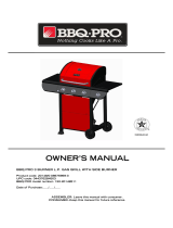
Refer to the this table when designing the island unit
for the B3812BLP/NG & BAI12BLP/NG. Side* and
Rear* show the minimum amount of distance the unit
must be from combustibles (ex. Vinyl or wood siding,
fences and overhangs) or sources of ignition (ex. Pilot
lights on water heaters and live electrical appliances).
Height* shows the minimum height the island unit
must be starting from the ground up. Proper ventilation
is required for all gas types.
Brush soapy solution onto LP Gas tank in the ar-
eas indicated by the arrows. See diagram.
If growing bubbles appear do not use or move the
LP Gas tank. Call an LP Gas Supplier or your Fire
Department.
NOTE about LP Gas Tank Exchange Programs
Many retailers that sell grills offer you the option of
replacing your empty LP Gas tank through an exchange
service. Use only those reputable exchange compa-
nies that inspect, precision fill, test and certify their
tanks. Exchange your tank only for an OPD safety fea-
ture-equipped tank as described in the LP Gas tank
section of this guide.
How to Leak Test your LP Gas Tank
Use a clean paintbrush and a 50/50 mild soap and
water solution.
For your safety:
Leak test new and exchanged LP Gas tanks BEFORE
connecting one to your grill.
Always keep new and exchanged LP Gas tanks in an
upright position during use, transit or storage.
All leak tests must be repeated each time your LP
Gas tank is exchanged or refilled.
When checking for gas leaks do not smoke.
Do not use an open flame to check for gas leaks.
Your grill must be leak tested outdoors in a well-ven-
tilated area, away from ignition sources such as gas
fired or electrical appliances. During the leak test, keep
your grill away from open flames or sparks.
Do not use household cleaning agents. Damage to
gas assembly components can result.
Ÿ
Ÿ
Ÿ
If growing bubbles appear do not use or move the
LP Gas tank. Contact an LP Gas Supplier or your
fire department!
WARNING
!
!
Side*
Depth
Height
Width
Non-combustible
Construction
Rear*
6" minimum
clearance from
cutout (for lid)
Height*
Model Height Width Depth Side* Rear*Height*
B4019B
LP/NG
10" 38-1/2" 23 36" 36" 29"

USE AND CARE INSTRUCTIONS
16
Secure a 20lb LP Gas Tank to Gas Grill
Note: You can only use a 20lb LP Gas Tank in this
Gas Grill.
NOTE: When using Propane, EXTREME CAUTION
should be used to provide ample ventilation of vapor
from the enclosure. LP Gas vapor is heavier than air
and SERIOUS INJURY from a DANGEROUS EXPLO-
SION could occur if LP Gas is allowed to accumulate
in an enclosure and then ignited. Both the Barbecue
enclosure and LP cylinder enclosure require venting
that must be provided at the floor level of the enclo-
sure to allow any leaking LP Gas vapor to escape
(see Fig. 1).
NOTE: When installing a barbecue equipped for liquid
propane in an island, the propane tank must be in
a separate enclosure that is completely isolated from
the barbecue. It must be cross-ventilated in accor-
dance with the current standards. The propane tank
MUST NEVER be installed directly under the barbe-
cue.
NOTE: The total of the upper ventilation openings
must be a minimum of 20 sq. inches. The total of
the lower ventilation openings must be a minimum
of 10 sq. inches. Upper and lower ventilation open-
ings MUST BE PROVIDED on both sides of built-in
construction. The top of the upper ventilations open-
ings must be located within 5" from the top of the
island. The bottom of the lower ventilation openings
must be at least 1" or less from the floor of the island.
The top of the lower ventilation openings cannot be
more than 5" from the floor of the island. Every
ventilation opening must have a minimum of 1/8" (See
Fig. 4 on page 22). Contact a Barbeques Galore’s
associate for more details.
Fig. 1
Stainless Steel Tube (Refer
to the Note below).
5/8" UNF
Thread
The built-in appliance for use with a remote self-contained LP
Gas supply system must use rigid pipe, semi-rigid tubing or a
connector complying with the Standard for Connections for
Gas Appliances, ANSI Z21.24/CSA6.10, or the standard for
Connectors Outdoor Gas Appliance and Manufactured
Homes, ANSI21.75/CSA 6.27 and suitable for outside installa-
tion. The maximum length of the connection shall be 6 ft(1.
82m).
The connector should be installed at the location visible
when opening the door.
The connector must be away from any sharp points or sharp
edges.
When using semi-rigid tubing, do not use materials made of
aluminium or aluminium alloy.
Note:
Air Vents
Partition Panel
Non-Combustible
Construction, such as
stone, marble, cement

17
WARNING
!
LP Gas Model only:
Connect Regulator with Hose to your LP Gas Tank
Turn all Control Knobs to the OFF position.
Inspect the valve connection port and regulator
assembly for damage or debris. Remove any de-
bris. Never use damaged equipment.
Connect the regulator assembly to the tank valve
and HAND TIGHTEN nut clockwise to a full stop. DO
NOT use a wrench to tighten because it could
damage the Quick Coupling Nut and result in a gas
leak/fire hazard.
Open the tank valve 1/4 to 1/2 of a full turn
(counterclockwise) and use a soapy water solution
to check all connections for leaks before attempt-
ing to light your grill. See "Check All Connections
for LP Gas Leaks." If a leak is found, turn the tank
valve off and do not use your grill until the leak is
repaired.
USE AND CARE INSTRUCTIONS
1.
WARNING
! !
Do not store spare LP cylinder within
10 feet (3m) of this appliance.
Do not store or use gasoline or other
flammable liquids and vapors within 25
feet (8m) of this appliance.
When cooking with oil/grease, do not
allow the oil/grease to get hotter 350°F
(177°C).
Do not leave oil/grease unattended.4.
2.
3.
Check all connections for LP Gas Leaks
Never test for leaks with an open flame. Prior to first
use, at the beginning of each season, or every time
your LP Gas tank is changed, you must check for gas
leaks. Follow these three steps:
Make a soap solution by mixing one part liquid
detergent and one part water.
Turn the grill Control Knobs to the full OFF position,
then turn the gas ON at source.
Apply the soap solution to all gas connections
indicated by the arrows. (See diagram). If bubbles
appear in the soap solution the connections are
not properly sealed. Check each fitting and tighten
or repair as necessary.
Type 1 connection per ANSI
Z21.58b-2012/CSA 1.6b-2012
Quick
Coupling Nut
CAUTION: When the appliance is not in use the gas must
be turned off at the tank. Place dust cap on cylinder valve
outlet whenever the cylinder is not in use. Only install the
type of dust cap on the cylinder valve outlet that is provided
with the cylinder valve. Other types of caps or plugs may
result in leakage of propane.
If you have a gas leak that cannot be repaired,
turn off the gas at the source and disconnect the
fuel line from your grill. Call 1-800-474-5587 or your
gas supplier for repair assistance.
!
Disconnecting A Liquid Propane Gas (LPG)
Tank From Your Grill
Make sure the Burner Valves and LP Gas tank valve
are off. (Turn clockwise to close.)
Detach the hose and regulator assembly from the
LP Gas tank valve by turning the Quick Coupling
Nut counterclockwise. Do not use a wrench or any
tools when turning the Quick Coupling Nut.
(for B4019BLP Model)
WARNING
!
Failure to read and follow the Use and Care
Instructions could result in a fire or explosion
that could cause serious bodily injury, death, or
property damage.
!
LP Gas Tank
Gas Valve/Manifold
Assembly
Regulator
with Hose (LPG)
Stainless Steel Tube
(not included in this kit)

18
Natural Gas Connection
Natural Gas Model only:
Connecting Natural Gas To Your Grill
Check all connections for Natural Gas Leaks
Never test for leaks with an open flame. Prior to first use
and at the beginning of each season, you must check
for gas leaks. Follow these three steps:
Make a soap solution by mixing one part liquid
detergent and one part water.
Turn the grill Control Knobs to their full OFF
positions. Next, turn the gas ON at the source.
Apply the soap solution to all gas connections
indicated by the arrows. See Fig.3. If bubbles
appear in the soap solution the connections are
not properly sealed. Check each fitting and tighten
or repair as necessary.
Fig.2
Gas Supply
Inside Wall
Outside Wall
Male Fitting
To Grill
Locking
Shut Off
Shut Off
Quick
Disconnect
Your natural gas grill is designed for use with
natural gas (NG) only. The gas pressure Regu-
lator supplied with this appliance must be in-
stalled and used on your grill. The unit and
Regulator are set to operate with an outlet
pressure of 4" W.C.
Install a Shutoff Valve at the gas supply source
outdoors at a point after the gas pipe exits the
outside wall and before the quick-disconnect hose.
Or install it at the point before the gas line piping
enters the ground. See Fig. 2.
Pipe sealing compound or pipe thread tape resis-
tant to the action of natural gas must be used on all
male pipe thread connections.
Disconnect your gas grill from fuel source when the
gas supply is being tested at high pressures. This
gas grill and its individual shutoff valve must be
disconnected from the gas supply pipe system
during any pressure testing of that system at pres-
sure in excess of 1/2 psi (3.5kpa).
Turn off your gas grill when the gas supply is being
tested at low pressures. The grill must be isolated
from the gas supply pipe system by closing its
individual manual shutoff valve during any pres-
sure testing of the gas supply pipe system at
pressures equal to or less than 1/2 psi (3.5kpa).
Natural Gas Safety Instructions
Connect the Swivel nut of the 12' Natural Gas
Hose to the horizontal fitting of NG Regulator
as shown in Fig.1. Connect the other hose end
(male plug) to the gas supply line from your
home. Read and follow the "Natural Gas Safety
Instructions" below.
Fig.3
Fig.1
NG Regulator
Swivel Nut
If the length of line required does not exceed 50
feet, use a 5/8" O.D tube. One size larger should
be used for lengths greater than 50 feet.
Gas piping must be copper tubing, type K or L;
polyethylene plastic tube, with a minimum wall
thickness of 0.62 inch; or standard weight (sched-
ule 40) steel or wrought iron pipe.
Copper tubing must be tin-lined if the gas con-
tains more than 0.3 grams of hydrogen sulfide per
100 cubic feet of gas.
Plastic tubing is suitable only for outdoor, under-
ground use.
Gas piping in contact with earth, or any other
material which may corrode the piping, must be
protected against corrosion in an approved man-
ner.
Underground piping must have a minimum of 18'
cover.
Gas Line Piping:
Gas Valve / Mani-
fold Assembly
NG Regulator
(for B4019ANG Models)

USE AND CARE INSTRUCTIONS
19
5.
8.
7.
9.
6.
Set Control Knobs to OFF and open the LP Gas tank valve
SLOWLY 1/4 of a turn. For Natural Gas open the Shut Off
Valve at source.
Push and turn Right Main Burner Control Knob to Ingitor/HI.
You will hear a clicking sound as the burner is being ignited.
Always light the RIGHT Main Burner first.
If ignition does not occur in 5 seconds, turn the Burner
Control(s) off, wait 5 minutes, and repeat the lighting
procedure. If ignition still does not occur, turn the burner
control(s) and gas source OFF. Wait 5 minutes for gas to
clear and then conduct a leak test of ALL gas connections
and gas sources as explained in the Use and Care section
of this manual. If no leaks are detected, wait 5 minutes for
any gas to clear and repeat the lighting procedure.
After one Burner is lit, turn the tank valve SLOWLY one
more 1/4 of a turn.
Turn each other burner knob to Ingitor/HI to light. Note:
When lighting all main burners, start with the burner fur-
thest from fuel source location, then light remaining burn-
ers in sequence moving toward fuel source.
Failure to replace a faulty hose, secure gas supply
connections or to open the Lid before proceeding to
the Lighting Procedures could result in a fire or
explosion that could cause serious bodily injury,
death, or property damage.
WARNING
!
!
Grill Lighting Instructions
1.
Main Burner
Rotisserie
Burner
Infrared
Burner
Open LP Gas tank
OFF
Ingitor/HI
LO
Rotisserie Burner Lighting Instructions
Follow steps 1 through 5 of the Grill Lighting Instruc-
tions.
Push and turn Control Knob to Ingitor/HI and hold
knob in.
Keep pressing and hold in 5 - 10 seconds before
releasing.
If ignition does not occur in 5 seconds, turn the Burner
Control(s) off, wait 5 minutes, and repeat the lighting
procedure. If ignition still does not occur, turn the
burner control(s) and gas source OFF. Wait 5 minutes
for gas to clear and then conduct a leak test of ALL gas
connections and gas sources as explained in the Use
and Care section of this manual. If no leaks are
detected, wait 5 minutes for any gas to clear and
repeat the lighting procedure.
After Burner is lit, turn the tank valve SLOWLY one more
1/4 of a turn.
IMPORTANT: Do not use the Rotisserie Burner and Main
Burners at the same time. Rotisserie burner is for Rotis-
serie Cooking only.
1.
2.
4.
3.
5.
Before each use, check all hoses for cracks, nicks, cuts,
burns or abrasions. If a hose is damaged in any way, do
not use your grill before replacing the hose with an
authorized part from the Parts List. Also make sure all
gas supply connections are securely tightened.
Familiarize yourself with all Safety and Use and Care
instructions in this manual. Do not smoke while
lighting your grill or when checking the gas supply
connections.
Be sure that the LP Gas tank is filled, and lock
Casters (if the grill is a cart model) to prevent
movement during grill operation.
Open the Grill Lid.
4.
3.
2.
OFF
LO
Ingitor/HI
OFF
Ingitor/HI

Infrared Burner Lighting Instructions
Follow steps 1 through 5 of the Grill Lighting
Instructions.
Push and turn Control Knob to Ingitor/HI. You will hear
a clicking sound as the burner is being ignited.
If ignition does not occur in 5 seconds, turn the Burner
Control(s) off, wait 5 minutes, and repeat the lighting
procedure. If ignition still does not occur, turn the
burner control(s) and gas source OFF. Wait 5 minutes
for gas to clear and then conduct a leak test of ALL gas
connections and gas sources as explained in the
Use and Care section of this manual. If no leaks are
detected, wait 5 minutes for any gas to clear and
repeat the lighting procedure.
After Burner is lit, turn the tank valve SLOWLY one
more 1/4 of a turn.
1.
4.
3.
2.
Manually Lighting Your Grill By Paper Match
20
To light your gas grill by match, insert a match into the
Lighting Stick and follow steps 1 through 5 of the Grill
Lighting Instructions to light the infrared burners. Then,
light the match and place Lighting Stick through the
Cooking Grids on the grill to light the main burners. Turn
the correlated Control Knob to the Ingitor/HI setting to
release gas. The Burner should light immediately.
OFF
LO
Ingitor/HI
/