Supermicro SUPERSERVER 6015X-3 User manual
- Category
- Server barebones
- Type
- User manual
This manual is also suitable for

SUPERSERVER 6015X-3
SUPERSERVER 6015X-T
S
UPERSERVER 6015X-8
USER’S MANUAL
1.0a
SUPER
®

Unless you request and receive written permission from SUPER MICRO COMPUTER, you may not
copy any part of this document.
Information in this document is subject to change without notice. Other products and companies
referred to herein are trademarks or registered trademarks of their respective companies or mark
holders.
Copyright © 2007 by SUPER MICRO COMPUTER INC.
All rights reserved.
Printed in the United States of America
Manual Revision 1.0a
Release Date: April 23, 2007
The information in this User’s Manual has been carefully reviewed and is believed to be accurate.
The vendor assumes no responsibility for any inaccuracies that may be contained in this document,
makes no commitment to update or to keep current the information in this manual, or to notify any
person or organization of the updates. Please Note: For the most up-to-date version of this
manual, please see our web site at www.supermicro.com.
SUPERMICRO COMPUTER reserves the right to make changes to the product described in this
manual at any time and without notice. This product, including software, if any, and documenta-
tion may not, in whole or in part, be copied, photocopied, reproduced, translated or reduced to any
medium or machine without prior written consent.
IN NO EVENT WILL SUPERMICRO COMPUTER BE LIABLE FOR DIRECT, INDIRECT, SPECIAL,
INCIDENTAL, SPECULATIVE OR CONSEQUENTIAL DAMAGES ARISING FROM THE USE
OR INABILITY TO USE THIS PRODUCT OR DOCUMENTATION, EVEN IF ADVISED OF THE
POSSIBILITY OF SUCH DAMAGES. IN PARTICULAR, THE VENDOR SHALL NOT HAVE
LIABILITY FOR ANY HARDWARE, SOFTWARE, OR DATA STORED OR USED WITH THE
PRODUCT, INCLUDING THE COSTS OF REPAIRING, REPLACING, INTEGRATING, INSTALLING
OR RECOVERING SUCH HARDWARE, SOFTWARE, OR DATA.
Any disputes arising between manufacturer and customer shall be governed by the laws of Santa
Clara County in the State of California, USA. The State of California, County of Santa Clara shall
be the exclusive venue for the resolution of any such disputes. Supermicro's total liability for
all claims will not exceed the price paid for the hardware product.
FCC Statement: This equipment has been tested and found to comply with the limits for a Class
A digital device pursuant to Part 15 of the FCC Rules. These limits are designed to provide
reasonable protection against harmful interference when the equipment is operated in a commercial
environment. This equipment generates, uses, and can radiate radio frequency energy and, if not
installed and used in accordance with the manufacturer’s instruction manual, may cause harmful
interference with radio communications. Operation of this equipment in a residential area is likely
to cause harmful interference, in which case you will be required to correct the interference at your
own expense.

iii
Preface
Preface
About This Manual
This manual is written for professional system integrators and PC technicians. It
provides information for the installation and use of the 6015X-3/6015X-T/6015X-
8. Installation and maintenance should be performed by experienced technicians
only.
The 6015X-3/6015X-T/6015X-8 is a high-end server based on the SC819TQ-700/
SC819S-700 1U rackmount chassis and the X7DBX-i/X7DBX-8, a dual processor
serverboard that supports Intel
®
Xeon
TM
LGA 771 processors and up to 32 GB of
FBD ECC DDR2-667/533 SDRAM.
Manual Organization
Chapter 1: Introduction
The fi rst chapter provides a checklist of the main components included with
the server system and describes the main features of the X7DBX-i/X7DBX-8
serverboard and the SC819TQ-700/SC819S-700 chassis, which comprise the
6015X-3/6015X-T/6015X-8.
Chapter 2: Server Installation
This chapter describes the steps necessary to install the 6015X-3/6015X-T/6015X-8
into a rack and check out the server confi guration prior to powering up the system.
If your server was ordered without processor and memory components, this chapter
will refer you to the appropriate sections of the manual for their installation.
Chapter 3: System Interface
Refer here for details on the system interface, which includes the functions and
information provided by the control panel on the chassis as well as other LEDs
located throughout the system.

iv
Chapter 4: System Safety
You should thoroughly familiarize yourself with this chapter for a general overview
of safety precautions that should be followed when installing and servicing the
6015X-3/6015X-T/6015X-8.
Chapter 5: Advanced Serverboard Setup
Chapter 5 provides detailed information on the X7DBX-i/X7DBX-8 serverboard,
including the locations and functions of connections, headers and jumpers. Refer
to this chapter when adding or removing processors or main memory and when
reconfi guring the serverboard.
Chapter 6: Advanced Chassis Setup
Refer to Chapter 6 for detailed information on the SC819TQ-700/SC819S-700
server chassis. You should follow the procedures given in this chapter when in-
stalling, removing or reconfi guring SAS/SATA/SCSI or peripheral drives and when
replacing system power supply modules and cooling fans.
Chapter 7: BIOS
The BIOS chapter includes an introduction to BIOS and provides detailed informa-
tion on running the CMOS Setup Utility.
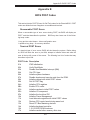
Appendix A: BIOS POST Messages
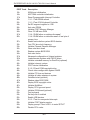
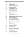
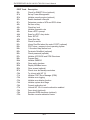
Appendix B: BIOS POST Codes
Appendix C: Software Installation
Appendix D: System Specifi cations
S
UPERSERVER 6015X-3/6015X-T/6015X-8 User's Manual

v
Preface
Notes

vi
Table of Contents
Preface
About This Manual ...................................................................................................... iii
Manual Organization ................................................................................................... iii
Chapter 1: Introduction
1-1 Overview ......................................................................................................... 1-1
1-2 Serverboard Features ..................................................................................... 1-2
1-3 Server Chassis Features ................................................................................ 1-3
1-4 Contacting Supermicro ................................................................................... 1-6
Chapter 2: Server Installation
2-1 Overview ......................................................................................................... 2-1
2-2 Unpacking the System ................................................................................... 2-1
2-3 Preparing for Setup ........................................................................................ 2-1
Choosing a Setup Location ...................................................................... 2-2
Rack Precautions ..................................................................................... 2-2
Server Precautions ................................................................................... 2-2
Rack Mounting Considerations ................................................................ 2-3
2-4 Installing the System into a Rack ................................................................... 2-4
2-5 Checking the Serverboard Setup ................................................................... 2-8
2-6 Checking the Drive Bay Setup ..................................................................... 2-10
Chapter 3: System Interface
3-1 Overview ......................................................................................................... 3-1
3-2 Control Panel Buttons .................................................................................... 3-1
UID ........................................................................................................... 3-1
Power ....................................................................................................... 3-1
3-3 Control Panel LEDs ........................................................................................ 3-2
UID ........................................................................................................... 3-2
Overheat/Fan Fail .................................................................................... 3-2
NIC2 ......................................................................................................... 3-2
NIC1 ......................................................................................................... 3-2
HDD .......................................................................................................... 3-3
Power ....................................................................................................... 3-3
3-4 Drive Carrier LEDs ......................................................................................... 3-3
SUPERSERVER 6015X-3/6015X-T/6015X-8 User's Manual

Chapter 4: System Safety
4-1 Electrical Safety Precautions .......................................................................... 4-1
4-2 General Safety Precautions ........................................................................... 4-2
4-3 ESD Precautions ............................................................................................ 4-3
4-4 Operating Precautions .................................................................................... 4-4
Chapter 5: Advanced Serverboard Setup
5-1 Handling the Serverboard .............................................................................. 5-1
5-2 Processor and Heatsink Installation ............................................................... 5-2
5-3 Connecting Cables ......................................................................................... 5-5
Connecting Data Cables .......................................................................... 5-5
Connecting Power Cables ....................................................................... 5-5
Connecting the Control Panel .................................................................. 5-6
5-4 I/O Ports ......................................................................................................... 5-7
5-5 Installing Memory ........................................................................................... 5-7
5-6 Adding PCI Cards ........................................................................................... 5-9
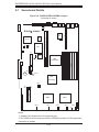
5-7 Serverboard Details ...................................................................................... 5-10
X7DBX-i/X7DBX-8 Layout ...................................................................... 5-10
X7DBX-i/X7DBX-8 Quick Reference ...................................................... 5-11
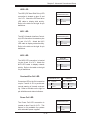
5-8 Connector Defi nitions ................................................................................... 5-12
ATX Main Power Connector ................................................................... 5-12
9-pin Power Connector .......................................................................... 5-12
NMI Button ............................................................................................. 5-12
Power LED ............................................................................................. 5-12
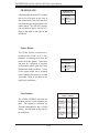
HDD LED ............................................................................................... 5-13
NIC1 LED ............................................................................................... 5-13
NIC2 LED ............................................................................................... 5-13
Overheat/Fan Fail LED .......................................................................... 5-13
Power Fail LED ...................................................................................... 5-13
PB UID/UID LED .................................................................................... 5-14
Power Button .......................................................................................... 5-14
Fan Headers .......................................................................................... 5-14
Universal Serial Bus Ports (USB0/1) ..................................................... 5-15
Universal Serial Bus Headers ................................................................ 5-15
Serial Port/Header .................................................................................. 5-15
ATX PS/2 Keyboard and PS/2 Mouse Ports ......................................... 5-15
Wake-On-LAN ........................................................................................ 5-16
Wake-On-Ring ........................................................................................ 5-16
SMB ........................................................................................................ 5-16
vii
Table of Contents

viii
Chassis Intrusion .................................................................................... 5-16
LAN 1/2 (Ethernet Ports) ....................................................................... 5-17
Compact Flash Card PWR Headers ...................................................... 5-17
5-9 Jumper Settings ............................................................................................ 5-17
Explanation of Jumpers ......................................................................... 5-17
CMOS Clear ........................................................................................... 5-18
VGA Enable/Disable ............................................................................... 5-18
LAN Enable/Disable ............................................................................... 5-18
SCSI Controller Enable/Disable ............................................................. 5-19
SCSI Termination Enable/Disable .......................................................... 5-19
Watch Dog Enable/Disable .................................................................... 5-19
Compact Flash Master/Slave ................................................................. 5-20
SMB to PCI-X/E Slots ............................................................................ 5-20
5-10 Onboard Indicators ....................................................................................... 5-20
LAN1/LAN2 LEDs .................................................................................. 5-20
Onboard Power LED .............................................................................. 5-21
Unit Identifi er .......................................................................................... 5-21
5-11 Floppy, IDE, SCSI and SATA Drive Connections ......................................... 5-22
Floppy Connector ................................................................................... 5-22
IDE Connectors ...................................................................................... 5-23
SATA Ports ............................................................................................. 5-23
SCSI Connectors ................................................................................... 5-24
Chapter 6: Advanced Chassis Setup
6-1 Static-Sensitive Devices ................................................................................. 6-1
6-2 Control Panel .................................................................................................. 6-2
6-3 System Fans ................................................................................................... 6-3
System Fan Failure .................................................................................. 6-3
Replacing System Fans ........................................................................... 6-3
6-4 Drive Bay Installation/Removal ...................................................................... 6-4
6-5 Power Supply ................................................................................................. 6-9
Power Supply Failure ............................................................................... 6-9
Removing/Replacing the Power Supply ................................................... 6-9
Chapter 7: BIOS
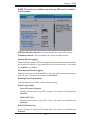
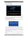
7-1 Introduction ..................................................................................................... 7-1
7-2 Running Setup ................................................................................................ 7-2
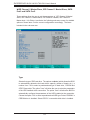
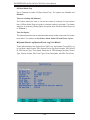
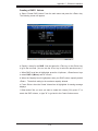
7-3 Main BIOS Setup ............................................................................................ 7-2
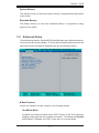
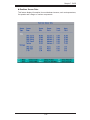
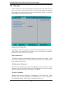
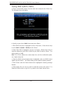
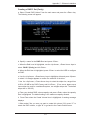
7-4 Advanced Setup ............................................................................................. 7-7
SUPERSERVER 6015X-3/6015X-T/6015X-8 User's Manual

Table of Contents
ix
7-5 Security ......................................................................................................... 7-24
7-6 Boot .............................................................................................................. 7-25
7-7 Exit ................................................................................................................ 7-26
Appendices:
Appendix A: BIOS POST Messages ........................................................................ A-1
Appendix B: BIOS POST Codes .............................................................................. B-1
Appendix C: Software Installation ........................................................................... C-1
Appendix D: System Specifi cations ........................................................................ D-1

Notes
x
S
UPERSERVER 6015X-3/6015X-T/6015X-8 User's Manual

Chapter 1
Introduction
1-1 Overview
The 6015X-3/6015X-T/6015X-8 is a high-end server comprised of two main subsys-
tems: the SC819TQ-700/SC819S-700 1U server chassis and the X7DBX-i/X7DBX-8
quad processor serverboard. Please refer to our web site for information on oper-
ating systems that have been certifi ed for use with the 6015X-3/6015X-T/6015X-8
(www.supermicro.com).
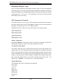
In addition to the serverboard and chassis, various hardware components have
been included with the 6015X-3/6015X-T/6015X-8, as listed below:
One (1) slim DVD-ROM drive [DVM-PNSC-824(B)]
Five (5) sets of 4-cm counter-rotating fans (FAN-0085)
One (1) front control panel cable (CBL-0087)
One (1) rackmount kit (CSE-PT51)
SAS Accessories (6015X-3 only)
One (1) SAS backplane (BPN-SAS-818TQ)
One (1) iPass cable (CBL-0172L-02)
SATA Accessories (6015X-T only)
One (1) SATA backplane (BPN-SAS-818TQ)
One (1) SATA data cable (CBL-0137-02)
Three (3) SATA drive carriers [MCP-220-00001-03(01)]
SCSI Accessories (6015X-8 only)
Three (3) SCA SCSI hard drive carriers [MCP-220-00001-03(01)]
One (1) SCSI backplane (CSE-SCA-818S)
One (1) Ultra320 SCSI cable (CBL-0063)
One (1) CD containing drivers and utilities
6015X-3/6015X-T/6015X-8 User's Manual
Chapter 1: Introduction
1-1

1-2
S
UPERSERVER 6015X-3/6015X-T/6015X-8 User's Manual
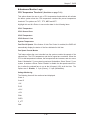
1-2 Serverboard Features
At the heart of the 6015X-3/6015X-T/6015X-8 lies the X7DBX-i/X7DBX-8, a dual pro-
cessor serverboard based on the Intel 5000P chipset. Below are the main features
of the X7DBX-i/X7DBX-8 (see Figure 1-1 for a block diagram of the chipset).
Processors
The X7DBX-i/X7DBX-8 supports dual Intel Xeon 5300/5100/5000 series processors
in 771-pin LGA sockets. Please refer to the serverboard description pages on our
web site for a complete listing of supported processors.
Memory
The X7DBX-i/X7DBX-8 has eight 240-pin DIMM slots supporting up to 32 GB of
FBD (Fully Buffered Data) ECC DDR2-667/533 SDRAM. DIMMs must be installed
in pairs (interleaved memory confi gurations only supported). Please refer to Sec-
tion 5-5 for details.
SAS Subsystem (6015X-3)
The 6015X-3 includes a SAS add-on card with an LSI 1068E controller chip to
support up to three SAS drives in the system, which are RAID 0, 1 and 10 sup-
ported. The SAS drives are hot-swappable units. Note: The operating system
you use must have RAID support to enable the hot-swap capability and RAID
function of the SAS drives.
Serial ATA Subsystem
An on-chip (ESB2) SATA controller is integrated into the X7DBX-i/X7DBX-8 to
provide a six-port, 3 Gb/sec Serial ATA subsystem, which is RAID 0, 1, 5 and 10
supported. The SATA drives are hot-swappable units. Note: The operating sys-
tem you use must have RAID support to enable the hot-swap capability and RAID
function of the Serial ATA drives.
SCSI Subsystem (6015X-8)
The X7DBX-8 includes an onboard Adaptec AIC-7902 dual-channel SCSI control-
ler, which supports four 80-pin SCA Ultra320 SCSI hard drives (RAID 0, 1 and 10
supported.). (Standard 1" drives are supported. SCA = Single Connection Attach-
ment.) The SCSI drives are connected to an SCA backplane that provides power,
bus termination and confi guration settings. The SCSI drives are hot-swappable

1-3
Chapter 1: Introduction
units. Note: The operating system you use must have RAID support to enable
the hot-swap capability and RAID function of the SCSI drives.
PCI Expansion Slots
The X7DBX-i/X7DBX-8 has two Universal PCI slots. The left slot supports one
PCI-Express x8 card or one 133 MHz PCI-X card. The right slot supports one
PCI-Express x4 card or one 100 MHz PCI-X card. An additional PCI-Express x8
slot is provided in the JPCIE3 slot. See Section 5-6 for details.
Onboard Controllers/Ports
One fl oppy drive controller and one onboard ATA/100 controller are provided to
support up to two IDE hard drives or ATAPI devices. The color-coded I/O ports
include one COM port, a VGA (monitor) port, two USB 2.0 ports, PS/2 mouse and
keyboard ports and two gigabit Ethernet ports.
Graphics Controller
The X7DBX-i/X7DBX-8 features an integrated video controller based on the ES1000
graphics chip. The ES1000 was designed specifi cally for servers, featuring low
power consumption, high reliability and superior longevity.
Other Features
Other onboard features that promote system health include onboard voltage moni-
tors, a chassis intrusion header, auto-switching voltage regulators, chassis and CPU
overheat sensors, virus protection and BIOS rescue.

1-4
S
UPERSERVER 6015X-3/6015X-T/6015X-8 User's Manual
1-3 Server Chassis Features
The 6015X-T/6015X-8 is a high-end, scaleable server platform built upon the
SC819TQ-700/SC819S-700 1U server chassis. The 2U in 1U
TM
design of the SC819
allows it to accommodate fi ve add-on cards (including an IPMI card), a capability
typically found only in 2U chassis and above. The following is a general outline of
the main features of the SC819TQ-700/SC819S-700 chassis.
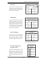
System Power
The SC819TQ-700/SC819S-700 features a single 700W power supply. Power must
be removed from the system before servicing or replacing the power supply.
SAS/SATA/SCSI Drives
The SC819TQ-700/SC819S-700 chassis was designed to support three SAS
(6015X-3), SATA (6015X-T) or SCSI (6015X-8) hard drives, which are hot-swap-
pable units. Note: The operating system you use must have RAID support to
enable the hot-swap capability of the SAS/SATA/SCSI drives.
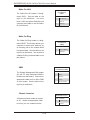
PCI Expansion Slots
Three standard size and one low-profi le PCI-E/PCI-X add-on cards may be used
with the SC819TQ-700/SC819S-700 chassis. See section 5-6 for details.
Control Panel
The SC819TQ-700/SC819S-700's control panel provides you with system monitor-
ing and control. LEDs indicate system power, HDD activity, network activity (2),
overheat/fan failure and UID (Unit Identifi er). A main power button and a UID button
is also included.
I/O Backplane
The SC819TQ-700/SC819S-700 is designed to be used in a 1U rackmount confi gu-
ration. Ports on the I/O backplane include one COM port, a VGA port, two USB 2.0
ports, PS/2 mouse and keyboard ports and two gigabit Ethernet ports.

1-5
Chapter 1: Introduction
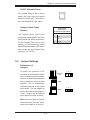
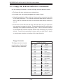
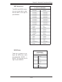
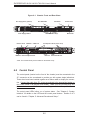
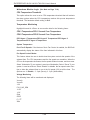
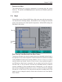
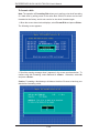
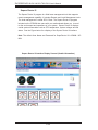
Figure 1-1. Intel 5000P Chipset:
System Block Diagram
Note: This is a general block diagram. Please see Chapter 5 for details.
USB 2.0
3.0Gb/S
KUMERAN
JPCIE3
PORT
PORT
PORT PORT
PORT PORT
PORT
PORT
#0
JPCIE2
PCI-EX4
PCI-EXP X16
PORT
#5
PCI-EX4
SCSI
7902
PXH-V
PCI-X 133
A
PCI-X SLOT ZCR
PCI-X 133
MCH
5000P
PROCESSOR#2
ESB2
PCI-EX8
GILGAL
GB LAN
FWH
RJ45
RJ45
LPC
COM2
COM1
SIO
W83627
FDD
PCI-EX4
JPCIX2
JPCIX1
VGA
PCI33MHz
ES1000
VGA
CONN
JPCIE1
PCI-EX8
PCI-EX8
EBUS CONN
EXPBUS
IDE CONN
ATA100
KB
VRM
ISL6307
#2,3#4
#6,7
#4 #3
#1,2
#0
VRM
ISL6307
PROCESSOR#1
MT/S
667/1067/1333
MT/S
PCI-X Slot
FBD DIMM
FBD DIMM
FBD DIMM
EHF
USB
PCIE X8
PCIE X4
FBDCHNL0
FBDCHNL1
FBDCHNL2
FBDCHNL3
#1A
FBD DIMM
SATA
PCI-EX4
#0-4
#0-5
#1B
#2A
#2B
#3A
#3B
#4A
#4B
667/1067/1333
MS
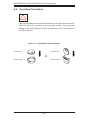
Cooling System
The SC819TQ-700/SC819S-700 chassis has an innovative cooling design that
features fi ve sets of 4-cm counter-rotating fans located in the middle section of the
chassis. There is a "Fan Speed Control Mode" setting in BIOS that allows chassis
fan speed to be determined by system temperature. The power supply module
also includes a cooling fan.

1-6
S
UPERSERVER 6015X-3/6015X-T/6015X-8 User's Manual
1-4 Contacting Supermicro
Headquarters
Address: SuperMicro Computer, Inc.
980 Rock Ave.
San Jose, CA 95131 U.S.A.
Tel: +1 (408) 503-8000
Fax: +1 (408) 503-8008
Web Site: www.supermicro.com
Europe
Address: SuperMicro Computer B.V.
Het Sterrenbeeld 28, 5215 ML
's-Hertogenbosch, The Netherlands
Tel: +31 (0) 73-6400390
Fax: +31 (0) 73-6416525
[email protected] (Technical Support)
[email protected] (Customer Support)
Asia-Pacifi c
Address: SuperMicro, Taiwan
4F, No. 232-1, Liancheng Rd.
Chung-Ho 235, Taipei County
Taiwan, R.O.C.
Tel: +886-(2) 8226-3990
Fax: +886-(2) 8226-3991
Web Site: www.supermicro.com.tw
Technical Support:
Tel: 886-2-8228-1366, ext.132 or 139

Chapter 2: Server Installation
2-1
Chapter 2
Server Installation
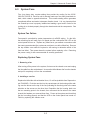
2-1 Overview
This chapter provides a quick setup checklist to get your 6015X-3/6015X-T/6015X-8
up and running. Following these steps in the order given should enable you to have
the system operational within a minimum amount of time. This quick setup assumes
that your system has come to you with the processors and memory pre-installed. If
your system is not already fully integrated with a serverboard, processors, system
memory etc., please turn to the chapter or section noted in each step for details
on installing specifi c components.
2-2 Unpacking the System
You should inspect the box the 6015X-3/6015X-T/6015X-8 was shipped in and note
if it was damaged in any way. If the server itself shows damage you should fi le a
damage claim with the carrier who delivered it.
Decide on a suitable location for the rack unit that will hold the 6015X-3/6015X-
T/6015X-8. It should be situated in a clean, dust-free area that is well ventilated.
Avoid areas where heat, electrical noise and electromagnetic fi elds are generated.
You will also need it placed near a grounded power outlet. Be sure to read the
Rack and Server Precautions in the next section.
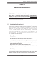
2-3 Preparing for Setup
The box the 6015X-3/6015X-T/6015X-8 was shipped in should include two sets of
rail assemblies, two rail mounting brackets and the mounting screws you will need
to install the system into the rack. Follow the steps in the order given to complete
the installation process in a minimum amount of time. Please read this section
in its entirety before you begin the installation procedure outlined in the sections
that follow.

2-2
S
UPERSERVER 6015X-3/6015X-T/6015X-8 User's Manual
Choosing a Setup Location
- Leave enough clearance in front of the rack to enable you to open the front door
completely (~25 inches).
- Leave approximately 30 inches of clearance in the back of the rack to allow for
suffi cient airfl ow and ease in servicing.
- This product is for installation only in a Restricted Access Location (dedicated
equipment rooms, service closets and the like).
- This product is not suitable for use with visual display work place devices according
to §2 of the the German Ordinance for Work with Visual Display Units.
Rack Precautions
- Ensure that the leveling jacks on the bottom of the rack are fully extended to the
fl oor with the full weight of the rack resting on them.
- In single rack installation, stabilizers should be attached to the rack.
- In multiple rack installations, the racks should be coupled together.
- Always make sure the rack is stable before extending a component from the
rack.
- You should extend only one component at a time - extending two or more simul-
taneously may cause the rack to become unstable.
Server Precautions
- Review the electrical and general safety precautions in Chapter 4.
- Determine the placement of each component in the rack before you install the
rails.
- Install the heaviest server components on the bottom of the rack fi rst, and then
work up.
- Use a regulating uninterruptible power supply (UPS) to protect the server from
power surges, voltage spikes and to keep your system operating in case of a power
failure.
-
Allow the hot plug SAS/SATA/SCSI drives and power supply modules to cool
before touching them.
-
Always keep the rack's front door and all panels and components on the servers
closed when not servicing to maintain proper cooling.
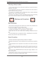
! !
Warnings and Precautions!

Chapter 2: Server Installation
2-3
Rack Mounting Considerations
Ambient Operating Temperature
If installed in a closed or multi-unit rack assembly, the ambient operating tempera-
ture of the rack environment may be greater than the ambient temperature of the
room. Therefore, consideration should be given to installing the equipment in an
environment compatible with the manufacturer’s maximum rated ambient tempera-
ture (Tmra).
Reduced Airfl ow
Equipment should be mounted into a rack so that the amount of airfl ow required
for safe operation is not compromised.
Mechanical Loading
Equipment should be mounted into a rack so that a hazardous condition does not
arise due to uneven mechanical loading.
Circuit Overloading
Consideration should be given to the connection of the equipment to the power
supply circuitry and the effect that any possible overloading of circuits might have
on overcurrent protection and power supply wiring. Appropriate consideration of
equipment nameplate ratings should be used when addressing this concern.
Reliable Ground
A reliable ground must be maintained at all times. To ensure this, the rack itself
should be grounded. Particular attention should be given to power supply connec-
tions other than the direct connections to the branch circuit (i.e. the use of power
strips, etc.).

2-4
S
UPERSERVER 6015X-3/6015X-T/6015X-8 User's Manual
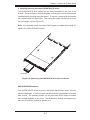
2-4 Installing the System into a Rack
This section provides information on installing the 6015X-3/6015X-T/6015X-8 into a
rack unit with the rack rails provided. If the system has already been mounted into
a rack, you can skip ahead to Sections 2-5 and 2-6. There are a variety of rack
units on the market, which may mean the assembly procedure will differ slightly.
You should also refer to the installation instructions that came with the rack unit
you are using.
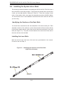
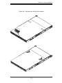
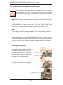
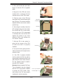
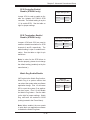
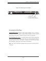
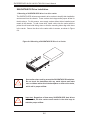
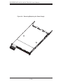
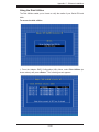
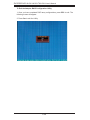
Identifying the Sections of the Rack Rails
You should have received two rack rail assemblies in the rack mounting kit. Each
assembly consists of two sections: an inner fi xed chassis rail that secures directly
to the server chassis and an outer fi xed rack rail that secures directly to the rack
itself (see Figure 2-1). Two pairs of short brackets to be used on the front side of
the outer rails are also included.
Installing the Inner Rails
Both the left and right side inner rails have been pre-attached to the chassis.
Proceed to the next step. A
Figure 2-1. Identifying the Sections of the Rack Rails
(right side rail shown)
Page is loading ...
Page is loading ...
Page is loading ...
Page is loading ...
Page is loading ...
Page is loading ...
Page is loading ...
Page is loading ...
Page is loading ...
Page is loading ...
Page is loading ...
Page is loading ...
Page is loading ...
Page is loading ...
Page is loading ...
Page is loading ...
Page is loading ...
Page is loading ...
Page is loading ...
Page is loading ...
Page is loading ...
Page is loading ...
Page is loading ...
Page is loading ...
Page is loading ...
Page is loading ...
Page is loading ...
Page is loading ...
Page is loading ...
Page is loading ...
Page is loading ...
Page is loading ...
Page is loading ...
Page is loading ...
Page is loading ...
Page is loading ...
Page is loading ...
Page is loading ...
Page is loading ...
Page is loading ...
Page is loading ...
Page is loading ...
Page is loading ...
Page is loading ...
Page is loading ...
Page is loading ...
Page is loading ...
Page is loading ...
Page is loading ...
Page is loading ...
Page is loading ...
Page is loading ...
Page is loading ...
Page is loading ...
Page is loading ...
Page is loading ...
Page is loading ...
Page is loading ...
Page is loading ...
Page is loading ...
Page is loading ...
Page is loading ...
Page is loading ...
Page is loading ...
Page is loading ...
Page is loading ...
Page is loading ...
Page is loading ...
Page is loading ...
Page is loading ...
Page is loading ...
Page is loading ...
Page is loading ...
Page is loading ...
Page is loading ...
Page is loading ...
Page is loading ...
Page is loading ...
Page is loading ...
Page is loading ...
Page is loading ...
Page is loading ...
Page is loading ...
Page is loading ...
Page is loading ...
Page is loading ...
Page is loading ...
Page is loading ...
Page is loading ...
Page is loading ...
Page is loading ...
Page is loading ...
Page is loading ...
Page is loading ...
Page is loading ...
Page is loading ...
Page is loading ...
Page is loading ...
Page is loading ...
Page is loading ...
Page is loading ...
Page is loading ...
Page is loading ...
Page is loading ...
Page is loading ...
Page is loading ...
Page is loading ...
Page is loading ...
Page is loading ...
Page is loading ...
Page is loading ...
Page is loading ...
Page is loading ...
Page is loading ...
Page is loading ...
Page is loading ...
Page is loading ...
Page is loading ...
Page is loading ...
Page is loading ...
Page is loading ...
Page is loading ...
Page is loading ...
Page is loading ...
-
 1
1
-
 2
2
-
 3
3
-
 4
4
-
 5
5
-
 6
6
-
 7
7
-
 8
8
-
 9
9
-
 10
10
-
 11
11
-
 12
12
-
 13
13
-
 14
14
-
 15
15
-
 16
16
-
 17
17
-
 18
18
-
 19
19
-
 20
20
-
 21
21
-
 22
22
-
 23
23
-
 24
24
-
 25
25
-
 26
26
-
 27
27
-
 28
28
-
 29
29
-
 30
30
-
 31
31
-
 32
32
-
 33
33
-
 34
34
-
 35
35
-
 36
36
-
 37
37
-
 38
38
-
 39
39
-
 40
40
-
 41
41
-
 42
42
-
 43
43
-
 44
44
-
 45
45
-
 46
46
-
 47
47
-
 48
48
-
 49
49
-
 50
50
-
 51
51
-
 52
52
-
 53
53
-
 54
54
-
 55
55
-
 56
56
-
 57
57
-
 58
58
-
 59
59
-
 60
60
-
 61
61
-
 62
62
-
 63
63
-
 64
64
-
 65
65
-
 66
66
-
 67
67
-
 68
68
-
 69
69
-
 70
70
-
 71
71
-
 72
72
-
 73
73
-
 74
74
-
 75
75
-
 76
76
-
 77
77
-
 78
78
-
 79
79
-
 80
80
-
 81
81
-
 82
82
-
 83
83
-
 84
84
-
 85
85
-
 86
86
-
 87
87
-
 88
88
-
 89
89
-
 90
90
-
 91
91
-
 92
92
-
 93
93
-
 94
94
-
 95
95
-
 96
96
-
 97
97
-
 98
98
-
 99
99
-
 100
100
-
 101
101
-
 102
102
-
 103
103
-
 104
104
-
 105
105
-
 106
106
-
 107
107
-
 108
108
-
 109
109
-
 110
110
-
 111
111
-
 112
112
-
 113
113
-
 114
114
-
 115
115
-
 116
116
-
 117
117
-
 118
118
-
 119
119
-
 120
120
-
 121
121
-
 122
122
-
 123
123
-
 124
124
-
 125
125
-
 126
126
-
 127
127
-
 128
128
-
 129
129
-
 130
130
-
 131
131
-
 132
132
-
 133
133
-
 134
134
-
 135
135
-
 136
136
-
 137
137
-
 138
138
-
 139
139
-
 140
140
-
 141
141
-
 142
142
-
 143
143
-
 144
144


Supermicro SUPERSERVER 6015X-3 User manual
- Category
- Server barebones
- Type
- User manual
- This manual is also suitable for
Ask a question and I''ll find the answer in the document
Finding information in a document is now easier with AI
Related papers
-
Supermicro SUPERSERVER 8044T-8R User manual
-
-
-
-
-
-
SUPER MICRO Computer SuperServer 6015B-T+V, Silver User manual
-
-
-
Other documents
-
Inter-Tech 88887092 Datasheet
-
-
-
-
-
 Penguin Computing Relion 1400 User manual
-
HP 6-Port SATA RAID User manual
-
NEC Express5800/120Ra-1 User guide
-
Intel AXXRMS2LL040 Hardware User's Manual
-
 Wiley 978-0-470-11411-7 Datasheet

