Page is loading ...

MQ POWER
DCA-85SSJU
WHISPERWATT
TM
GENERATOR
(STANDARD)
Revision #2 (12/21/01)
MULTIQUIP INC
..
..
. PARTS DEPARTMENT:
18910 WILMINGTON AVE. 800-427-1244
CARSON, CALIFORNIA 90746 FAX: 800-672-7877
310-537-3700
SERVICE DEPARTMENT:
800-421-1244 800-835-2551
FAX: 310-537-3927 FAX: 310-638-8046
E-mail:[email protected] • www:multiquip.com
© COPYRIGHT 2001, MULTIQUIP INC.
PARTS LIST No. M2872300104
PARTS AND OPERATION MANUAL

PAGE 2 — DCA-85SSJU — PARTS AND OPERATION MANUAL — REV. #2 (12/21/01)

DCA-85SSJU — PARTS AND OPERATION MANUAL— REV. #2 (12/21/01) — PAGE 3
HERE'S HOW TO GET HELP
PLEASE HAVE THE MODEL AND SERIAL NUMBER
ON-HAND WHEN CALLING
PARTS DEPARTMENT
800/427-1244 or 310/537-3700
FAX: 800/672-7877 or 310/637-3284
SERVICE DEPARTMENT
800/835-2551 or 310/537-3700
FAX: 310/638-8046
WARRANTY DEPARTMENT
800/835-2551 or 310/537-3700
FAX: 310/638-8046
MAIN
800/421-1244 or 310/537-3700
FAX: 310/537-3927

PAGE 4 — DCA-85SSJU — PARTS AND OPERATION MANUAL — REV. #2 (12/21/01)
TABLE OF CONTENTS
NOTE
Specification and part number
are subject to change without
notice.
Here's How To Get Help ............................................... 3
Parts Ordering Procedures .......................................... 5
Rules for Safe Operation .......................................... 6-9
Towing Safety Precaution .......................................... 10
Trailer Safety Guidelines ....................................... 11-17
Trailer Wiring Diagram ................................................ 18
Electrical Brake Troubleshooting ................................ 19
Hydraulic Brake Troubleshooting ................................ 20
Operation and Safety Decals................................ 21-22
DCA-85SSJU Specifications ..................................... 23
General Information ................................................... 24
Major Components .................................................... 25
Dimensions ................................................................ 26
Control Panel Descriptions ................................... 28-29
Engine Operating Panel Descriptions ................... 30-31
Output Terminal Panel Overview ........................... 32-39
Installation ............................................................ 40-41
Pre Setup ............................................................. 42-45
Load Application ........................................................ 46
Generator Start-up Procedure .............................. 47-49
Generator Start-up Procedure, Auto .......................... 50
Generator Shut-Down Procedure ............................... 51
Maintenance ......................................................... 52-53
Generator Wiring Diagram .......................................... 54
Engine Wiring Diagram .............................................. 55
Engine Troubleshooting ......................................... 56-57
Generator/Engine Troubleshooting ............................. 58
Engine Controller Troubleshooting .............................. 59
Explanation of Code in Remarks Column .................. 60
Suggested Spare Parts ............................................. 61
MQPower DCA 85SSJUMQPower DCA 85SSJU
MQPower DCA 85SSJUMQPower DCA 85SSJU
MQPower DCA 85SSJU
AC GeneratorAC Generator
AC GeneratorAC Generator
AC Generator
Generator Assembly ............................................. 62-63
Control Box Assembly ........................................... 64-67
Engine & Radiator Assembly................................. 68-71
Engine Operating Panel Assembly ........................ 72-73
Output Terminal Assembly ..................................... 74-75
Battery Assembly .................................................. 76-77
Muffler Assembly .................................................. 78-79
Fuel Tank Assembly ............................................ 80-81
Enclosure Assembly ............................................. 82-85
Rubber Seal Assembly .......................................... 86-87
Name Plate And Decals ........................................ 88-89
Terms and Condition of Sale — Parts ....................... 90

DCA-85SSJU — PARTS AND OPERATION MANUAL— REV. #2 (12/21/01) — PAGE 5
PARTS ORDERING PROCEDURES
Get special freight allowances
when you order 10 or more
line items via FAX!**
■■
■■
■
UPS Ground Service at no charge for freight
■■
■■
■
PS Third Day Service at one-half of actual freight cost
No other allowances on freight shipped by any other carrier.
**Common nuts, bolts and washers (all items under $1.00 list price)
do not count towards the 10+ line items.
*DISCOUNTS ARE SUBJECT TO CHANGE*
Fax order discount and UPS special programs revised June 1, 1995
For faxed orders only
UPS
Special
Earn Extra Discounts when
you order by FAX!
All parts orders which include complete part numbers
and are received by fax qualify for the following extra
discounts:
Number of
line items ordered Additional Discount
1-9 items 3%
10+ items** 5%
Now! Direct TOLL-FREE access
to our Parts Department!
Toll-free nationwide:
800-421-1244
Toll-free FAX:
800/6-PARTS-7 • 800-672-7877
■■
■■
■ Dealer account number
■■
■■
■ Dealer name and address
■■
■■
■ Shipping address (if different than billing address)
■■
■■
■ Return fax number
■■
■■
■ Applicable model number
■■
■■
■ Quantity, part number and description of each part
■■
■■
■ Specify preferred method of shipment:
•
UPS Ground
•
UPS Second Day or Third Day*
•
UPS Next Day*
•
Federal Express Priority One (please provide us with your Federal
Express account number)*
•
Airborne Express*
•
Truck or parcel post
*Normally shipped the same day the order is received, if prior to 2PM west coast time.
Extra Fax DiscountExtra Fax Discount
Extra Fax DiscountExtra Fax Discount
Extra Fax Discount
for Domestic USAfor Domestic USA
for Domestic USAfor Domestic USA
for Domestic USA
Dealers OnlyDealers Only
Dealers OnlyDealers Only
Dealers Only

PAGE 6 — DCA-85SSJU — PARTS AND OPERATION MANUAL — REV. #2 (12/21/01)
RULES FOR SAFE OPERATION
■
NEVER touch the hot exhaust
manifold, muffler or cylinder. Allow
these parts to cool before servicing
engine or generator.
■
The engine of this generator requires an adequate free
flow of cooling air. Never operate the generator in any
enclosed or narrow area where free flow of the air is
restricted. If the air flow is restricted it will cause serious
damage to the generator or engine and may cause injury
to people. The generator engine gives off DEADLY carbon
monoxide gas.
■
High Temperatures – Allow the engine to cool before
adding fuel or performing service and maintenance
functions. Contact with
hot
components can cause serious
burns.
CAUTION:CAUTION:
CAUTION:CAUTION:
CAUTION:
Failure to follow instructions in this manual
may lead to serious injury or even death!
This equipment is to be operated by trained
and qualified personnel only! This equipment
is for industrial use only.
The following safety guidelines should always be used when
operating the DCA-85SSJU portable generator:
GENERAL SAFETY
■
DO NOT operate or service this equipment before
reading this entire manual.
■
This equipment should not be operated by
persons under 18 years of age.
■
NEVER operate this equipment without proper
protective clothing, shatterproof glasses,
steel-toed boots and other protective devices
required by the job.
■
NEVER operate this equipment when not feeling
well due to fatigue, illness or taking medicine.
■
NEVER operate this equipment under the
influence or drugs or alcohol.
■
NEVER use accessories or attachments, which are not
recommended by MQ Power for this equipment. Damage
to the equipment and/or injury to user may result.
■
Manufacturer does not assume responsibility for any
accident due to equipment modifications.
■
Whenever necessary, replace nameplate, operation and
safety decals when they become difficult read.
■
Always check the machine for loosened threads or bolts
before starting.
CAUTIONCAUTION
CAUTIONCAUTION
CAUTION
:
■
Always use extreme caution when
working with flammable liquids. When
refueling, stop the engine and allow it to
cool. DO NOT smoke around or near the
machine. Fire or explosion could result
from fuel vapors, or if fuel is spilled on a
hot engine.
NEVER operate the generator in an
explosive atmosphere or near combustible materials. An
explosion or fire could result causing severe
bodily harm
or even death.
Topping-off to filler port is dangerous, as it tends to spill
fuel.
Always refuel in a well-ventilated area,
away from sparks and open flames.

DCA-85SSJU — PARTS AND OPERATION MANUAL— REV. #2 (12/21/01) — PAGE 7
RULES FOR SAFE OPERATION
CAUTIONCAUTION
CAUTIONCAUTION
CAUTION
:
■
Backfeed to a utility system can cause electrocution
and.or property damage. Do not connect to any
building's electrical system except through an approved
device or after building main switch is opened.
Never use damaged or worn cables when
connecting power tools or equipment to the
generator. Make sure power connecting
cables are securely connected to the
generator’s output terminals, insufficient
tightening of the terminal connections may
cause damage to the generator and
electrical shock.
CAUTIONCAUTION
CAUTIONCAUTION
CAUTION
:
DO NOT touch or open any of the below
mentioned components while the
generator is running. Always allow
sufficient time for the engine and generator
to cool before performing maintenance.
Radiator
1. Radiator Cap - Removing the radiator cap while the
engine is hot will result in high pressurized, boiling water
to gush out of the radiator, causing severe scalding to
any persons in the general area of the generator.
2. Coolant Drain Plug - Removing the coolant drain plug
while the engine is hot will result in hot coolant to gush
out of the coolant drain plug, therefore causing severe
scalding to any persons in the general area of the
generator.
3. Engine Oil Drain Plug - Removing the engine oil drain
plug while the engine is hot will result in hot oil to gush
out of the oil drain plug, therefore causing severe
scalding to any persons in the general area of the
generator.
CAUTIONCAUTION
CAUTIONCAUTION
CAUTION
:
CAUTIONCAUTION
CAUTIONCAUTION
CAUTION
:
NEVER touch output terminals during operation. This is
extremely dangerous.
Always stop the machine when
contact with the output terminals.

PAGE 8 — DCA-85SSJU — PARTS AND OPERATION MANUAL — REV. #2 (12/21/01)
RULES FOR SAFE OPERATION
NEVER Run engine without air filter. Severe engine
damage may occur.
Always service air cleaner frequently to prevent carburetor
malfunction.
Always disconnect the battery before performing service
on the generator.
Always be sure the operator is familiar with proper safety
precaution s and operations techniques before using
generator.
Always store equipment properly when not in use.
Equipment should be stored in a clean, dry location out of
the reach of children.
DO NOT leave the generator running in the manual mode
unattended.
DO NOT allow unauthorized people to operate this
equipment.
Always read, understand, and follow procedures in
Operator’s Manual before attempting to operate equipment.
Refer to the
John Deere Engine Owner's Manual
for
engine technical questions or information.
Loading and Unloading (Crane)
Before lifting, make sure the generator's lifting hook is
secure and that there is no apparent damage to the
generator itself (loose screws, nuts and bolts). If any
part is loose or damaged, please take corrective action
before lifting.
Always drain fuel prior to lifting.
Always make sure crane or lifting device has been
properly secured to the hook of guard frame on generator.
NEVER lift the machine while the engine is running.
Use adequate lifting cable (wire or rope) of sufficient
strength.
When lifting the generator, always use the balanced
center-point suspension hook and lift straight upwards.
NEVER allow any person or animal to stand underneath
the machine while lifting.
When loading the generator on a truck, be sure to use
the front and back frame bars as a means to secure the
generator during transport.
Battery
Never over fill the battery with water
above the upper limit.
CAUTIONCAUTION
CAUTIONCAUTION
CAUTION
:
The battery contains acids that can cause injury to the eyes
and skin. To avoid eye irritation, always wear safety glasses.
Use well insulated gloves when picking up the battery. Use
the following guidelines when handling the battery:
1. DO NOT drop the battery. There is the possibility of risk
that the battery may explode.
2. DO NOT expose the battery to open flames, sparks,
cigarettes etc. The battery contains combustible gases
and liquids. If these gases and liquids come in contact
with a flame or spark, an explosion could occur.
3. Always keep the battery charged. If the battery is not
charged a buildup of combustible gas will occur.
4. Always keep battery charging and booster cables in good
working condition. Repair or replace all worn cables.
5. Always recharge the battery in an open air environment,
to avoid risk of a dangerous concentration of combustible
gases.
6. In case the battery liquid (dilute sulfuric acid) comes in
contact with
clothing or skin
, rinse skin or clothing
immediately with plenty of water.
7. In case the battery liquid (dilute sulfuric acid) comes in
contact with your eyes, rinse eyes immediately with
plenty of water, then contact the nearest doctor or hospital,
and seek medical attention.

DCA-85SSJU — PARTS AND OPERATION MANUAL— REV. #2 (12/21/01) — PAGE 9
Transporting
Always shutdown engine before transporting.
Tighten fuel tank cap securely.
Drain fuel when transporting generator over long distances
or bad roads.
Always tie-down the generator during transportation by
securing the generator.
If generator is mounted on a trailer, make sure trailer
complies with all local and state safety transportation
laws. See page 10 for basic towing procedures.
Emergencies
Always know the location of the nearest
fire extinguisher
and
first aid kit
. Know the location of the nearest telephone.
Also know the phone numbers of the nearest
ambulance
,
doctor
and
fire department
.
Maintenance Safety
NEVER lubricate components or attempt service on a
running machine.
Always allow the machine a proper amount of time to
cool before servicing.
Keep the machinery in proper running condition.
Fix damage to the machine immediately and always
replace broken parts.
Dispose of hazardous waste properly. Examples of
potentially hazardous waste are used motor oil, coolant,
fuel, and fuel filters.
DO NOT use plastic containers to dispose of hazardous
waste.
DO NOT pour waste, oil, coolant or fuel directly onto the
ground, down a drain or into any water source.
RULES FOR SAFE OPERATION

PAGE 10 — DCA-85SSJU — PARTS AND OPERATION MANUAL — REV. #2 (12/21/01)
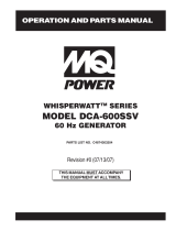
To reduce the possibility of an accident while transporting
the generator on public roads, always make sure the trailer
(Figure 1) that supports the generator and the towing vehicle
are in good operating condition and both units are
mechanically sound.
The following list of suggestions should be used when towing
your generator:
CAUTION :CAUTION :
CAUTION :CAUTION :
CAUTION :
Towing Safety Precautions
Check with your county or state safety
towing regulations department before towing
your generator.
Make sure the hitch and coupling of the towing vehicle
are rated equal to, or greater than the trailer "gross vehicle
weight rating" (GVWR).
ALWAYS inspect the hitch and coupling for wear. NEVER
tow a trailer with defective hitches, couplings, chains
etc.
Check the tire air pressure on both towing vehicle and
trailer. Also check the tire tread wear on both vehicles.
ALWAYS make sure the trailer is equipped with a "Safety
Chain".
DCA-85SSJU — TOWING RULES FOR SAFE OPERATION
ALWAYS attach trailer’s safety chain to bumper of towing
vehicle.
ALWAYS make sure the vehicle and trailer directional,
backup, brake, and trailer lights are connected and
working properly.
The maximum speed for highway towing is 45 MPH
unless posted otherwise. Recommended off-road towing
is not to exceed 10 MPH or less depending on type of
terrain.
Place
chocked blocks
underneath wheel to prevent
rolling, while parked.
Place
support blocks
underneath the trailer’s bumper to
prevent tipping, while parked.
Use the trailer’s hand winch to adjust the height of the
trailer, then insert locking pin to lock wheel stand in place,
while parked.
Avoid sudden stops and starts. This can cause skidding,
or jack-knifing. Smooth, gradual starts and stops will
improve gas milage.
Avoid sharp turns to prevent rolling.
.Remove wheel stand when transporting.
DO NOT transport generator with fuel in tank.
Figure 1. Generator with Trailer

DCA-85SSJU — PARTS AND OPERATION MANUAL— REV. #2 (12/21/01) — PAGE 11
Explanation of Chart:
This section is to provide the user with trailer service and
maintenance information. The service and maintenance
guidelines referenced in this section apply to a wide range of
trailers. Periodic inspection of the trailer will ensure safe
towing of the equipment and will prevent damage to the equip-
ment and personal injury.
It is the purpose of this section to cover the major mainte-
nance components of the trailer. The following trailer com-
ponents will be discussed in this section:
Brakes
Tires
Lug Nut Torquing
Suspension
Electrical
Brake Troubleshooting Tables
Use the following definitions with reading Table 1.
1. Fuel Cell - Provides an adequate amount of fuel for the
equipment in use. Fuel cells must be empty when trans-
porting equipment.
2. Braking System - System employed in stopping the
trailer. Typical braking systems are electric, surge, hy-
draulic, hydraulic-surge and air.
3. GVWR- Gross Vehicle Weight Rating (GVWR), is the
maximum number of pounds the trailer can carry, in-
cluding the fuel cell (empty).
DCA-85SSJU — TRAILER-SAFETY GUIDELINES
4. Frame Length - This measurement is from the ball
hitch to the rear bumper (reflector).
5. Frame Width - This measurement is from fender to
fender.
6. Jack Stand - Trailer support device with maximum
pound requirement from the tongue of the trailer.
7. Coupler - Type of hitch used on the trailer for towing.
8. Tire Size - Indicates the diameter of the tire in inches
(10,12,14, etc.), and the width in millimeters
(175,185,205, etc.). The tire diameter must match the
diameter of the tire rim.
9. Tire Ply - The tire ply (layers) number is rated in letters;
2-ply,4-ply,6-ply, etc.
10. Wheel Hub - The wheel hub is connected to the trailer’s
axle.
11. Tire Rim - Tires mounted on a tire rim. The tire rim must
match the size of the tire.
12. Lug Nuts - Used to secure the wheel to the wheel hub.
Always use a torque wrench to tighten down the lug
nuts. See Table 4 and Figure 5 or lug nut tightening and
sequence.
13. Axle - Indicates the maximum weight the axle can sup-
port in pounds, and the diameter of the axle expressed
in inches (see Table 3). Please note that some trailers
have a double axle. This will be shown as 2-6000 lbs.,
meaning two axles with a total weight capacity of 6000
pounds.
14. Suspension - Protects the trailer chassis from shocks
transmitted through the wheels. Types of suspension
used are leaf, Q-flex, and air ride.
15. Electrical - Electrical connectors (looms) are provided
with the trailer so the brake lights and turn signals can
be connected to the towing vehicle.
16. Application - Indicates which units can be employed
on a particular trailer.
CAUTION:CAUTION:
CAUTION:CAUTION:
CAUTION:
ALWAYS make sure the trailer is in good
operating condition. Check the tires for
proper inflation and wear. Also check the
wheel lug nuts for proper tightness.

PAGE 12 — DCA-85SSJU — PARTS AND OPERATION MANUAL — REV. #2 (12/21/01)
snoitacificepS.1elbaT
LEDOM NOITACILPPA LEUF
LLEC
EKARB
METSYS
RWVG EMARF
HTGNEL
EMARF
HTDIW
KCAJ
DNATS
W01-RLRT ,522WDS
003WLT,052WGS
ONONSBL0091"69"05.BL008
LEEHWTLITLLUF
01-RLRT ,21GLT,01ACD
51-ACD
ONONSBL0091"69"05.BL00
8
LEEHWTLITLLUF
FX01-RLRT ,21-GLT,01ACD
003-WLT,51ACD
LAG25ONSBL0091"69"05.BL008
LEEHWTLITLLUF
W522-RLRT ,SREDLEW
S
S0007AD
ONONSBL0022"58"24.BL008
LEEHWTLITLLUF
004WLB-RLRT 004-WLBONCIRTCELESBL0072"451TSAM/W
"421O/W
"55
)LLAT"87(
.BL
008
LEEHWTLITLLUF
X05-RLRT 52-ACDONONSBL0072"421"55.BL008
LEEHWTLITLLUF
FX05-RLRT 52-ACDLAG14ONSBL0072"421"55.BL008
LEEH
WTLITLLUF
W07-RLRT 07,06-,54-ACDONEGRUSSBL0007"681"77.BL0002
DAPTALF
X07-RLRT 07,06-,54-ACDTPOEGRUSSBL0007"831"66.BL00
02
DAPTALF
FX07-RLRT 07,06-,54-ACDLAG35EGRUSSBL0007"831"66.BL0002
DAPTALF
FX001-RLRT 521,001-ACDLAG051EGRUSCILUARDY
HSBL0007"091"67.BL0002
DAPTALF
521/58-RLRT ,001,58-ACD
521
LAG541CILUARDYHSBL00001"681"77.BL0002
DAPTALF
FX051-RLRT 08
1,051-ACDLAG002EGRUSCILUARDYHSBL06111"402"48.BL0005
DAPTALF
FX022-RLRT 022-ACDLAG052EGRUSCILUARDYHSBL00041"222"38.BL
0005
DAPTALF
FX003-RLRT 003-ACDLAG052EGRUSCILUARDYHSBL00081"832"38.BL0005
DAPTALF
FX004-RLRT 004-ACDLAG053CIRTCELESB
L00081"832"38.BL0005
DAPTALF
FX006-RLRT 008,006-ACDLAG055RIASBL00003"483"69.BL0005
DAPTALF
XS008-RLRT 008,006-ACDLAG0
55RIASBL00003"483"69.BL0005
DAPTALF
DCA-85SSJU —TRAILER-SPECIFICATIONS

DCA-85SSJU — PARTS AND OPERATION MANUAL— REV. #2 (12/21/01) — PAGE 13
)t'noC(snoitacificepS.1elbaT
LEDOM RELPUOC SERIT SLEEHW ELXA SBUH NOISNEPSUS LACIRTCELE
W01-RLRT SSALCLLAB"2
ELBATSUJDA2
C31-571"05.4X"312X2#0022GUL5FAEL3/WMOOLERIW4
TALFELOP4
01-RLRT SSALCLLAB"2
ELBAT
SUJDA2
C31-571"5.4X"312X2#0022GUL5FAEL3TALFELOP4
FX01-RLRT SSALCLLAB"2
ELBATSUJDA2
C31-571"5.4X"312X2#0022GUL5FAEL3T
ALFELOP4
W522-RLRT SSALCLLAB"2
ELBATSUJDA2
B31-571"5.4X312X2#0022GUL5XELFQTALFELOP4
004WLB-RLRT SSALCLLAB"2
ELBAT
SUJDA2
C31-571"5.4X312X2#0022GUL5FAEL3TALFELOP4
X05-RLRT SSALCLLAB"2CRL31-87B"05.4X"31.sbl0053
"8/3-2
GUL5FAEL4REBBU
RELOP4
TALF
FX05-RLRT SSALCLLAB"2CRL31-87B"05.4X"31.sbl0053
"8/3-2
GUL5FAEL4REBBURELOP4
TALF
W07-RLRT SSALCLLAB"2
E
LBATSUJDA"3
C41-502
)4(SAIB
"5X"41.sbl0053
"3
GUL5FAEL5REBBURELOP4
TALF
X07-RLRT SSALCLLAB"2
ELBATSUJDA"3
C41-502
)
4(SAIB
"5X"41sbl0053
"3
GUL5FAEL5REBBURELOP4
TALF
FX07-RLRT SSALCLLAB"2
ELBATSUJDA"3
C41-502
)4(SAIB
"5X"41.sbl0053
"3
GUL5FAEL5REBBURELOP4
TALF
FX001-RLRT 6/5-2ELBATSUJDA
EYE"3TPO
C51-502
)4(SAIB
"5.5X"41sbl0053
"3
GUL5FAEL5MOOLERI
W4
521/58-RLRT 6/5-2ELBATSUJDA
EYE"3TPO
D51R57/522TS
)4(LAIDAR
"6x"41sbl0006-)2(GUL6FAEL7MOOLERIW4
FX051-RLRT EYE
LLAB"3E61-057
)4(SAIB
"7X"61sbl0006-)2(GUL8FAEL7MOOLERIW4
FX022-RLRT EYE"3
ELBATSUJDA
E61R58/532TS
)4(LAIDAR
"7X"6
1sbl0007-)2(GUL8XELFQMOOLERIW4
FX003-RLRT EYE"3
ELBATSUJDA
E61R58/532TS
)6(LAIDAR
"7X"61sbl0006-)2(GUL8XELFQMOOLERI
W4
FX004-RLRT EYE"3
ELBATSUJDA
E61R58/532TS
)6(LAIDAR
"7X"61.sbl0007-)3(GUL8XELFQMOOLERIW4
FX006-RLRT LEEHWHT5H5.7
1R57/512TS
)8(LAIDAR
"7X"61sbl00001-)3(GUL8FAEL7MOOLERIW6
RA008-RLRT LEEHWHT5H5.71R57/512TS
)8(LAIDAR
"7X"61sbl00
001-)3(GUL8EDIR-RIAMOOLERIW6
DCA-85SSJU —TRAILER-SPECIFICATIONS

PAGE 14 — DCA-85SSJU — PARTS AND OPERATION MANUAL — REV. #2 (12/21/01)
DCA-85SSJU —TRAILER SAFETY GUIDELINES
Brakes
If your trailer has a braking system, the brakes should be
inspected the first 200 miles of operation. This will allow
the brake shoes and drums to seat properly. After the first
200 mile interval, inspect the brakes every 3,000 miles. If
driving over rough terrain, inspect the brakes more
frequently.
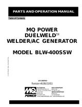
Electric Brakes
Electrically actuated brakes (Figure 2) are similar to
hydraulic brakes. The basic difference is that hydraulic
brakes are actuated by an electromagnet.
Listed below are some of the advantages that electric
brakes have over hydraulic brakes:
Brake system can be manually adjusted to provide
the corrected braking capability for varying road and
load conditions
Brake system can be modulated to provide more or
less braking force, thus easing the brake load on the
towing vehicle
Brake system has very little lag time between the time
the vehicle’s brakes are actuated and the trailer’s brakes
are actuated
Brake system can provide an independent emergency
brake system
Remember in order to properly synchronize the tow vehicle’s
braking to the trailer’s braking, can only be accomplished
by road testing. Brake lockup, grabbiness or harshness is
due to lack of synchronization between the tow vehicle
and the trailer being towed or under-adjusted brakes.
Before any brake synchronizations adjustments can be
made, the trailer brakes should be burnished-in by applying
the brakes 20-30 times with approximately a 20 m.p.h.
decrease in speed, e.g. 40 m.p.h. to 20 m.p.h. Allow ample
time for brakes to cool between application. This allows
the brake shoes to slightly be seated into the brake drum
surface.
Figure 2 displays the major electric brake components that
will require inspection and maintenance. Please inspect
these components as required.
Electric Brake Adjustment
1. Place the trailer on jack stands. Make sure the jack
stands are placed on secure level ground.
2. Check the wheel and drum for free rotation.
3. Remove the adjusting hole cover from the adjusting
slot at the bottom brake backing plate.
4. With a screwdriver or standard adjusting tool, rotate
the star wheel of the adjuster assembly to expand the
brake shoes.
5. Adjust the brake shoes outward until the pressure of
the lining against the wheel drum makes the wheel
difficult to turn.
6. Rotate the star wheel in the opposite direction until the
wheel rotates freely with slight lining drag.
7. Replace the adjusting hole cover and lower the trailer
to the ground.
8. Repeat steps 1 through 6 on the remaining brakes.

DCA-85SSJU — PARTS AND OPERATION MANUAL— REV. #2 (12/21/01) — PAGE 15
DCA-85SSJU — TRAILER SAFETY GUIDELINES
Hydraulic/Air/Surge Brakes
Hydraulic brakes (Figure 3) should not require any special
attention with the exception of routine maintenance such
as shoe and lining replacement. These brakes can be
adjusted in the same manner as electric brakes. Brake
lines should be periodically checked for cracks, kinks, or
blockage.
Figure 3 below displays the major hydraulic/air/surge brake
components that will require inspection and maintenance.
Please inspect these components as required using steps
1 through 6 as referenced in the electric brake adjustments
section.
Figure 2. Electrical Brake Components
Figure 3. Hydraulic Brake Components

PAGE 16 — DCA-85SSJU — PARTS AND OPERATION MANUAL — REV. #2 (12/21/01)
Tires/Wheels/Lug Nuts
Tires and wheels are a very important and critical
components of the trailer. When specifying or replacing the
trailer wheels it is important the wheels, tires, and axle are
properly matched.
CAUTION:
DO NOT attempt to repair or modify a
wheel. DO NOT install in inner tube to
correct a leak through the rim. If the rim
is cracked, the
air pressure in
the inner tube
may cause pieces of the rim to
explode (break off) with great force
and cause serious eye or bodily
injury.
Tire Wear/Inflation
Tire inflation pressure is the most important factor in tire life.
Pressure should be checked cold before operation DO NOT
bleed air from tires when they are hot. Check inflation
pressure weekly during use to insure the maximum tire life
and tread wear.
Table 2 (Tire Wear Troubleshooting) will help pinpoint the
causes and solutions of tire wear problems.
CAUTION:
NOTE
ALWAYS wear safety glasses when removing
or installing force fitted parts. Failure to comply
may result in serious injury.
Suspension
The leaf suspension springs and associated components
(Figure 4) should be visually inspected every 6,000 miles for
signs of excessive wear, elongation of bolt holes, and
loosening of fasteners. Replace all damaged parts
(suspension) immediately. Torqued suspension components
as detailed in Table 3.
DCA-85SSJU — TRAILER SAFETY GUIDELINES
Figure 4. Major Suspension Components

DCA-85SSJU — PARTS AND OPERATION MANUAL— REV. #2 (12/21/01) — PAGE 17
stnemeriuqeReuqroTnoisnepsuS.3elbaT
metI ).sbL-.tF(euqroT
TLOB-U"8/353-XAM03-NIM
TLOB-U"61/706-XAM54-NIM
TLOB-U"2/106-XAM54-NIM
SHACKLE BOLT
SPRING EYE BOLT
SNUG FIT ONLY
.
PARTS MUST ROTATE FREELY
.
L OCK ING NUT S O R C OT T E R P INS A R E P R OV IDE D T O
RETAIN NUT
-
BOLT ASSEMBLY
.
SHOULDER TYPE
SHACKLE BOLT
05-XAM03-NIM
stnemeriuqeReuqroTeriT.4elbaT
eziSleehWssaPtsriF
SBL-TF
ssaPdnoceS
SBL-TF
ssaPdrihT
SBL-TF
"2152-0204-5356-05
"3152-0204-5356-05
"4152-0206-05021-09
"
5152-0206-05021-09
"6152-0206-05021-09
Lug Nut Torque Requirements
It is extremely important to apply and maintain proper wheel
mounting torque on the trailer. Be sure to use only the
fasteners matched to the cone angle of the wheel. Proper
procedure for attachment of the wheels is as follows:
1. Start all wheel lug nuts by hand.
2. Torque all lug nuts in sequence. See Figure 5. DO NOT
torque the wheel lug nuts all the way down. Tighten
each lug nut in 3 separate passes as defined by Table 4.
3. After first road use, retorque all lug nuts in sequence.
Check all wheel lug nuts periodically.
NOTE
NEVER use an pneumatic air gun to
tighten wheel lug nuts.
DCA-85SSJU —TRAILER SAFETY GUIDELINES
Figure 5. Wheel Lug Nuts Tightening Sequence

PAGE 18 — DCA-85SSJU — PARTS AND OPERATION MANUAL — REV. #2 (12/21/01)
NOTE:
LIGHTS ARE ORIENTED FROM THE DRIVER’S SEAT
DCA-85SSJU —TRAILER-WIRING DIAGRAM

DCA-85SSJU — PARTS AND OPERATION MANUAL— REV. #2 (12/21/01) — PAGE 19
gnitoohselbuorTekarBcirtcelE.5elbaT
motpmyS esuaCelbissoP noituloS
sekarBtnettimretnIrosekarBoN?seriwnekorbrostiucricnepoynA.tcerrocdnadniF
?stiucrictrohsynA.tcerro
cdnadniF
?rellortnocytluaF.tcerrocdnatseT
?snoitcennocesoolynA.riaperdnadniF
?eruceseriwdnuorG.erucesdnadni
F
otlluPsekarBrosekarBkaeW
ediSenO
?sgninilrostengamnolioroesaerG.ecalperronaelC
?dedorrocsnoitcennoCesuact
cerrocdnanaelC
.noisorrocfo
?devoorgroderocssmurdekarB.ecalperroenihcaM
?dezinorhcnyssekarB.tcerroC
sekarBg
nikcoL?nekorbrotneb,esoolstnenopmocekarB.stnenopmocecalpeR
?dnuor-fo-tuosmurdekarB.ecalpeR
sekarBysioN?deta
cirbulmetsyS.etacirbuL
?tcerrocstnenopmocekarB.tcerrocdnaecalpeR
sekarBgniggarD?detsujdaleehwehtfosgniraeB.
tsujdA
DCA-85SSJU —TRAILER-BRAKE TROUBLESHOOTING

PAGE 20 — DCA-85SSJU — PARTS AND OPERATION MANUAL — REV. #2 (12/21/01)
gnitoohselbuorTekarBciluardyH.6elbaT
motpmyS esuaCelbissoP noituloS
sekarBoN?deknikronekorbenilekarB.ecalperroriapeR
otlluPsekarBrosekarBkaeW
ediSenO
?dezalggninileka
rB.ecalperrohsinrubeR
?dedaolrevoreliarT.thgiewtcerroC
?devoorgroderocssmurdekarB.ecalperroenihcaM
?tcerroc
erusserperiT.yllauqeseritllaetalfnI
?elxaemasehtnodehctamnuseriT.serithctaM
sekarBgnikcoL?nekorbrotneb,eso
olstnenopmocekarB.stnenopmocecalpeR
?dnuor-fo-tuosmurdekarB.ecalpeR
sekarBysioN?detacirbulmetsyS.etacirbuL
?
tcerrocstnenopmocekarB.tcerrocdnaecalpeR
sekarBgniggarDthgirnirotcerrocssenkcihtgninilekarB
?noitisopgnor
w
dnaseohswenllatsnI
.sgninil
?diulftcerrocrodiulfekarbhguonEstraprebburecalpeR
.diulf4todhtiwllif
DCA-85SSJU —TRAILER-BRAKE TROUBLESHOOTING
/