Gigabyte G1.Assassin 2 (rev. 1.0) User manual
- Category
- Motherboards
- Type
- User manual

G1.Assassin 2
User's Manual
Rev. 1001
12ME-G1ASIN2-1001R

Motherboard
G1.Assassin 2
Oct. 28, 2011
Oct. 28, 2011
Motherboard
G1.Assassin 2

Copyright
© 2011 GIGA-BYTE TECHNOLOGY CO., LTD. All rights reserved.
The trademarks mentioned in this manual are legally registered to their respective owners.
Disclaimer
Information in this manual is protected by copyright laws and is the property of GIGABYTE.
Changes to the specications and features in this manual may be made by GIGABYTE without
prior notice. No part of this manual may be reproduced, copied, translated, transmitted, or
published in any form or by any means without GIGABYTE's prior written permission.
Documentation Classications
In order to assist in the use of this product, GIGABYTE provides the following types of documentations:
For quick set-up of the product, read the Quick Installation Guide included with the product.
For detailed product information, carefully read the User's Manual.
For product-related information, check on our website at:
http://www.gigabyte.com
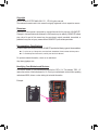
Identifying Your Motherboard Revision
The revision number on your motherboard looks like this: "REV: X.X." For example, "REV: 1.0"
means the revision of the motherboard is 1.0. Check your motherboard revision before updating
motherboard BIOS, drivers, or when looking for technical information.
Example:

- 4 -
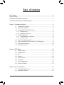
Table of Contents
Box Contents ...................................................................................................................6
Optional Items .................................................................................................................6
G1.Assassin 2 Motherboard Layout ................................................................................7
G1.Assassin 2 Motherboard Block Diagram ...................................................................8
Chapter 1 Hardware Installation .....................................................................................9
1-1 Installation Precautions ................................................................................... 9
1-2 Product Specications ................................................................................... 10
1-3 Installing the CPU and CPU Cooler............................................................... 13
1-3-1 Installing the CPU ..................................................................................................13
1-3-2 Installing the CPU Cooler ......................................................................................15
1-4 Installing the Memory .................................................................................... 16
1-4-1 4 Channel Memory Conguration.........................................................................16
1-4-2 Installing a Memory ...............................................................................................17
1-5 Installing an Expansion Card ......................................................................... 18
1-6 Setting up AMD CrossFireX
™
/NVIDIA SLI Conguration .............................. 19
1-7 Back Panel Connectors ................................................................................. 20
1-8 Internal Connectors ....................................................................................... 22
Chapter 2 BIOS Setup ..................................................................................................31
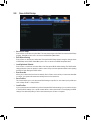
2-1 Startup Screen ............................................................................................... 32
2-2 The Main Menu .............................................................................................. 33
2-3 M.I.T. .............................................................................................................. 35
2-4 System ........................................................................................................... 48
2-5 BIOS Features ............................................................................................... 49
2-6 Peripherals ..................................................................................................... 51
2-7 Power Management ....................................................................................... 53
2-8 Save & Exit Setup .......................................................................................... 55
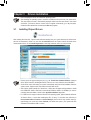
Chapter 3 Drivers Installation .......................................................................................57
3-1 Installing Chipset Drivers ............................................................................... 57
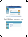
3-2 Application Software ...................................................................................... 58

- 5 -
3-3 Technical Manuals ......................................................................................... 58
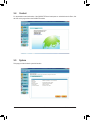
3-4 Contact........................................................................................................... 59
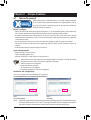
3-5 System ........................................................................................................... 59
3-6 Download Center ........................................................................................... 60
3-7 New Utilities ................................................................................................... 60
Chapter 4 Unique Features ...........................................................................................61
4-1 Xpress Recovery2 .......................................................................................... 61
4-2 BIOS Update Utilities ..................................................................................... 64
4-2-1 Updating the BIOS with the Q-Flash Utility .......................................................... 64
4-2-2 Updating the BIOS with the @BIOS Utility ............................................................67
4-3 EasyTune 6 .................................................................................................... 68
4-4 Q-Share ......................................................................................................... 69
4-5 Smart 6
™
....................................................................................................... 70
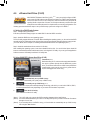
4-6 eXtreme Hard Drive (X.H.D) .......................................................................... 74
4-7 Cloud OC ....................................................................................................... 75
4-8 TouchBIOS..................................................................................................... 76
Chapter 5 Appendix ......................................................................................................77
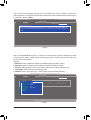
5-1 Conguring SATA Hard Drive(s) .................................................................... 77
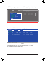
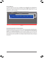
5-1-1 Conguring Intel X79 SATA Controllers ................................................................77
5-1-2 Conguring Marvell 88SE9172 SATA Controllers ................................................ 83
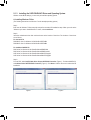
5-1-3 Installing the SATA RAID/AHCI Driver and Operating System ............................ 89
5-2 Bigfoot Killer Network Manager ..................................................................... 96
5-3 Conguring Audio Input and Output .............................................................. 98
5-3-1 Conguring 2/4/5.1/7.1-Channel Audio ................................................................. 98
5-3-2 Conguring S/PDIF Out ........................................................................................ 99
5-3-3 Creative Software Suite ...................................................................................... 100
5-3-4 Enabling Dolby Digital Live/DTS Connect Encoding ..........................................101
5-3-5 Conguring Audio Recording ..............................................................................103
5-4 Troubleshooting ........................................................................................... 104
5-4-1 Frequently Asked Questions ...............................................................................104
5-4-2 Troubleshooting Procedure .................................................................................105
5-4-3 Regulatory Statements ........................................................................................107

- 6 -
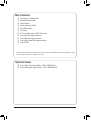
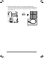
Box Contents
G1.Assassin 2
5
motherboard
Motherboard driver disk
5
User's Manual
5
Quick Installation Guide
5
Four SATA cables
5
I/O Shield
5
3.5" Front Panel with 2 USB 3.0/2.0 ports
5
One 2-Way SLI bridge connector
5
One 3-Way SLI bridge connector
5
One 2-Way CrossFireX bridge connector
5
One GC-WIFI
5
Optional Items
2-port USB 2.0 bracket (Part No. 12CR1-1UB030-5*R)
2-port SATA power cable (Part No. 12CF1-2SERPW-0*R)
The box contents above are for reference only and the actual items shall depend on the product package you obtain.
The box contents are subject to change without notice.

- 7 -
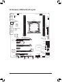
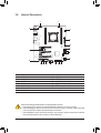
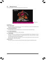
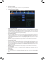
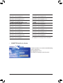
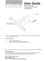
G1.Assassin 2 Motherboard Layout
KB_MS_USB
CPU_FAN
ATX_12V_2X
ATX
F_AUDIO
AUDIO
B_BIOS
PCIEX8
DDR3_2
DDR3_4
DDR3_1
DDR3_3
BAT
F_PANEL
Intel
®
X79
CLR_CMOS
FAN1
M_BIOS
PCIEX1_1
PCIEX16_1
SPDIF_O
F_USB1
LGA2011
G1.Assassin 2
HS
R_USB30
USB_ESATA2
USB_LAN
PCI
F_USB30
PCIEX1_2
iTE
IT8728
TPM
F_USB2
F_USB3
Marvell
88SE9172
USB_ESATA1
FAN4
Fresco
FL1009
CREATIVE
CA20K2
Marvell 88E1118R
Bigfoot Killer
E2100
PCIEX16_2
FAN2
FAN3
GSATA3
7
6
SATA2
SATA3
1
0
Fresco
FL1009
3
2
SATA2
5
4
System2 Temp.
sensor
System3 Temp.
sensor
System1 Temp.
sensor
Marvell
88SE9172

- 8 -
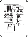
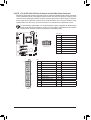
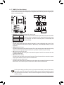
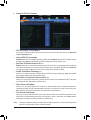
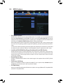
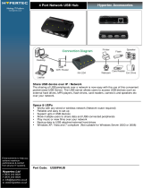
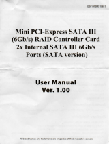
G1.Assassin 2 Motherboard Block Diagram
PS/2 KB/Mouse
LGA2011
CPU
CPU CLK+/- (100 MHz)
2 SATA 6Gb/s
Dual BIOS
14 USB 2.0/1.1
(Note)
DDR3 2133/1866/1600/1333/1066 MHz
4 Channel Memory
LPC Bus
Intel
®
X79
x1
2 USB 3.0/2.0
Fresco
FL1009
iTE
IT8728
x1
2 USB 3.0/2.0
PCI Express Bus
PCI Express Bus
PCIe CLK
(100 MHz)
2 PCI Express x1
x1
2 SATA 6Gb/s
x1
Marvell
88SE9172
x1
DMI 2.0
4 SATA 3Gb/s
Fresco
FL1009
PCIe CLK
(100 MHz)
2 PCI Express x16
x16 x16
1 PCI Express x8
x8
PCI Express Bus
x1
LAN
RJ45
Marvell
88E1118R phy
BigFoot Killer E2100
Center/Subwoofer Speaker Out
Line Out
MIC
Line In
S/PDIF Out
Side Speaker Out
Surround Speaker Out
CREATIVE
CA20K2
x1
PCI Bus
1 PCI
PCI CLK
(33 MHz)
PCI Express Bus
2 SATA 6Gb/s
x1
Marvell
88SE9172
(Note) Two share the same ports with eSATA.

- 9 - Hardware Installation
1-1 Installation Precautions
The motherboard contains numerous delicate electronic circuits and components which can become
damaged as a result of electrostatic discharge (ESD). Prior to installation, carefully read the user's
manual and follow these procedures:
Prior to installation, make sure the chassis is suitable for the motherboard. •
Prior to installation, do not remove or break motherboard S/N (Serial Number) sticker or warranty •
sticker provided by your dealer. These stickers are required for warranty validation.
Always remove the AC power by unplugging the power cord from the power outlet before •
installing or removing the motherboard or other hardware components.
When connecting hardware components to the internal connectors on the motherboard, make •
sure they are connected tightly and securely.
When handling the motherboard, avoid touching any metal leads or connectors. •
It is best to wear an electrostatic discharge (ESD) wrist strap when handling electronic com- •
ponents such as a motherboard, CPU or memory. If you do not have an ESD wrist strap, keep
your hands dry and rst touch a metal object to eliminate static electricity.
Prior to installing the motherboard, please have it on top of an antistatic pad or within an •
electrostatic shielding container.
Before unplugging the power supply cable from the motherboard, make sure the power supply •
has been turned off.
Before turning on the power, make sure the power supply voltage has been set according to •
the local voltage standard.
Before using the product, please verify that all cables and power connectors of your hardware •
components are connected.
To prevent damage to the motherboard, do not allow screws to come in contact with the •
motherboard circuit or its components.
Make sure there are no leftover screws or metal components placed on the motherboard or •
within the computer casing.
Do not place the computer system on an uneven surface •
.
Do not place the computer system in a high-temperature environment. •
Turning on the computer power during the installation process can lead to damage to system •
components as well as physical harm to the user.
If you are uncertain about any installation steps or have a problem related to the use of the •
product, please consult a certied computer technician.
Chapter 1 Hardware Installation

Hardware Installation - 10 -
1-2 Product Specications
CPU Support for Intel
®
Core
™
i7 processors in the LGA2011 package
(Go to GIGABYTE's website for the latest CPU support list.)
L3 cache varies with CPU
Chipset Intel
®
X79 Express Chipset
Memory 4 x 1.5V DDR3 DIMM sockets supporting up to 32 GB of system memory
* Due to Windows 32-bit operating system limitation, when more than 4 GB of physical
memory is installed, the actual memory size displayed will be less than 4 GB.
4 channel memory architecture
Support for DDR3 2133/1866/1600/1333/1066 MHz memory modules
Support for non-ECC memory modules
Support for Extreme Memory Prole (XMP) memory modules
(Go to GIGABYTE's website for the latest supported memory speeds and memory
modules.)
Audio 1 x Creative CA20K2 chip
Support for Dolby
®
Digital Live and DTS
™
Connect
Support for X-Fi Xtreme Fidelity
®
and EAX
®
Advanced HD
™
5.0 technologies
High Denition Audio
2/4/5.1/7.1-channel
Support for S/PDIF Out
LAN 1 x Bigfoot Killer E2100 chip (10/100/1000 Mbit)
1 x Marvell 88E1118R phy
Expansion Slots 2 x PCI Express x16 slots, running at x16 (PCIEX16_1/PCIEX16_2)
* For optimum performance, if only one PCI Express graphics card is to be installed, be
sure to install it in the PCIEX16_1 slot; if you are installing two PCI Express graphics
cards, it is recommended that you install them in the PCIEX16_1 and PCIEX16_2
slots.
1 x PCI Express x16 slot, running at x8 (PCIEX8)
(All PCI Express x16 slots conform to PCI Express 3.0 standard.)
2 x PCI Express x1 slots
(All PCI Express x1 slots conform to PCI Express 2.0 standard.)
1 x PCI slot
Multi-Graphics
Technology
Support for 3-Way/2-Way AMD CrossFireX
™
/ NVIDIA SLI technology
* The PCIEX16_1/PCIEX16_2 slots operate at up to x8 mode when 3-Way AMD
CrossFireX
™
/NVIDIA SLI is enabled.
Storage Interface Chipset:
- 2 x SATA 6Gb/s connectors (SATA3 0/SATA3 1) supporting up to 2 SATA
6Gb/s devices
- 4 x SATA 3Gb/s connectors (SATA2 2~SATA2 5) supporting up to 4 SATA
3Gb/s devices
- Support for RAID 0, RAID 1, RAID 5, and RAID 10
* When a RAID set is built across the SATA 6Gb/s and SATA 3Gb/s channels, the
system performance of the RAID set may vary depending on the devices being
connected.

- 11 - Hardware Installation
Storage Interface 2 x Marvell 88SE9172 chips:
- 2 x SATA 6Gb/s connectors (GSATA3 6/GSATA3 7) supporting up to 2 SATA
6Gb/s devices
- 2 x eSATA 6Gb/s connectors (eSATA/USB Combo) on the back panel
supporting up to 2 SATA 6Gb/s devices
- Support for RAID 0 and RAID 1
USB Chipset:
- Up to 14 USB 2.0/1.1 ports (8 ports on the back panel, including 2 eSATA/
USB Combo, 6 ports available through the internal USB headers)
2 x Fresco FL1009 chips:
- Up to 4 USB 3.0/2.0 ports (2 ports on the back panel, 2 ports available through
the internal USB header)
Internal
Connectors
1 x 24-pin ATX main power connector
1 x 8-pin ATX 12V power connector
4 x SATA 6Gb/s connectors
4 x SATA 3Gb/s connectors
1 x CPU fan header
4 x fan headers
1 x front panel header
1 x front panel audio header
1 x S/PDIF Out header
3 x USB 2.0/1.1 headers
1 x USB 3.0/2.0 header
1 x Clear CMOS jumper
1 x Trusted Platform Module (TPM) header
Back Panel
Connectors
1 x PS/2 keyboard/mouse port
1 x CPU overclocking button
1 x BIOS switch button
1 x Clear CMOS button
1 x optical S/PDIF Out connector
6 x USB 2.0/1.1 ports
2 x USB 3.0/2.0 ports
2 x eSATA/USB Combo connectors
1 x RJ-45 port
5 x audio jacks (Center/Subwoofer Speaker Out, Rear Speaker Out, Side Speaker
Out, Line In/Mic In, Line Out)
I/O Controller iTE IT8728 chip

Hardware Installation - 12 -
Hardware
Monitor
System voltage detection
CPU/System temperature detection
CPU/System fan speed detection
CPU overheating warning
CPU/System fan fail warning
CPU/System fan speed control
* Whether the CPU/system fan speed control function is supported will depend on the
CPU/system cooler you install.
BIOS 2 x 64 Mbit ash
Use of licensed AMI EFI BIOS
Support for DualBIOS
™
PnP 1.0a, DMI 2.0, SM BIOS 2.6, ACPI 2.0a
Unique Features Support for @BIOS
Support for Q-Flash
Support for Xpress BIOS Rescue
Support for Download Center
Support for Xpress Install
Support for Xpress Recovery2
Support for EasyTune
* Available functions in EasyTune may differ by motherboard model.
Support for Smart 6
™
Support for eXtreme Hard Drive (X.H.D)
Support for ON/OFF Charge
Support for Cloud OC
Support for 3TB+ Unlock
Support for TouchBIOS
Support for Q-Share
Bundled
Software
Norton Internet Security (OEM version)
Operating
System
Support for Microsoft
®
Windows 7/Vista/XP
Form Factor E-ATX Form Factor; 30.5cm x 26.4cm
* GIGABYTE reserves the right to make any changes to the product specications and product-related information
without prior notice.

- 13 - Hardware Installation
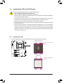
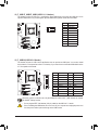
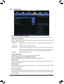
1-3 Installing the CPU and CPU Cooler
1-3-1 Installing the CPU
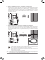
A. Locate the alignment keys on the motherboard CPU socket and the notches on the CPU.
Read the following guidelines before you begin to install the CPU:
Make sure that the motherboard supports the CPU. •
(Go to GIGABYTE's website for the latest CPU support list.)
Always turn off the computer and unplug the power cord from the power outlet before installing the •
CPU to prevent hardware damage.
Locate the pin one of the CPU. The CPU cannot be inserted if oriented incorrectly. (Or you may •
locate the notches on both sides of the CPU and alignment keys on the CPU socket.)
Apply an even and thin layer of thermal grease on the surface of the CPU. •
Do not turn on the computer if the CPU cooler is not installed, otherwise overheating and damage •
of the CPU may occur.
Set the CPU host frequency in accordance with the CPU specications. It is not recommended •
that the system bus frequency be set beyond hardware specications since it does not meet the
standard requirements for the peripherals. If you wish to set the frequency beyond the standard
specications, please do so according to your hardware specications including the CPU, graphics
card, memory, hard drive, etc.
Alignment Key
Alignment Key
LGA2011 CPU Socket
Pin One Corner of the CPU
Socket
LGA2011 CPU
Triangle Pin One Marking on
the CPU
Alignment Key
Alignment Key
Notch
Notch
Notch
Notch

Hardware Installation - 14 -
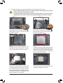
Step 1:
Push the lever closest to the "unlock" marking " "
(below referred as lever A) down and away from
the socket to release it.
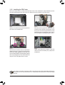
Step 4:
Hold the CPU with your thumb and index ngers. Align
the CPU pin one marking (triangle) with the pin one
corner of the CPU socket (or align the CPU notches
with the socket alignment keys) and carefully insert
the CPU into the socket vertically.
Step 5:
Once the CPU is properly inserted, carefully replace
the load plate. Then secure lever B under its retention
tab. The protective plastic cover may pop off from the
load plate during the process of engaging the lever.
Remove the cover. Save the cover properly and always
replace it when the CPU is not installed.
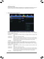
B. Follow the steps below to correctly install the CPU into the motherboard CPU socket.
Before installing the CPU, make sure to turn off the computer and unplug the power cord from •
the power outlet to prevent damage to the CPU.
To protect the socket contacts, do not remove the protective plastic cover unless the CPU is •
inserted into the CPU socket. Save the cover properly and replace it if the CPU is removed.
Step 2:
Push the lever closest to the "lock" marking " "
(below referred as lever B) down and away from
the socket. Then lift the lever.
Lever A
Lever B
Step 3:
Gently press lever A to allow the load plate to rise.
Open the load plate. (Note: DO NOT touch the
socket contacts after the load plate is opened.)
Step 6:
Finally, secure lever A under its retention tab to
complete the installation of the CPU.

- 15 - Hardware Installation
1-3-2 Installing the CPU Cooler
Refer to the steps below to correctly install the CPU cooler on the motherboard. (Actual installation process
may differ depending the CPU cooler to be used. Refer to the user's manual for your CPU cooler.)
Use extreme care when removing the CPU cooler because the thermal grease/tape between the
CPU cooler and CPU may adhere to the CPU. Inadequately removing the CPU cooler may damage
the CPU.
Step 1:
Apply an even and thin layer of thermal grease on
the surface of the installed CPU.
Step 2:
Place the cooler atop the CPU, aligning the four
mounting screws with the mounting holes on the
ILM. (If your cooler has a fan grill which may cause
interference when you tighten the screws, remove
it rst and replace it after tightening the screws.)
Step 3:
Use one hand to hold the cooler and the other to
tighten the screws in a diagonal sequence with a
screw driver. Begin tightening a screw with a few
turns and repeat with the screw diagonally opposite
the one you just tightened. Then do the same to the
other pair. Next, fully tighten the four screws.
Step 4:
Finally, attach the power connector of the CPU
cooler to the CPU fan header (CPU_FAN) on the
motherboard.

Hardware Installation - 16 -
1-4 Installing the Memory
Read the following guidelines before you begin to install the memory:
Make sure that the motherboard supports the memory. It is recommended that memory of the •
same capacity, brand, speed, and chips be used.
(Go to GIGABYTE's website for the latest supported memory speeds and memory modules.)
Always turn off the computer and unplug the power cord from the power outlet before installing the •
memory to prevent hardware damage.
Memory modules have a foolproof design. A memory module can be installed in only one direction. •
If you are unable to insert the memory, switch the direction.
DDR3_1
DDR3_2
DDR3_3
DDR3_4
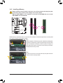
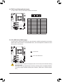
1-4-1 4 Channel Memory Conguration
This motherboard provides four DDR3 memory sockets and supports 4 Channel Technology. After the memory
is installed, the BIOS will automatically detect the specications and capacity of the memory. The four DDR3
memory sockets are divided into four channels and each channel has one memory socket as following:
Channel A: DDR3_4
Channel B: DDR3_2
Channel C: DDR3_1
Channel D: DDR3_3
For optimum performance, when installing one memory module, we recommend that you install it in the DDR3_1
socket. When installing two memory modules, we recommend that you install them in the DDR3_1 and DDR3_2
sockets.
Dual Channel Mode: •
To enable Dual Channel mode, install two memory modules in any two of the four memory sockets.
3 Channel Mode: •
To enable three Channel mode, install three memory modules in any three of the four memory sockets.
4 Channel Mode: •
To enable four Channel mode, install four memory modules in the four memory sockets.

- 17 - Hardware Installation
1-4-2 Installing a Memory
Notch
DDR3 DIMM
A DDR3 memory module has a notch, so it can only t in one direction. Follow the steps below to correctly install
your memory modules in the memory sockets.
Before installing a memory module, make sure to turn off the computer and unplug the power
cord from the power outlet to prevent damage to the memory module.
DDR3 and DDR2 DIMMs are not compatible to each other or DDR DIMMs. Be sure to install
DDR3 DIMMs on this motherboard.
Step 1:
Note the orientation of the memory module. Spread the retaining clips
at both ends of the memory socket. Place the memory module on the
socket. As indicated in the picture on the left, place your ngers on
the top edge of the memory, push down on the memory and insert it
vertically into the memory socket.
Step 2:
The clips at both ends of the socket will snap into place when the
memory module is securely inserted.
DIP
1 2 3 4 5
Z0
DIP
1 2 3 4 5
Z0

Hardware Installation - 18 -
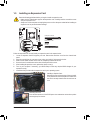
1-5 Installing an Expansion Card
Follow the steps below to correctly install your expansion card in the expansion slot.
Locate an expansion slot that supports your card. Remove the metal slot cover from the chassis back 1.
panel.
Align the card with the slot, and press down on the card until it is fully seated in the slot. 2.
Make sure the metal contacts on the card are completely inserted into the slot.3.
Secure the card’s metal bracket to the chassis back panel with a screw. 4.
After installing all expansion cards, replace the chassis cover(s).5.
Turn on your computer. If necessary, go to BIOS Setup to make any required BIOS changes for your 6.
expansion card(s).
Install the driver provided with the expansion card in your operating system. 7.
Read the following guidelines before you begin to install an expansion card:
Make sure the motherboard supports the expansion card. Carefully read the manual that came •
with your expansion card.
Always turn off the computer and unplug the power cord from the power outlet before installing an •
expansion card to prevent hardware damage.
PCI Express x1 Slot
PCI Express x16 Slot
PCI Slot
Installing a Graphics Card: •
Gently push down on the top edge of the card until it
is fully inserted into the PCI Express slot. Make sure
the card is securely seated in the slot and does not
rock.
Removing the Card: •
Press the latch at the end of the PCI Express slot to release the card and then pull the
card straight up from the slot.

- 19 - Hardware Installation
1-6 Setting up AMD CrossFireX
™
/NVIDIA SLI Conguration
A. System Requirements
The 2-Way CrossFireX and 2-Way SLI technologies currently support Windows 7, Vista, XP operating systems -
The 3-Way CrossFireX and 3-Way SLI technologies currently support Windows 7 and Vista operating systems -
A CrossFireX/SLI-supported motherboard with two/three PCI Express x16 slots and correct driver -
Two/three CrossFireX/SLI-ready graphics cards of identical brand and chip and correct driver -
(Current GPUs that support 3-Way CrossFireX technology include the ATI Radeon HD 3800, HD 4800, HD 5800 series,
and AMD Radeon HD 6800 and HD 6900 series. Current GPUs that support 3-Way SLI technology include the NVIDIA
8800 GTX, 8800 Ultra, 9800 GTX, GTX 260, GTX 280, GTX 470, GTX 480, GTX 570, GTX 580, and GTX 590 series.)
CrossFire -
(Note)
/SLI bridge connectors
A power supply with sufcient power is recommended (Refer to the manual of your graphics cards for the power -
requirement)
B. Connecting the Graphics Cards
Step 1:
Observe the steps in "1-5 Installing an Expansion Card" and install two/three CrossFireX/SLI graphics cards on the PCI
Express x16 slots. (To set up a 2-Way conguration, we recommend installing the graphics cards on the PCIEX16_1 and
PCIEX16_2 slots. )
Step 2:
Insert the CrossFire
(Note )
/SLI bridge connectors in the CrossFireX/SLI gold edge connectors on top of the two/three cards.
Step 3:
Plug the display cable into the graphics card on the PCIEX16_1 slot.
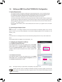
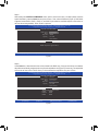
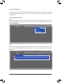
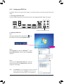
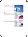
C. Conguring the Graphics Card Driver
C-1. To Enable CrossFireX Function
After installing the graphics card driver in the operating system, go to the Catalyst
Control Center. Browse to Performance\AMD CrossFireX
™
Conguration
and ensure the Enable CrossFireX
™
check box is selected and click Apply.
(Available combination options are dependent on the number of graphics cards
you install.)
Procedure and driver screen for enabling CrossFireX/SLI technology may differ by graphics cards and driver
version. Refer to the manual that came with your graphics cards for more information about enabling CrossFireX/
SLI technology.
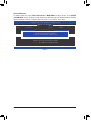
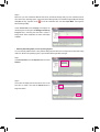
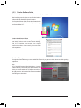
C-2. To Enable SLI Function
After installing the graphics card driver in the operating system, go to the NVIDIA
Control Panel. Browse to the Set SLI and Physx Conguration screen and
ensure Maximize 3D performance is enabled.
(Note) The bridge connector(s) may be needed or not depending on your graphics cards.

Hardware Installation - 20 -
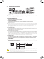
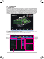
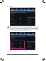
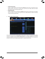
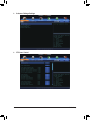
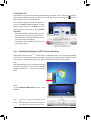
1-7 Back Panel Connectors
USB 2.0/1.1 Port
The USB port supports the USB 2.0/1.1 specication. Use this port for USB devices such as a USB
keyboard/mouse, USB printer, USB ash drive and etc.
PS/2 Keyboard/Mouse Port
Use this port to connect a PS/2 mouse or keyboard.
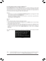
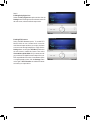
CPU Overclcking Button
Press this button to overclock your CPU. To return to the defaults, press this button again.
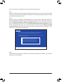
BIOS Switch Button
The button allows users to easily select a different BIOS for boot up or overclocking, helping to reduce BIOS
failure during overclocking. Press the button to switch between the main BIOS and backup BIOS. The green
LED indicates the main BIOS is active and the blue LED indicates the backup BIOS is active.
Clear CMOS Button
Use the clearing CMOS button to clear the CMOS values (e.g. date information and BIOS congurations) and
reset the CMOS values to factory defaults when needed.
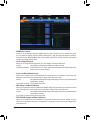
eSATA/USB Combo Connector
This connector supports SATA 6Gb/s and USB 2.0/1.1 specication. Use the port to connect an external
SATA device or a SATA port multiplier. The Marvell 88SE9172 chip supports RAID function. Refer to
Chapter 5, "Conguring SATA Hard Drive(s)," for instructions on conguring a RAID array. Or use this port
for USB devices such as a USB keyboard/mouse, USB printer, USB ash drive and etc.
USB 3.0/2.0 Port
The USB 3.0 port supports the USB 3.0 specication and is compatible to the USB 2.0/1.1 specication.
Use this port for USB devices such as a USB keyboard/mouse, USB printer, USB ash drive and etc.
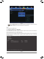
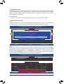
RJ-45 LAN Port
The Gigabit Ethernet LAN port provides Internet connection at up to 1 Gbps data rate. The following
describes the states of the LAN port LEDs.
When removing the cable connected to a back panel connector, rst remove the cable from your •
device and then remove it from the motherboard.
When removing the cable, pull it straight out from the connector. Do not rock it side to side to •
prevent an electrical short inside the cable connector.
O.C.
Link LED
Speed/Activity LED
LAN Port
Link LED:
Speed/Activity LED:
State Description
Orange 10 Mbps data rate
Green +
Orange
100 Mbps data rate
Green 1 Gbps data rate
Blinking Network activity
Off No connection
State Description
On Linked properly
Off No link
Page is loading ...
Page is loading ...
Page is loading ...
Page is loading ...
Page is loading ...
Page is loading ...
Page is loading ...
Page is loading ...
Page is loading ...
Page is loading ...
Page is loading ...
Page is loading ...
Page is loading ...
Page is loading ...
Page is loading ...
Page is loading ...
Page is loading ...
Page is loading ...
Page is loading ...
Page is loading ...
Page is loading ...
Page is loading ...
Page is loading ...
Page is loading ...
Page is loading ...
Page is loading ...
Page is loading ...
Page is loading ...
Page is loading ...
Page is loading ...
Page is loading ...
Page is loading ...
Page is loading ...
Page is loading ...
Page is loading ...
Page is loading ...
Page is loading ...
Page is loading ...
Page is loading ...
Page is loading ...
Page is loading ...
Page is loading ...
Page is loading ...
Page is loading ...
Page is loading ...
Page is loading ...
Page is loading ...
Page is loading ...
Page is loading ...
Page is loading ...
Page is loading ...
Page is loading ...
Page is loading ...
Page is loading ...
Page is loading ...
Page is loading ...
Page is loading ...
Page is loading ...
Page is loading ...
Page is loading ...
Page is loading ...
Page is loading ...
Page is loading ...
Page is loading ...
Page is loading ...
Page is loading ...
Page is loading ...
Page is loading ...
Page is loading ...
Page is loading ...
Page is loading ...
Page is loading ...
Page is loading ...
Page is loading ...
Page is loading ...
Page is loading ...
Page is loading ...
Page is loading ...
Page is loading ...
Page is loading ...
Page is loading ...
Page is loading ...
Page is loading ...
Page is loading ...
Page is loading ...
Page is loading ...
Page is loading ...
Page is loading ...
Page is loading ...
Page is loading ...
Page is loading ...
Page is loading ...
-
 1
1
-
 2
2
-
 3
3
-
 4
4
-
 5
5
-
 6
6
-
 7
7
-
 8
8
-
 9
9
-
 10
10
-
 11
11
-
 12
12
-
 13
13
-
 14
14
-
 15
15
-
 16
16
-
 17
17
-
 18
18
-
 19
19
-
 20
20
-
 21
21
-
 22
22
-
 23
23
-
 24
24
-
 25
25
-
 26
26
-
 27
27
-
 28
28
-
 29
29
-
 30
30
-
 31
31
-
 32
32
-
 33
33
-
 34
34
-
 35
35
-
 36
36
-
 37
37
-
 38
38
-
 39
39
-
 40
40
-
 41
41
-
 42
42
-
 43
43
-
 44
44
-
 45
45
-
 46
46
-
 47
47
-
 48
48
-
 49
49
-
 50
50
-
 51
51
-
 52
52
-
 53
53
-
 54
54
-
 55
55
-
 56
56
-
 57
57
-
 58
58
-
 59
59
-
 60
60
-
 61
61
-
 62
62
-
 63
63
-
 64
64
-
 65
65
-
 66
66
-
 67
67
-
 68
68
-
 69
69
-
 70
70
-
 71
71
-
 72
72
-
 73
73
-
 74
74
-
 75
75
-
 76
76
-
 77
77
-
 78
78
-
 79
79
-
 80
80
-
 81
81
-
 82
82
-
 83
83
-
 84
84
-
 85
85
-
 86
86
-
 87
87
-
 88
88
-
 89
89
-
 90
90
-
 91
91
-
 92
92
-
 93
93
-
 94
94
-
 95
95
-
 96
96
-
 97
97
-
 98
98
-
 99
99
-
 100
100
-
 101
101
-
 102
102
-
 103
103
-
 104
104
-
 105
105
-
 106
106
-
 107
107
-
 108
108
-
 109
109
-
 110
110
-
 111
111
-
 112
112


Gigabyte G1.Assassin 2 (rev. 1.0) User manual
- Category
- Motherboards
- Type
- User manual
Ask a question and I''ll find the answer in the document
Finding information in a document is now easier with AI
Related papers
-
Gigabyte GA-P55-UD3R Owner's manual
-
Gigabyte H610I DDR4 Owner's manual
-
Gigabyte H510M H Owner's manual
-
Gigabyte B660M GAMING AC DDR4 Owner's manual
-
Gigabyte B560I AORUS PRO AX Owner's manual
-
Gigabyte GA-X79-UD3 Owner's manual
-
Gigabyte GA-Z68XP-D3 Owner's manual
-
Gigabyte GA-Z97MX-GAMING 5 User manual
-
Gigabyte GA-Z77MX-D3H TH User manual
-
Gigabyte GA-HA65M-D2H-B3 Owner's manual
Other documents
-
 Hypertec USBIPHUB Datasheet
-
Teleco RETROCAMERA TRCL CMOS User manual
-
DeLOCK 89271 Datasheet
-
EXSYS EX-3505 User manual
-
 Addonics Technologies AD2SA6GPX1 User manual
-
Sabrent EC-UEIS7 User manual
-
-
-
Sitecom XC-043 Datasheet
-
 IO CREST SI-MPE40095 User guide


