Page is loading ...

HGMIG 251A
OWNER’S MANUAL
WARNING:
Read carefully and understand all ASSEMBLY AND OPERATION
INSTRUCTIONS before operating. Failure to fo llow the safety rules and other
basic safety precautions may result in serious personal injury.
Revision 2018-1-31

Safety Rules
“Danger” indicates an imminently hazardous situation which, if not avoided,
will result in death or serious injury.
“Warning!” indicates a possible hazardous situation which, if not avoided, could
result in death or serious injury. The possible hazards are explained in the text.
“Caution” indicates a possible hazardous situation which, if not avoided, may
result in slight or moderate injury.
“Note!” indicates a situation which implies a risk of impaired welding result
and damage to the equipment.
“Important!”indicates practical tips and other useful special-message.
It is no signal word for a harmful or dangerous situation.
Utilisation for intended purpose only.The machine may only be used for jobs
as defined by the “Intended purpose”.
Utilisation for any other purpose, or in any other manner, shall be deemed to be
“not in accordance with the intended purpose”. The manufacturer shall not be
liable for any damage resulting from such improper use.
Safety signs. All the safety instructions and danger warnings on the
machine must be kept in legible condition, not removed, not be covered,
pasted or painted cover.
Safety inspection.The owner/operator is obliged to perform safety inspection at
regular intervals.
The manufacturer also recommends every 3-6 months for regular maintenance of
power sources.
Electric shock can kill. Touching live parts can cause fatal electric shocks or
severe burns. When the machine is switched on, the electrode and ground circuit is
electrically live, The input power circuit and machine internal circuits are also live
when input is on. In MIG/MAG welding, the wire, drive rollers, wire feed housing and
all metal parts touching the welding wire are electrically live. Incorrectly installed or
improperly grounded equipment can be a danger.
Do not touch live parts of the welding circuit, electrodes and wires with your bare
skin or wet clothing.
The operator must wear dry hole-free insulating welding gloves and body protection
while performs the welding.
Insulate yourself from work and ground using dry insulating protection which can be
covered enough to prevent you full area of physical contact with the work or ground.
Connect the primary input cable according to rules. Disconnect input power or stop
machine before installing or maintenance.
2

Connect the primary input cable according to rules. Disconnect input power
or stop machine before installing or maintenance.
If welding must be performed under electrically hazardous conditions as
follow: in damp locations or wearing wet clothing; on metal structures such as
floors, gratings, or scaffolds; when in cramped positions such as sitting,
kneeling, or lying; or in occasion when there is a high risk of unavoidable or
accidental contact with the work piece or ground. Must use additional safety
precautions: semiautomatic DC constant voltage (wire) welder, DC manual
(Stick) welder and AC welder with reduced open-load voltage.
Any maintenance work must be carried out in a good and safe condition.
Once found, damaged part must be repaired or replaced immediately.
Electric and magnetic fields (EMF) may be dangerous. If electromagnetic
interference is found to be occurring, the operator
is obliged to examine
any possible electromagnetic problems that may occur on
equipment as follow:
- Minas, signal and data-transmission leads
- IT and telecoms equipment
- IT and telecoms equipment
- Wearers of pacemakers
Measures for minimizing or preventing EMC problems:
-Mains supply
If electromagnetic interference still occurs, despite the fact that the mains
connection in accordance with the regulations, take additional measures
-Welding cables
Keep these as short as possible.
Connect the work cable to the work piece as close as possible to the area
being welded.
Lay them well away from other cables.
Do not place your body between your electrode and work cables.
-Equipotential bonding
-Workpiece grounding (earthing)
-Shielding
Shield the entire welding equipment and other equipment nearby.
ARC rays can burn. Visible and invisible rays from welding processes can
burn eyes and skin.
Always wear an approved welding helmet or suitable clothing made from
durable flame-resistant material (leather, heavy cotton, or wool) to protect
your eyes and skin from arc rays and sparks when welding or watching.
Always use protective screens or barriers to protect other nearby personnel
with suitable, non-flammable screening and/or warn them not to watch the
arc nor expose themselves to the arc rays or to hot spatter or material.
Fumes and gases can be dangerous. Welding may produce fumes
and gases, breathing these fumes and gases can be hazardous to
your health.
3

When welding, keep your head out of the fume. If inside, ventilate the area at
the arc to keep fumes and gases away from the breathing zone. If ventilation
is not good, wear an approved air-supplied respirator.
Work in a confined space only if it is well ventilated, or while wearing an air-
supplied respirator.
Welding fumes and gases can displace air and lower the oxygen level
causing injury or death. Always use enough ventilation, especially in
confined areas, to insure breathing air is safe.
Welding and cutting sparks can cause fire or explosion. When not
welding, make sure the electrode circuit is not touching the work or ground.
Accidental contact can cause sparks, explosion, overheating, or fire. Make
sure the area is safe before doing any welding.
Welding and cutting on closed containers, such as tanks, drums, or
containers, can cause them to blow up. Make sure proper steps have been
taken.
When pressure gas is used at the work site, special precautions are required
to prevent hazardous situations.
Connect work cable to the work as close to the welding zone as practical to
prevent welding current from passing too long and creating fire hazards or
overheat.
Wear oil-free protective garments such as leather gloves, heavy shirt,
cuffless trousers, high shoes, and a cap. Wear ear plugs when welding out of
position or in confined places. Always wear safety glasses with side shields
when in a welding area.
Be attention that welding sparks and hot materials from welding can easily go
through small cracks and openings to adjacent areas and start a fire. Remove
fire hazardous from the welding area, if not possible, cover them thoroughly.
Do not weld where flying sparks can strike flammable material and where the
atmosphere may contain flammable dust, gas, or liquid vapors (such as
gasoline).
Protect yourself and others from flying sparks and hot metal. Remove any
combustibles from operator before perform any welding.
Keep a fire extinguisher readily available.
Empty containers, tanks, drums, or pipes which have combustibles before
perform welding.
Remove stick electrode from electrode holder or cut off welding wire at
contact tip when not in use.
Apply correct fuses or circuit breakers. Do not oversize or bypass them.
Cylinder can explode if damaged. Compressed cylinders are high pressure
vessels. Improper operation can cause cylinders explosion. Since gas
cylinders are normally part of the welding process, be careful to treat them.
4

Cylinders should be located away from areas where they may be struck or
subjected to physical damage. Use proper equipment, procedures, and
sufficient number of persons to lift and move cylinders.
Always keep cylinders in an upright position by securing to a stationary
support or cylinder rack to prevent falling over or tipping.
Keep a safe distance from arc welding or cutting operations and any other
source of heat, sparks, or flame.
No touching cylinder by welding electrode, electrode holder or any other
electrically “hot” parts. Do not drape welding cables or welding torches over a
gas cylinder.
Use only correct compressed gas cylinders, regulators, hoses, and fittings
designed for the process used; maintain them and associated parts in good
condition.
Use only compressed gas cylinders containing the correct shielding gas for
the properly operating regulators designed for the gas and pressure used. All
hoses, fittings, etc. should be suitable for the application and maintained in
good condition.
Open the cylinder valve slowly and keep your head and face away from the
cylinder valve outlet.
Valve protection caps should be kept in place over valve expect when the
cylinder is in use or connected for use.
Hot parts can burn. Do not touch hot parts with bare hand or skin.
Ensure equipment is cooled down before performing any work.
If touching hot parts is needed, use proper tools and/or wear heavy, insulated
welding gloves and clothing to prevent burns.
Flying metal or dirt can injure eyes. When welding, chipping, wire
brushing, and grinding can cause sparks and flying metal. It can hurt your
eyes.
Remember wear appropriate safety glasses with side shields when in welding
zone, even under your welding helmet.
Noise can damage hearing. Noise can be from some working equipments or
processes, use approved ear protection to protect ears if noise level is high.
Moving parts can injure. Moving parts such as fans, rotors, and belts can
cause severe harm to your body.
Be careful to your fingers when operating, stay away from pinch points such
as drive rolls.
Keep all doors, panels, covers, and guards closed and securely in place.
Have only qualified persons remove doors, panels, covers, or guards for
servicing and maintenance. Reinstall doors, panels, covers, or guards when
servicing and maintenance is finished and before reconnecting input power.
5

Overuse can cause overheating. Overuse can damage the machine, follow
duty cycle to use the machine.
Reduce current or reduce duty cycle before starting to weld again.
Allow cooling period.
Do not block the airflow to unit.
Static can damage PCB. Always wear wrist straps before touching PCB or
parts. Use proper static-proof bags and package to store or move PCB.
Safety markings. Equipment with CE-markings fulfils the basic requirements
of the Low-Voltage and Electromagnetic Compatibility Guideline (e.g.
relevant product standards according to EN 60 974).
Equipment with CCC markings meets the requirements of implementations
rules for China compulsory certification.
Equipment with CSA -Test Mark meets the requirements made in the
standards for Canada and the USA.
6

“Danger” indique une situation dangereuse imminente qui, si elle n'est pas
évitée, entraînera la mort ou des blessures graves.
“Alerte!” Indique une situation dangereuse possible qui, si elle n'est pas
évitée, pourrait entraîner la mort ou des blessures graves. Les risques
possibles sont expliqués dans le texte.
“Attention” indique une situation dangereuse qui, si elle n'est pas évitée,
peut entraîner des blessures légères ou modérées.
“Remarque!” Indique une situation qui implique un risque de perte de
résultat de soudure et d'endommagement de l'équipement.
Utilisation uniquement pour le but prévu. La machine ne peut être utilisée
que pour les travaux définis par «Objet prévu». L'utilisation à d'autres fins, ou
de toute autre manière, est réputée "non conforme à l'objectif prévu". Le
fabricant ne sera pas responsable des dommages résultant d'une utilisation
inappropriée.
Panneaux de sécurité. Toutes les consignes de sécurité et les
avertissements de danger sur la machine doivent être conservés dans un état
lisible, non enlevé, ne pas être recouvert, collé ou peint.
Inspection de sécurité. Le propriétaire / l'opérateur est obligé d'effectuer
une inspection de sécurité à intervalles réguliers. Le fabricant recommande
également tous les 3-6 mois pour la maintenance régulière des sources
d'alimentation.
Le choc électrique peut tuer. Toucher les pièces en direct peut causer des
chocs électriques mortels ou des brûlures graves. Lorsque la machine est
allumée, l'électrode et le circuit de masse sont électriquement en direct. Le
circuit de puissance d'entrée et les circuits internes de la machine sont
également en direct lorsque l'entrée est activée. Dans le soudage MIG /
MAG, le fil, les rouleaux d'entraînement, le boîtier d'alimentation en fil et
toutes les pièces métalliques qui touchent le fil de soudure sont
électriquement en direct. Des équipements incorrectement installés ou mal
branchés peuvent constituer un danger.
Ne touchez pas les parties actives du circuit de soudage, les électrodes et les
fils avec votre peau nue ou vos vêtements humides.
L'opérateur doit porter des gants de soudage isolés sans trous secs et une
protection du corps tout en effectuant le soudage.
Éliminez-vous du travail et du sol en utilisant une protection isolante sèche
qui peut être suffisamment couverte pour vous empêcher de toucher
complètement le contact physique avec le sol ou le sol.
Connectez le câble d'entrée principal selon les règles. Débranchez
l'alimentation d'entrée ou la machine d'arrêt avant l'installation ou la
maintenance.
Les règles de sécurité
7

Si le soudage doit être effectué dans des conditions électriquement
dangereuses comme suit: dans des endroits humides ou portant des
vêtements humides; sur des structures métalliques telles que des planchers,
des grilles ou des échafaudages; quand il se trouve à des positions étroites
telles que assis, agenouillé ou couché; ou en cas de risque élevé de contact
inévitable ou accidentel avec la pièce ou le sol. Doit utiliser des précautions
de sécurité supplémentaires: soudeur de tension constante (fil) semi-
automatique, soudage manuel DC (Stick) et soudeuse à courant alternatif
avec tension de charge réduite.
Tout travail de maintenance doit être effectué dans un état bon et sûr. Une
fois trouvé, la pièce endommagée doit être réparée ou remplacée
immédiatement.
Les champs électriques et magnétiques (EMF) peuvent être dangereux.
Si des perturbations électromagnétiques se produisent, l'opérateur est
obligé d'examiner les éventuels problèmes électromagnétiques pouvant
survenir sur l'équipement comme suit:
- Mines, signaux et transmission de données
- Matériel informatique et télécom
- Appareils de mesure et d'étalonnage
- Porteurs de pacemakers
Mesures pour minimiser ou prévenir les problèmes de compatibilité
électromagnétique:
Alimentation secteur
Si des interférences électromagnétiques se produisent encore, malgré le fait
que la connexion secteur conformément à la réglementation, prendre des
mesures supplémentaires
Câbles de soudure
Gardez ces aussi courts que possible.
Connectez le câble de travail à la pièce de travail le plus près possible de la
zone soudée.
Collez-les bien loin des autres câbles.
Ne placez pas votre corps entre votre électrode et vos câbles de travail.
Collage équipotentiel
Mise à la terre de la pièce (mise à la terre)
Blindage
Boucler l'ensemble de l'équipement de soudage et d'autres équipements à
proximité.
Les rayons ARC peuvent brûler. Les rayons visibles et invisibles des
processus de soudure peuvent brûler les yeux et la peau.
Toujours porter un casque de soudage approuvé ou des vêtements
appropriés en matériau résistant à la flamme durable (cuir, coton lourd ou
laine) pour protéger vos yeux et votre peau des rayons d'arc et des étincelles
lors du soudage ou de l'observation.
Toujours utiliser des écrans de protection ou des barrières pour protéger
d'autres membres du personnel à proximité avec un dépistage approprié et
non inflammable et / ou les avertir de ne pas regarder l'arc, ni se exposer aux
rayons d'arc ou aux spatters ou aux matières chaudes.
Les fumées et les gaz peuvent être dangereux. La soudure peut produire
des fumées et des gaz, la respiration de ces fumées et des gaz peut être
dangereuse pour votre santé.
8

Lors du soudage, retirez la tête de la fumée. Si à l'intérieur, ventiler la zone
à l'arc pour éviter les fumées et les gaz de la zone de respiration. Si la
ventilation n'est pas bonne, portez un respirateur approuvé à l'air.
Travailler dans un espace confiné seulement s'il est bien ventilé, ou en
portant un respirateur fourni par l'air.
Les vapeurs et les gaz de soudure peuvent déplacer l'air et abaisser le
niveau d'oxygène causant des blessures ou la mort. Toujours utiliser une
ventilation suffisante, en particulier dans les zones confinées, pour assurer
l'air respirant est sûr.
Les étincelles de soudure et de coupe peuvent provoquer un incendie
ou une explosion. Lors de la soudure, assurez-vous que le circuit de
l'électrode ne touche pas le travail ou le sol. Un contact accidentel peut
provoquer des étincelles, une explosion, une surchauffe ou un incendie.
Assurez-vous que la zone est sûre avant toute soudure.
La soudure et la découpe sur des conteneurs fermés, tels que des
réservoirs, des bidons ou des conteneurs, peuvent les faire exploser.
Assurez-vous que les étapes appropriées ont été prises.
Lorsque des gaz sous pression sont utilisés sur le chantier, des précautions
particulières sont nécessaires pour prévenir les situations dangereuses.
Connectez le câble de travail au travail aussi près de la zone de soudure
que possible pour éviter que le courant de soudure ne passe trop longtemps
et crée des risques d'incendie ou une surchauffe.
Portez des vêtements de protection sans huile tels que des gants en cuir,
une chemise lourde, un pantalon sans manchette, des chaussures hautes
et un capuchon. Portez des bouchons d'oreille lors du soudage hors
position ou dans des endroits confinés. Toujours porter des lunettes de
sécurité avec des protections latérales dans une zone de soudure.
Soyez attentif à ce que les étincelles de soudage et les matériaux chauds
provenant de la soudure puissent facilement passer par de petites fissures
et des ouvertures dans les zones adjacentes et déclencher un incendie.
Retirez le feu dangereux de la zone de soudure, si possible, les couvrir
complètement. Ne pas souder lorsque les étincelles volantes peuvent
enfoncer des matériaux inflammables et où l'atmosphère peut contenir des
vapeurs inflammables, des gaz ou des liquides (comme de l'essence).
Protégez-vous et les autres d'étincelles volantes et de métal chaud.
Enlevez les combustibles de l'opérateur avant d'effectuer toute soudure.
Gardez un extincteur facilement disponible.
Récipients, réservoirs, bidons ou tuyaux vides qui ont des combustibles
avant de procéder au soudage.
Enlevez l'électrode du porte-électrode ou coupez le fil de soudage à la
pointe de contact lorsqu'il n'est pas utilisé.
Appliquer les fusibles ou les disjoncteurs corrects. Ne les surdimensionnez
pas ou ne les contourne pas.
9

Le cylindre peut exploser s'il est endommagé. Les bouteilles
comprimées sont des récipients à haute pression. Un mauvais
fonctionnement peut provoquer une explosion des cylindres. Étant donné
que les bouteilles de gaz font normalement partie du procédé de soudage,
faites attention de les traiter.
Les cylindres doivent être situés à l'écart des zones où ils peuvent être
frappés ou soumis à des dommages physiques. Utiliser l'équipement
approprié, les procédures et un nombre suffisant de personnes pour
soulever et déplacer des cylindres.
Toujours garder les cylindres dans une position verticale en se fixant sur un
support stationnaire ou un support de cylindre pour éviter de tomber ou de
basculer.
Gardez une distance sûre des opérations de soudage à l'arc ou de coupe et
toute autre source de chaleur, des étincelles ou des flammes.
Pas de cylindre touchant par électrode de soudure, support d'électrode ou
toute autre partie électriquement "chaude". Ne pas draguer des câbles de
soudure ou des torches de soudage sur une bouteille de gaz.
Utiliser uniquement des bouteilles, des régulateurs, des tuyaux et des
raccords de gaz comprimés conçus pour le procédé utilisé, les maintenir et
les pièces associées en bon état.
Utiliser uniquement des bouteilles de gaz comprimés contenant le bon gaz
de protection pour les régulateurs de fonctionnement appropriés conçus
pour le gaz et la pression utilisés. Tous les tuyaux, raccords, etc. devraient
être adaptés à l'application et maintenus en bon état.
Ouvrez lentement la soupape de la bouteille et gardez votre tête et votre
visage éloignés de la sortie de la soupape du cylindre.
Les capuchons de protection de la soupape doivent être maintenus en
place sur la vanne prévue lorsque le cylindre est utilisé ou connecté.
Les pièces chaudes peuvent brûler. Ne touchez pas les pièces chaudes
avec la main nue ou la peau. Assurez-vous que l'équipement est refroidi
avant d'effectuer tout travail.
Si des pièces chaudes en contact sont nécessaires, utilisez des outils
appropriés et / ou utilisez des gants de soudure lourds et isolés et des
vêtements pour éviter les brûlures.
Le métal volant ou la saleté peut blesser les yeux. Lorsque le soudage,
l'écaillage, le brossage des fils et le broyage peuvent provoquer des
étincelles et du métal volant. Cela peut nuire à vos yeux.
N'oubliez pas de porter des lunettes de sécurité appropriées avec des
boucliers latéraux en zone de soudure, même sous votre casque de
soudure.
Le bruit peut endommager l'audition. Le bruit peut provenir de certains
équipements ou procédés de travail, utiliser une protection auditive
approuvée pour protéger les oreilles si le niveau de bruit est élevé.
Les pièces en mouvement peuvent blesser. Les pièces mobiles telles
que les ventilateurs, les rotors et les ceintures peuvent causer de graves
dommages à votre corps.
.
10

Faites attention à vos doigts lorsque vous utilisez, restez loin des points de
pincement tels que les rouleaux d'entraînement.
Gardez toutes les portes, les panneaux, les couvercles et les gardes
fermés et solidement en place.
N'utilisez que des personnes qualifiées pour enlever les portes, les
panneaux, les couvercles ou les protections pour l'entretien et la
maintenance. Réinstallez les portes, les panneaux, les couvercles ou les
protections lorsque l'entretien et la maintenance sont terminés et avant de
reconnecter la puissance d'entrée.
Une utilisation excessive peut entraîner une surchauffe. Une utilisation
excessive peut endommager la machine, suivre le cycle de service pour
utiliser la machine.
Réduisez le courant ou réduisez le cycle de service avant de recommencer
à souder.
Permettre la période de refroidissement. Ne bloquez pas le débit d'air à
l'unité.
La statique peut endommager les PCB. Toujours porter des poignets
avant de toucher des PCB ou des pièces. Utilisez des sacs et un paquetage
à l'épreuve de la statique pour stocker ou déplacer des PCB.
Marquages de sécurité. L'équipement avec marquage CE répond aux
exigences de base de la directive sur la compatibilité basse tension et
électromagnétique (par exemple, les normes de produit pertinentes selon
EN 60 974).
L'équipement avec les marques CCC répond aux exigences des règles de
mise en œuvre pour la certification obligatoire en Chine.
L'équipement avec CSA -Test Mark répond aux exigences établies dans les
normes pour le Canada et les États-Unis.
11

Please read and save these instructions. Read through this owner’s manual carefully before
using product. Protect yourself and others by observing all safety information, warnings, and
cautions. Failure to comply with instructions could result in personal injury and/or damage to
product or property. Please retain instructions for future reference.
MIG Welder
12
Operating Instructions and Parts Manual HGMIG251A
Description
HGMIG251A is a wheeled mounted
professional DC MIG machine capable
of welding with solid (with shielding
gas) or flux core wire. Power
requirements are 230VAC (220V-
240V), 60HZ/ with a 50 amp time
delayed fuse or circuit breaker.
Featured 12 heat/voltage settings,
infinite wire speed, over load and
thermal protection. For use with or
without shielding gas, designed for
mild steel, stainless steel and
aluminum welding in construction,
automotive repair, farming and light
industrial. Welds mild steel between
24 gauges to 0.3inch (8mm) in a single
pass.
Unpacking
1.1 Remove cartons, bags or Styrofoam containing the welder and accessories.
1.2 Check the contents with the packing list below.
ITEM
QTY.
MIG Welder
1 unit
MIG torch
1pc
Ground cable/clamp
1pc
Gas hose
1pc
Gas regulator
1 pc
Operator’s Manual
1set
‘L’ Shaped hex wrench
1 pc
Wire roller0.023/0.030, 0.035/0.040
I pc/unit
Contact tip 0.030
,
0.035
,
0.040
I pc/unit

MIG WELDER
CROSS FIRE
13
Operating Instructions and Parts Manual
HGMIG251A
Specifications
DESCRIPTION
SPECIFICATIONS
Power supply
1ph-230V-60HZ
No-load voltage
43V
Output Range
30A/15.5V-250A/25V
Duty cycle
30%
Suggested wire
MIG and Flux core wire
Wire Diameter
.023”,.030, .035, .040”
Dimension (L x W x H) in
37.4*17.7*28.3
Weight
84
.
5KG
Power
Switch
Select
Switch
Spot
welding
Wire feed
regulator
Power
indicator
Thermal
overload
indicator
Voltage
control
Cathode
output
Anode
output
Welding
Gun plug
Control plug

MIG WELDER
CROSS FIRE
14
Operating Instructions and Parts Manual
HGMIG251A
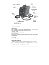
Power Switch
In the “0” position no power is being supplied to the MIG gun. In the “1” position
power is supplied to the main transformer and control circuit
Select Switch
You can select use pull Wire welding torch or Push wire welding torch
Spot Welding
Open the switch can reach 1 ~ 15 second’s adjustable welding time. Namely
setting the torch switch time when the time is over it will stop working.
Thermal overload indicator
When overload using the machine’s internal temperature will rise soon. When the
indicator light the machine will be in thermal protection, you should stop using
and let it rest for 20 minutes before use
Power indicator
The power indicator light meanings the machine has worked.
Voltage control
Adjust the right voltage to achieve the best effect of welding. CAUTION: No
adjust is allowed when welding.
Wire feed regulator
Used to adjust the speed of the wire feeder by adjusting welding current
Cathode output/Anode output
General solid wire welding work piece connect to Cathode and MIG gun connect
to Anode. General Flux Core welding work piece connect to Anode and MIG gun
connect Cathode.
Control plug
Used to control the working state of the machine by connecting plug torch..
Welding Gun plug
Used for connecting welding torch with the gas, electricity, and the output of the
wire.
The power cord connects the welder to the 230 /240volt power supply. Plug the
50 amp plug into 230 volt/50Hz 240 volt/60Hz amp receptacles to supply power
to the welder.

MIG WELDER
CROSS FIRE
15
Operating Instructions and Parts Manual
HGMIG251A
Wiring Diagrams

MIG WELDER
CROSS FIRE
16
Operating Instructions and Parts Manual
HGMIG251A
Assembly
1.Tools required for assembly: Hexagon wrench (M4).
2. MIG gun/torch and Ground Cable/Clamp assembly
3. Retaining groove insert into the Welding Gun plug. Trigger leads insert into the Control
plug. So far we have already installed the MIG torch.
4. Ground cable lead insert into the Cathode output or Anode output.
See following images for reference
5. The terminals next to the positive (“+”) and negative (”-”) marks are for Quick connector
or ground cable lead depending on polarity requirements. When flux core welding, the
ground cable lead is connected to “+” and the Quick connector is connected to “-“as show
in below illustration. When MIG (solid wire) welding, reverse the connection.
Quick
connector
MIG gun
connection
Trigger leads
Retaining
groove
Ground
Clamp

MIG WELDER
CROSS FIRE
17
Operating Instructions and Parts Manual
HGMIG251A
Installation
Provide the necessary steps for correct installation of the product. Include any illustrations or wiring
diagrams that would assist or clarify procedures. Consider the following when preparing your
instructions:
1. Power requirement
AC single phase 230v (220-240V), 60HZ with a 50amp time delayed fuse or circuit breaker
is required. DO NOT OPERATE THIS UNIT IF THE ACTUAL power source voltage is less
than 220 volts ac or greater than 240volts ac.
• High voltage danger from power source! Consult a qualified electrician for proper
installation of receptacle. This welder must be grounded while in use to protect the operator
from electrical shock.
• Do not remove grounding prong or alter the plug in any way. Do not use any adapters
between the welder’s power cord and the power source receptacle. Make sure the POWER
switch is OFF when connecting your welder’s power cord to a properly grounded 230Vac,
60Hz, single phase, 50 amp power source.
2. Extension cord
It is strongly recommended that an extension cord should not be used because of the
voltage drop it produces. This drop in voltage can affect the performance of the welder. If
you need to use an extension cord it must be a #10 gauge cord or larger. Do not use an
extension cord over 25 ft. in length.
3. Install the Drive Roller
Before installing any welding wire into the unit, the proper sized groove must be
placed into position on the wire drive mechanism. Adjust the drive roller
according to the following steps; see following picture
steps; see following picture of the wire feed mechanism:
Guide
Wire
Wire
Roller
Drive tension
arm
Strut
Wing nut

MIG WELDER
CROSS FIRE
18
Operating Instructions and Parts Manual
HGMIG251A
3.1. Open the door to the welder drive compartment.
3.2. Push the strut down and let the drive tension arm away from the Drive Roller.
See following images for reference
3.3. If there is wire already installed in the welder, roll it back onto the wire spool
by hand-turning the spool counterclockwise. Be careful not to allow the wire to
come out of the rear end of the inlet guide tube without holding onto it or it will
unspool itself. Put the end of the wire into the hole on the outside edge of the
wire spool and bend it over to hold the wire in place. Remove the spool of wire
from the spool hub by removing the drive tensioning wing nut and hardware.
3.4. Removal of drive roller.
Loosen by turning milled screw counter-clockwise; Pull the Drive Roller off of the
Drive Roller Shaft
See following images for reference
3.5 Based on the wire diameter select the correct groove using the following
table:
Wire Diameter
Roller Groove
Contact tip
0.030 inch
0.030 inch
0.030 inch
0.035 inch
0.035 inch
0.035 inch
0.040 inch
0.040 inch
0.040 inch
The drive roller has two wire size grooves. When installing the drive roller, the
number stamped on the drive roller for the wire size you are using should face in.
This identifies the inside groove the wire will line up with. Assemble the drive
roller onto the drive roller shaft and use the “L” shaped hex wrench to tighten
(turn clockwise) it in place.

MIG WELDER
CROSS FIRE
19
Operating Instructions and Parts Manual
HGMIG251A
3.6 After you select the Drive Roller, we installed it: insert the Drive Roller into
the Drive Roller Shaft and then use milled screw locking the Drive Roller. See
following images for reference
4. Install the wire
4.1 Selecting the wire
Available wire for this machine
Wire Type
Available
MIG wire
.023 inch
Yes
MIG wire
.030 inch
Yes
Flux core
wire .030 inch
Yes
Flux core
wire .035 inch
Yes
MIG wires available are: mild steel, stainless steel or aluminum solid wire and
must be used with shielding gas.
8 or 11 inch spools are available.
NOTE:
• Burn through will occur if you attempt to weld mild or stainless steel thinner than
24 gauge.
• Remove all rusted wire; if the whole spool is rusty discard it.
4.2 Install the wire

MIG WELDER
CROSS FIRE
20
Operating Instructions and Parts Manual
HGMIG251A
Electric shock can kill! Always turn the POWER switch OFF and unplug the
power cord from the AC power source before installing wire.
NOTE:
• Before installing, make sure that you have removed any old wire from the torch
and cable assembly. This will help to prevent the possibility of the wire jamming
inside the gun Liner.
• Be careful when removing the welding nozzle. The contact tip on this welder is
live when the gun trigger is pulled. Make certain POWER is turned OFF.
4.2.1 Remove the nozzle and contact tip from the end of the gun assembly. See
following images for reference
4.2.2 Make sure the proper groove on the drive roller is in place for the wire
installed. If not, change the drive roller as described above.
4.2.3 Remove the packaging from the spool of wire and then identify the leading
end of the wire secured in a hole on the edge of the spool. DO NOT UNHOOK IT
AT THIS TIME.
4.2.4 Place the spool on the spool hub with the wire coming off the bottom of the
spool. The bottom of the spool aligns with inlet to the drive system for smooth
flow of the wire. The total length of wire is about 8 inch. See following figure.
4.2.5 Both 8 and 11 inch spools can be used, please see the following figure
about the installation onto the spool hubs: The adjustment knob is designed to
adjust the pressure tension of the wire spool.
11’ spool
Damping
screws
/