2
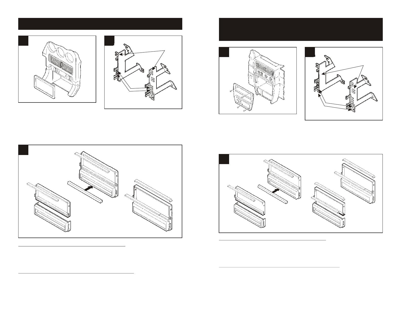
Disconnect the negative battery terminal to
prevent an accidental short circuit. Using a
panel removal tool, pry out on the radio trim
bezel and remove. Remove (4) screws
securing the factory head unit and
disconnect the wiring.
1
DODGE Stealth 1991-96 / MITSUBISHI 3000GT 1991-98
2
3
"E"
"E"
"E"
DASH TRIM BEZELS WITH A DIVIDED RADIO OPENING: If keeping the factory pocket is
NOT desired, cut and remove the upper rib from the radio openingand snap the Filler Bar
onto the bottom of the Radio Housing. (see Fig. A). If keeping the factory pocket is desired,
cut and remove the upper rib from the radio opening and the bottom portion of the Radio
Housing. (see Fig. B). Skip to the Installation Instructions for ALL VEHICLES on Page #12.
DASH TRIM BEZELS WITH AN UNDIVIDED RADIO OPENING: Cut and remove the lower
rib from the radio opening and the top portion of the Radio Housing. (see Fig. C). Skip to the
Installation Instructions for ALL VEHICLES on Page #12.
Fig. A
Fig. B
Fig. C
Cut and remove mounting tabs "A" and "B"
on the Radio Housing. Cut and remove all
mounting tabs on Bracket Set #2 EXCEPT
tabs "E". The mounting tabs can be
identified by the stamped letter on the back
of each tab.
Disconnect the negative battery terminal to
prevent an accidental short circuit. Remove (2)
screws from the top edge of the dash trim bezel.
Remove the ashtray and (2) screws exposed.
Unclip the dash trim bezel and disconnect the
cigarette lighter wiring. Remove (4) Phillips
screws securing the factory head unit and
disconnect the wiring.
1 2
EAGLE Summit (wg) 1992-96 / MITSUBISHI Expo 1992-95
PLYMOUTH Colt Vista 1992-94
"F"
"F"
"F"
3
DASH TRIM BEZELS WITH A DIVIDED RADIO OPENING: If keeping the factory pocket is
NOT desired, cut and remove the upper rib from the radio openingand snap the Filler Bar
onto the bottom of the Radio Housing. (see Fig. A). If keeping the factory pocket is desired,
cut and remove the upper rib from the radio opening and the bottom portion of the Radio
Housing. (see Fig. B). Skip to the Installation Instructions for ALL VEHICLES on Page #12.
DASH TRIM BEZELS WITH AN UNDIVIDED RADIO OPENING: If keeping the factory
pocket is NOT desired, cut and remove the lower rib from the radio opening and the top portion
of the Radio Housing. (see Fig. C). If keeping the factory pocket is desired, cut and remove
the lower rib from the radio opening, the top portion of the Radio Housing and the bottom
portion of the Housing. (see Fig. D). Skip to the Installation Instructions for ALL VEHICLES on
Page #12.
Fig. A
Fig. B
Fig. C
Fig. D
Cut and remove mounting tabs "A" and "B"
on the Radio Housing. Cut and remove all
mounting tabs on Bracket Set #2 EXCEPT
tabs "F". The mounting tabs can be
identified by the stamped letter on the back
of each tab.
3


