PC CHIPS P17G/1333 (V1.0A) User guide
- Category
- Motherboards
- Type
- User guide

i
Motherboard User’s Guide
This publication, including photographs, illustrations and software, is under the
protection of international copyright laws, with all rights reserved. Neither this
user’s guide, nor any of the material contained herein, may be reproduced without
the express written consent of the manufacturer.
The information in this document is subject to change without notice. The manu-
facturer makes no representations or warranties with respect to the contents hereof
and specifically disclaims any implied warranties of merchantability or fitness for
any particular purpose. Further, the manufacturer reserves the right to revise this
publication and to make changes from time to time in the content hereof without
obligation of the manufacturer to notify any person of such revision or changes.
Trademarks
IBM, VGA, and PS/2 are registered trademarks of International Business Ma-
chines.
Intel, Pentium/II/III, Pentium 4, Celeron and MMX are registered trademarks of
Intel Corporation.
Microsoft, MS-DOS and Windows 98/ME/NT/2000/XP are registered trademarks
of Microsoft Corporation.
AMI is a trademark of American Megatrends Inc.
It has been acknowledged that other brands or product names in this manual are
trademarks or the properties of their respective owners.
Static Electricity Precautions
1. Don’t take this motherboard and components out of their original static-
proof package until you are ready to install them.
2. While installing, please wear a grounded wrist strap if possible. If you
don’t have a wrist strap, discharge static electricity by touching the bare
metal of the system chassis.
3. Carefully hold this motherboard by its edges. Do not touch those compo-
nents unless it is absolutely necessary. Put this motherboard on the top of
static-protection package with component side facing up while installing.
Pre-Installation Inspection
1. Inspect this motherboard whether there are any damages to components
and connectors on the board.
2. If you suspect this motherboard has been damaged, do not connect power
to the system. Contact your motherboard vendor about those damages.
Copyright © 2007
All Rights Reserved
P17G/1333 Series, V1.0A
August 2007

ii
Motherboard User’s Guide
Table of Contents
Trademarks ..........................................................................................................i
Static Electricity Precautions ......................................................................................... i
Pre-Installation Inspection ............................................................................................. i
Chapter 1: Introduction ..................................................................................... 1
Key Features .................................................................................................................... 1
Package Contents ........................................................................................................... 4
Chapter 2: Motherboard Installation .............................................................. 5
Motherboard Components ............................................................................................ 6
I/O Ports .......................................................................................................................... 8
Installing the Processor ................................................................................................. 9
Installing Memory Modules ........................................................................................ 1 0
Jumper Settings ............................................................................................................ 1 4
Install the Motherboard ............................................................................................... 1 5
Connecting Optional Devices ..................................................................................... 1 6
Install Other Devices ....................................................................................................18
Expansion Slots ............................................................................................................ 2 0
Chapter 3: BIOS Setup Utility ....................................................................... 22
Introduction .................................................................................................................. 2 2
Running the Setup Utility ............................................................................................ 2 2
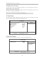
Standard CMOS Setup Page ....................................................................................... 2 3
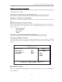
Advanced Setup ............................................................................................................ 2 5
Advanced Chipset Setup .............................................................................................. 2 6
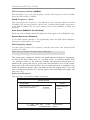
Integrated Peripherals ................................................................................................. 2 7
Power Management Setup .......................................................................................... 2 8
PCI/PnP Configuration ............................................................................................... 2 9
PC Health Status ..........................................................................................................3 0
Frequency/Voltage Control ...............................................................................31
Load Optimal Defaults ................................................................................................ 3 2
Supervisor Password .................................................................................................... 3 2
User Password ................................................................................................. 33
Save & Exit Setup ........................................................................................... 34
Exit Without Saving ......................................................................................... 34
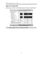
Chapter 4: Software & Applications .............................................................. 35
Introduction .................................................................................................................. 3 5
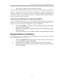
Installing Support Software ........................................................................................ 3 5
Bundled Software Installation .................................................................................... 3 7

iii
Motherboard User’s Guide
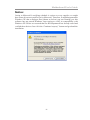
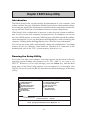
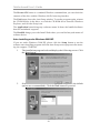
Notice:
Owing to Microsoft’s certifying schedule is various to every supplier, we might
have some drivers not certified yet by Microsoft. Therefore, it might happen under
Windows XP that a dialogue box (shown as below) pop out warning you this
software has not passed Windows Logo testing to verify its compatibility with
Windows XP. Please rest assured that our RD department has already tested and
verified these drivers. Just click the “Continue Anyway” button and go ahead the
installation.

1
Chapter 1: Introduction
Chapter 1 Introduction
This motherboard has a LGA 775 socket for latest Intel® Core
TM
2 Duo/Celeron
®
D processors with Hyper-Threading Technology and Front-Side Bus (FSB)
speeds up to 1333/1066/800/533 MHz. Hyper-Threading Technology, designed to
take advantage of the multitasking features gives you the power to do more things
at once.
This motherboard integrates the 945GC Northbridge along with Intel I/O Con-
troller Hub 7 (ICH7) that supports the Serial ATA interface for high-perfor-
mance and mainstream desktop PCs; the built-in USB 2.0 providing higher band-
width and implementing Universal Serial Bus Specification Revision 2.0.
It supports 6-channel High Definition Audio Codec and provides one IDE Ultra
ATA 100/66/33 channel. It has one PCIEX16 slot and two 32-bit PCI slots. There
is a full set of I/O ports including two PS/2 ports for mouse and keyboard, one serial
port, one optional LAN port, one VGA port, audio jacks for microphone, line-in
and line-out, and four back-panel USB 2.0 ports. In addition, onboard USB headers
provide extra ports by connecting the extended USB module to the motherboard.
It is an Micro ATX motherboard and has power connectors for a ATX power
supply.
Key Features
The key features of this motherboard include:
LGA775 Socket Processor Support
• Supports the latest Intel® Core
TM
2 Duo/ Celeron
®
D processors with
Hyper-Threading Technology
• Supports up to 1333/1066/800/533 MHz Front-Side Bus
Chipset
There are 945GC Northbridge and Intel I/O Controller Hub 7 (ICH7) in the
chipsets in accordance with an innovative and scalable architecture with proven
reliability and performance.
Note: 1. Hyper-Threading technology enables the operating system into thinking
it’s hooked up to two processors, allowing two threads to be run in parallel,
both on separate ‘logical’ processors within the same physical processor.
• Hyper-Threading Technology
2. Under ECS validation, this motherboard is able to support FSB 1333
MHz.

2
Motherboard User’s Guide
Onboard IDE connector
• One IDE connector that supports PIO (Programmable Input/Output)
and DMA (Direct Memory Access) modes
• Supports IDE Ultra DMA bus mastering with transfer rates of 100/66/33
MB/sec
• System Memory Controller Support
-Supports DDR2 SDRAM with up to maximum memory of 2 GB
• PCI Express Graphics Interface Support
-One PCIEX16 slot for Graphic Interface
• PCI Bus Interface
-Supports PCI Revision 2.3 Specification at 33 MHz
• Integrated Serial ATA Host Controller
-Supports four ports with data transfer rate up to 3.0 Gb/s
• Integrated IDE Controller
-Ultra ATA 100/66/33 Support
• USB 2.0
-Integrated USB 2.0 Host Controller supporting up to eight USB 2.0
ports
rates
• Low pin count for both host and devices
Serial ATA
• Four Serial ATA Connectors
• Transfer rate exceeding best ATA (~3.0 Gb/s) with scalability to higher
• 5.1 Channel High Definition Audio Codec
• All DACs support 192K/96K/48K/44.1KHz sample rate
• Software selectable 2.5V/3.75V VREFOUT
• Meets Microsoft WHQL/WLP 2.x audio requirements
• Direct Sound 3D
TM
compatible
Audio
Memory Support
• Two DIMM sockets for DDR2 667/533/400 DDR SDRAM with Dual-
channel architecture
• Maximum installed memory is 2 GB
Expansion Slots
• One PCIEX16 slot for Graphic Interface
• Two 32-bit PCI v2.3 compliant slots
• One 40-pin IDE connector that supports two IDE devices
• One floppy disk drive interface
• Four 7-pin SATA connectors

3
Chapter 1: Introduction
• Two PS/2 ports for mouse and keyboard
• One serial port
• One VGA port
• Four USB ports
• One LAN port (optional)
• Audio jacks for microphone, line-in and line-out
Onboard I/O Ports
• Integrated 10/100/1000 transceiver
• Supports PCI v2.3, 32-bit, 33/66 MHz
• Supports Wake-On-LAN (WOL) function and remote wake-up
• Supports 10/100 Mb/s N-Way Auto negotiation operation
• Half/Full duplex capacity
• Supports Wake-On-LAN (WOL) function and remote wake-up
The onboard LAN controller provides the following features:
Onboard LAN (optional)
• Power management
• Wake-up alarms
• CPU parameters and memory timing
• CPU and memory timing
The firmware can also be used to set parameters for different processor clock
speeds.
BIOS Firmware
This motherboard uses AMI BIOS that enables users to configure many system
features including the following:

4
Motherboard User’s Guide
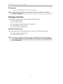
Optional Accessories
You can purchase the following optional accessories for this motherboard.
The Extended USB module
The Serial ATA cable
Note: You can purchase your own optional accessories from the third party,
but please contact your local vendor on any issues of the specification
and compatibility.
Package Contents
Your motherboard package ships with the following items:
The motherboard
The User’s Guide
One diskette drive ribbon cable (optional)
One IDE drive ribbon cable
The Software support CD
Dimensions
• Micro ATX form factor of 244 x 210 mm
Note: Hardware specifications and software items are subject to change
without notification.

5
Chapter 2: Motherboard Installation
Chapter 2 Motherboard Installation
To install this motherboard in a system, please follow these instructions in this
chapter:
Identify the motherboard components
Install a CPU
Install one or more system memory modules
Make sure all jumpers and switches are set correctly
Install this motherboard in a system chassis (case)
Connect any extension brackets or cables to headers/connectors on the
motherboard
Install peripheral devices and make the appropriate connections to head-
ers/connectors on the motherboard
Note: 1
2 Never connect power to the system during installation; otherwise, it
may damage the motherboard.
Before installing this motherboard, make sure jumper CLR_CMOS is
under Normal setting. See this chapter for information about locating
CLR_CMOS and the setting options.

6
Motherboard User’s Guide
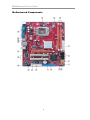
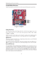
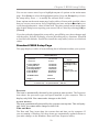
Motherboard Components

7
Chapter 2: Motherboard Installation
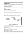
ITEM LABEL COMPONENTS
1CPU Socket
LGA775 Socket for Intel
®
Core™2 Duo/
Celer on
®
D CPUs
2 CPU_FAN CPU cooling fan connector
3 DIMM1/2 240-pin DDR2 SDRAM slots
4 ATX1 Standard 24-Pin ATX Pow er connector
5 SATA1~4 Serial ATA connectors
6 F_USB1~2 Front Panel USB headers
7 SPK1 Speaker header
8 USBPWR_F Front Panel USB Pow er Select Jumper
9 F_PANEL1 Front panel sw itch/LED header
10 IDE1 Primary IDE connector
11 CLR_CMOS Clear CMOS jumper
12 FDD Floppy Disk Drive connector
13 SPDIFO1 SPDIF out header
14 CD_IN1 Analog audio input connecor
15 F_AUDIO1 Front Panel Audio header
16 PCI1~2 32-bit add-on card slots
17 PCIEX16 PCI Express slot for graphics interface
18 USBPWR_R Rear Panel USB PS/2 Pow er Select Jumper
19 SY S_FA N Sys tem Fan c onnector
20 ATX12V1 4-pin +12V pow er connector
21 LPT1 Parallel port header

8
Motherboard User’s Guide
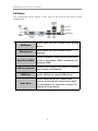
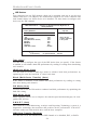
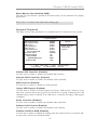
I/O Ports
The illustration below shows a side view of the built-in I/O ports on the
motherboard.
PS2 Mouse
Use the upper PS/2 port to connect a PS/2 pointing
device.
PS2 Keyboard
Use the low er PS/2 port to connect a PS/2
keyboard.
Serial Por t (COM1)
Use the COM port to connect serial devices such
as mice or fax/modems. COM1 is identif ied by the
system as COM1.
LAN Port (optional)
Connect an RJ-45 jack to the LAN port to connect
your computer to the Network.
USB Po r t s
Use the USB ports to connect USB devices.
Audio Ports
Use the three audio ports to connect audio
devices. The f irst jack is for stereo line-in signal.
The second jack is for stereo line-out signal. The
third jack is f or microphone.

9
Chapter 2: Motherboard Installation
This motherboard has a LGA775 socket for the latest Intel® Core
TM
2 Duo/
Celeron
®
D processors. When choosing a processor, consider the performance
requirements of the system. Performance is based on the processor design, the
clock speed and system bus frequency of the processor, and the quantity of inter-
nal cache memory and external cache memory.
This motherboard automatically determines the CPU clock frequency and system bus
frequency for the processor. You may be able to change these settings by making
changes to jumpers on the motherboard, or changing the settings in the system Setup
Utility. We strongly recommend that you do not over-clock processors or other
components to run faster than their rated speed.
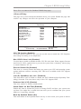
Installing the Processor
CPU Installation Procedure
Follow these instructions to install the CPU:
Warning: Over-clocking components can adversely affect the reliability
of the system and introduce errors into your system. Over-clocking can
permanently damage the motherboard by generating excess heat in
components that are run beyond the rated limits.
Fail-Safe Procedures for Over-clocking
When end-users encounter failure after attempting over-clocking, please take the
following steps to recover from it.
1. Shut down the computer.
2. Press and hold the “Page Up Key (PgUp)” of the keyboard, and then boot the PC
up.
3. Two seconds after the PC boots up, release the “Page Up Key (PgUp)”.
4. The BIOS returns to the default setting by itself.

10
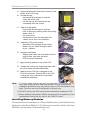
Motherboard User’s Guide
A. Read and follow the instructions shown on the
sticker on the CPU cap.
B. Unload the cap
· Use thumb & forefinger to hold the
lifting tab of the cap.
· Lift the cap up and remove the cap
completely from the socket.
C. Open the load plate
· Use thumb & forefinger to hold the
hook of the lever, pushing down and pulling
aside unlock it.
· Lift up the lever.
· Use thumb to open the load plate. Be
careful not to touch the contacts.
D. Install the CPU on the socket
· Orientate CPU package to the socket.
Make sure you match triangle marker
to pin 1 location.
E. Close the load plate
· Slightly push down the load plate onto the
tongue side, and hook the lever.
· CPU is locked completely.
F. Apply thermal grease on top of the CPU.
G. Fasten the cooling fan supporting base onto
the CPU socket on the motherboard.
H. Make sure the CPU fan is plugged to the
CPU fan connector. Please refer to the CPU
cooling fan user’s manual for more detail
installation procedure.
Note:
1. To achieve better airflow rates and heat dissipation, we suggest that you
use a high quality fan with 3800 rpm at least. CPU fan and heatsink
installation procedures may vary with the type of CPU fan/heatsink sup-
plied. The form and size of fan/heatsink may also vary.
2. DO NOT remove the CPU cap from the socket before installing a CPU.
3. Return Material Authorization (RMA) requests will be accepted only if the
motherboard comes with the cap on the LGA775 socket.
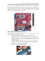
Installing Memory Modules
This motherboard accommodates two 240-pin DIMM sockets (Dual Inline Memory
Module) for unbuffered DDR2 667/533/400 memory modules (Double Data Rate
SDRAM), and maximum 2 GB installed memory.

11
Chapter 2: Motherboard Installation
Memory Module Installation Procedure
These modules can be installed with up to 2 GB system memory. Refer to the
following to install the memory module.
1. Push down the latches on both sides of the DIMM socket.
2. Align the memory module with the socket. There is a notch on the
DIMM socket that you can install the DIMM module in the correct
direction. Match the cutout on the DIMM module with the notch on
the DIMM socket.
3. Install the DIMM module into the socket and press it firmly down
until it is seated correctly. The socket latches are levered upwards
and latch on to the edges of the DIMM.
4. Install any remaining DIMM modules.
Over its predecessor DDR SDRAM, DDR2 SDRAM offers greater bandwidth and
density in a smaller package along with a reduction in power consumption. In
addition, DDR2 SDRAM offers new features and functions that enable a higher
clock rate and data rate operations of 400 MHz, 533 MHz and 667 MHz. DDR2
transfers 64 bits of data twice every clock cycle.

12
Motherboard User’s Guide
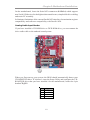
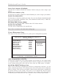
Please check the table below for the CPU FSB frequency and its corresponding memory
support frequency.
CPU FSB Frequency Memory Support Frequency
1333
DDRII533, DDRII667*
1066
DDRII533, DDRII667
800
DDRII400, DDRII533, DDRII667
533
DDRII400, DDRII533
*When you use a FSB1333-CPU on this motherboard, it will run at DDRII500 if you
adopt a DDRII533 memory module; and it will run at DDRII500 if “DRAM Frequency”
in “Frequency/Voltage Control” of BIOS is selected to “Auto”, while it will run at
DDRII667 when selected to “667MHZ”.

13
Chapter 2: Motherboard Installation
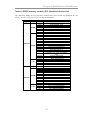
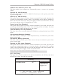
Table A: DDR2 (memory module) QVL (Qualified Vendor List)
The following DDR2 667/533 memory modules have been tested and qualified for use
when you use a FSB 1333-CPU on this motherboard.
Type Size Vendor Module Name
Corsair VC256MB533D2 4PB11D9CHM
Elpida Japan E2508AA-T7F-E
Kingmax Hynix HY5PS121621
Nanya NT5TU32M16AG-37B
Ramaxel 5PB42 D9DCD
Ramaxel Elpida D5116AF-5C-E
256 MB
Twinmos Elpida 8D22IB-ED
Aeneon Aeneon AET94F370
Aeneon Aeneon AET93F370
Corsair Samsung K4T51083QB-ZCD5
Corsair VS512MB533D2 64M8CEC
Elpida 04180WB01
Hynix HY5PS12821
Infineon HY818T512800AF37 33346778
Kingston Hynix HYB18T512800AF37
Kingston Hynix HY5PS12821
Kingston Nanya NT5TU64M8AE-37B
Ramaxel 5PB32 D9DCN
Ramaxel Elpida E5108AG-5C-E
Ramaxel 6AD11 D9GCT
Samsung
PC2-4200U-4444-10-B1 K4T51083QF-
ZCD5
Twinmos Samsung 8D22JB-KM
512 MB
Twinmos Elpida E5108AB-5C-E
Apacer Eipida E5108AB-5C-E
Geil A016E2864T2AG8AKT5H120001
Infineon HY818T512800AF37 33344539
Kingmax KKEA88E4AAKG-37
DDR2 533
1 GB
PQI PQI PQB2648D38R0651
256 MB
Infineon HYS64T325001HU-3-A HYB18T256
APOGEE AU51082-667P005
Corsair 64M8CFE PS1000545
Corsair VALUESELECT 32M8CEC
GEIL GL2L64M088BA18W
Infinity 0547W64M8 PC5300
PSC AL6E8E63B-6E1T
Ramxel 5LB31 D9DCL
Samsung K4T51083QC
Sync MAX 04400WB01 R050008A
Twinmos TMM6208G8M30B
512 MB
Transcend JetRam J12Q3AB-6
APOGEE AU51082-667P005
Infineon Aeneon AET93E30RB-0650
PSC AL6E8E63B-6E1T
DDR2 667
1 GB
PQI PQI PQB2648D38R0648

14
Motherboard User’s Guide
Jumper Settings
Connecting two pins with a jumper cap is SHORT; removing a jumper cap from
these pins, OPEN.
CLR_CMOS: Clear CMOS Jumper
Use this jumper to clear the contents of the CMOS memory. You may need to clear
the CMOS memory if the settings in the Setup Utility are incorrect and prevent
your motherboard from operating. To clear the CMOS memory, disconnect all the
power cables from the motherboard and then move the jumper cap into the CLEAR
setting for a few seconds.
Note: To avoid the system unstability after clearing CMOS, we recommend
users to enter the main BIOS setting page to “Load Optimal De-faults”
and then “Save Changes and Exit”.
Function Jumper Setting
VCC Short Pins 1-2
5VSB Short Pins 2-3
USBPWR_F/USBPWR_R: USB Power Select Jumper
Use these jumpers to select the voltage for USB port.
Note:1. Make sure the power supply provides enough SB5V voltage before
selecting the SB5V function.
2. It is required that users place the USBPWR_F & USBPWR_R cap onto 2-
3 pin rather than 1-2 pin as default if you want to wake up the computer
by USB/PS2 KB/Mouse.
Fun ct i o n
Jumper Setting
Nor mal
Short Pins 1-2
Clear CMOS Short Pins 2-3

15
Chapter 2: Motherboard Installation
Connect the power connector from the power supply to the ATX1 connector on
the motherboard. The ATX12V1 is a +12V connector for CPU Vcore power.
Connect the auxiliary case power connector to the ATX12V1 connector.
Connect the system cooling fan connector to SYS_FAN.
Connect the case speaker cable to SPK1.
Connect the case switches and indicator LEDs to the F_PANEL1 header. Please
refer to the following list of the F_PANEL1 pin assignments.
Install the Motherboard
Install the motherboard in a system chassis (case). The board is a Micro ATX size
motherboard. You can install this motherboard in a Micro ATX case. Make sure
your case has an I/O cover plate matching the ports on this motherboard.
Install the motherboard in a case. Follow the case manufacturer’s instructions to
use the hardware and internal mounting points on the chassis.
Pin Signal Pin Signal
1 HD_LED_P(+) 2 FP PWR/SLP(+)
3 HD_LED_N( - ) 4 FP PWR/ SLP( - )
5 RESET_ SW_ N( - ) 6 POWER_ SW_P( +)
7 RESET_ SW_ P( +) 8 POWER_ SW_N( - )
9RSVD 10KEY

16
Motherboard User’s Guide
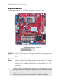
Connecting Optional Devices
Refer to the following for information on connecting the motherboard’s optional
devices:
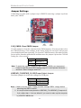
F_AUDIO1: Front Panel Audio Header
This header allows the user to install auxiliary front-oriented microphone and line-
out ports for easier access.
F_USB1/F_USB2: Front Panel USB Headers
The motherboard has USB ports installed on the rear edge I/O port array. Addition-
ally, some computer cases have USB ports at the front of the case. If you have this
kind of case, use auxiliary USB headers F_USB1/F_USB2 to connect the front-
mounted ports to the motherboard.
Pin Signal Pin Signal
1PORT1L 2GND
3 PORT1 R 4 PRESENCE#
5 PORT2R 6 Sense1_return
7 SENS E_ SEND 8 KEY
9 PORT2L 10 Sense2_return

17
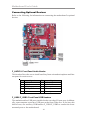
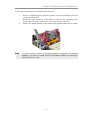
Chapter 2: Motherboard Installation
1 Locate the F_USB1/F_USB2 headers on the motherboard.
2 Plug the bracket cable onto the F_USB1/F_USB2 headers.
3 Remove a slot cover from one of the expansion slots on the system
chassis. Install an extension bracket in the opening. Secure the
extension bracket to the chassis with a screw.
Pin Signal Pin Signal
1 USBPWR 2 USBPWR
3 USB_FP_P0(-) 4 USB_FP_P1(-)
5 USB_FP_P0(+) 6 USB_FP_P1(+)
7GND 8GND
9 KEY 10 USB_FP_OC0
Here is a list of headers F_USB1/F_USB2 pin assignments.
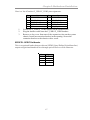
SPDIFO1: SPDIF Out Header
This is an optional header that provides an S/PDIF (Sony/Philips Digital Interface)
output to digital multimedia device through optical fiber or coxial connector.
Pin Signal
1SPDIFOUT
2+5V
3Key
4GND
Page is loading ...
Page is loading ...
Page is loading ...
Page is loading ...
Page is loading ...
Page is loading ...
Page is loading ...
Page is loading ...
Page is loading ...
Page is loading ...
Page is loading ...
Page is loading ...
Page is loading ...
Page is loading ...
Page is loading ...
Page is loading ...
Page is loading ...
Page is loading ...
Page is loading ...
Page is loading ...
Page is loading ...
-
 1
1
-
 2
2
-
 3
3
-
 4
4
-
 5
5
-
 6
6
-
 7
7
-
 8
8
-
 9
9
-
 10
10
-
 11
11
-
 12
12
-
 13
13
-
 14
14
-
 15
15
-
 16
16
-
 17
17
-
 18
18
-
 19
19
-
 20
20
-
 21
21
-
 22
22
-
 23
23
-
 24
24
-
 25
25
-
 26
26
-
 27
27
-
 28
28
-
 29
29
-
 30
30
-
 31
31
-
 32
32
-
 33
33
-
 34
34
-
 35
35
-
 36
36
-
 37
37
-
 38
38
-
 39
39
-
 40
40
-
 41
41


PC CHIPS P17G/1333 (V1.0A) User guide
- Category
- Motherboards
- Type
- User guide
Ask a question and I''ll find the answer in the document
Finding information in a document is now easier with AI
Related papers
-
ECS P49G (V1.0) User manual
-
PC CHIPS P29G (V1.0) User guide
-
-
-
-
PC CHIPS P53G (V1.0) User manual
-
-
-
-