Page is loading ...

INSTRUCTION MANUAL WARRANTY CERTIFICATE
CONTRACTOR
BY

Manual design and all elements of manual design are protected by U.S. Federal and/or State Law, including Patent, Trademark and/or Copyright laws.

The Minka-Aire® warranty is for one (1) year from the date of purchase from an authorized Minka-Aire® dealer.
This warranty is only valid to the original purchaser or user against all defects in material and workmanship (light bulbs
excluded) for one (1) full year. Additionally, Minka-Aire® warrants the motor only for the lifetime of the Minka Aire ceiling
fan (excluding wall controls and electrical components), to the original purchaser or user.
* The warranty is voided with the use of any non- Minka-Aire®electrical devices, E.g., wall controls or electrical dimmer switches, etc…
* The warranty is void once the original purchaser or user ceases to own the fan or the fan is moved from its original point of installation.
* The warranty is void with the use of any hanger bracket (non-Minka Aire or non-fan specific) other than the hanger bracket supplied & installed
with this specific fan.

Date Purchased Store Purchased Model Number Serial Number
F648
Warranty Service Information
To obtain warranty service during the warranty period, the purchaser should return the fan with the sales receipt to the original place of
purchase. The authorized Minka-Aire® dealer, at its sole discretion, will either repair or replace the fan after verifying the legitimacy of the warranty
claim. Replacement is subject to availability of the same model. If the model is unavailable it will be replaced by one of equal value. This is a
limited warranty; the original purchaser or user is responsible for the cost of removal and reinstallation of repaired or replacement product.
To obtain the name of the Minka-Aire® authorized dealer nearest you call the Minka-Aire® customer care department at 1-800-307-3267, or
contact Minka-Aire® through www.minkagroup.net and write to: “Ask Mr. Minka” to answer any questions or if you require assistance.

CONTENTS
SAFETY RULES.....................................................................................
PACKAGE CONTENTS.....................................................................
INSTALLING THE FAN.....................................................................
HANGING THE FAN.........................................................................
ELECTRICAL CONNECTIONS.......................................................
FINISHING THE INSTALLATION................................................
ATTACHING THE FAN BLADES..........................................................
LIGHT KIT INSTALLATION
.................................................................
OPERATING YOUR FAN.........................................................................
CARE OF YOUR FAN..............................................................................
TROUBLESHOOTING............................................................................
SPECIFICATIONS....................................................................................
1
2
3
4
5
6
7
8
9
10
11
12
1151 W. Bradford Court, Corona, CA 92882 For Customer Assistance Call: 1-800-307-3267

1
SAFETY RULES
1. Before you begin installing the fan, shut power off at the circuit breaker of the fuse box.
2. Be cautious!
Be cautious!
Read all instructions and safety information before installing your new fan. Review accompanying assembly diagrams.
3. Make sure that all electrical connections comply with local codes, ordinances, or National Electrical Codes. Hire a qualified electrician or consult a
do-it-yourself wiring handbook if you are unfamiliar with installing electrical wiring.
4. Make sure the installation site you choose allows the fan blades to rotate without any obstructions. Allow a minimum clearance of 7 feet from the
floor and 18 inches from the tip of the blades to the wall.
5. If you are mounting the fan to a ceiling fan outlet box, use a U.L. Listed metal octagonal outlet box marked "Acceptable for Fan Support". Secure
the box directly to the building structure. The outlet box and its support must be able to support the moving weight of the fan (at least 50
pounds) Do not use a plastic box.
6. Caution:
Caution:
To reduce the risk of injury use only the screws provided with the outlet box in conjunction with the lock washers provided with the fan.
7. If you are mounting the fan to a joist, make sure it is able to support the moving weight of the fan (at least 50 pounds).
8. After you install the fan, make sure that all mounting components are secured to prevent the fan from falling.
9. Do not insert anything into the fan blades while the fan is operating.
10. Turn the fan off and wait for the blades to stop completely before proceeding with maintenance or cleaning.

NOTE:
NOTE:
The important safeguards and instructions appearing in this manual are not meant to cover all possible conditions and situations that may
occur. It must be understood that common sense, caution and care are factors which can not be built into this product. These factors must be
supplied by the person(s) installing, caring for and operating the unit.
NOTE:
NOTE:
READ AND SAVE ALL INSTRUCTIONS!
WARNING
WARNING
TO REDUCE THE RISK OF FIRE, ELECTRIC SHOCK OR OTHER PERSONAL INJURY, MOUNT FAN ONLY TO A U.L. LISTED OUTLET BOX OR
SUPPORTING SYSTEM MARKED ACCEPTABLE FOR FAN SUPPORT AND USE MOUNTING SCREWS PROVIDED WITH THE OUTLET BOX IN
CONJUCTION WITH THE LOCK WASHERS PROVIDED WITH THE FAN. MOST OUTLET BOXES COMMONLY USED FOR FAN SUPPORT OF
LIGHTING FIXTURES ARE NOT ACCEPTABLE FOR FAN SUPPORT AND NEED TO BE REPLACED. CONSULT A QUALIFIED ELECTRICIAN IF IN DOUBT.
TO REDUCE THE RISK OF PERSONAL INJURY, DO NOT BEND THE BLADE HOLDERS WHILE INSTALLING, BALANCING THE BLADES OR CLEANING
THE FAN. DO NOT INSERT FOREIGN OBJECTS BETWEEN ROTATING FAN BLADES.
TO REDUCE THE RISK OF FIRE OR ELECTRONIC SHOCK, DO NOT USE THIS FAN WITH ANY SOLID-STATE SPEED CONTROL DEVICE.
ATTENTION:
ATTENTION:
The Energy Policy Act of 2005 requires this fan to be equipped with a 190 watt limiting device. If lamping exceeds 190 watts, the
ceiling fan's light kit will shut off automatically.

2
1. Fan blades (5)
2. Hanger bracket
3. Canopy
4. Standard downrod assembly
5. Fan motor/housing assembly
6. Blade holders (5)
7. Switch cup
8. Light kit
9. Glass shade
10. 13W GU24 CFL bulbs (2)
11. Balancing kit
A. Mounting hardware:
#10 x 1.5" Wood screws (2 PCs.)
#8 x 3/4" Machine screws (2 PCs.)
Lock washers (2 PCs.)
4mm star washers (2 PCs.)
Wire nuts (3 PCs. )
Washers (2 PCs.)
B. Blade attachment hardware:
3/16" x 7.5 mm screws (16 PCs.)
Fiber washers (16 PCs.)
C. Bracket holder hardware:
1/4" x 1/2" Screws with lock washers (11 PCs.)
D. Switch cup hardware:
Pull chain fobs (2 PCs.)
PACKAGE CONTENTS
Unpack your fan and check the contents. You should have the following items:
1
2
B
A
C
D
3
4
7
8
10
9
11
5
6

3
Tools Required: Phillips screw driver; slotted screw driver; step-ladder; wire cutters; electrical tape.
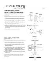
INSTALLING THE FAN
MOUNTING OPTIONS
If there isn't an existing mounting box, then read the following instructions. Disconnect the
power by removing fuses or turning off circuit breakers.
Secure the outlet box directly to the building structure. Use appropriate fasteners and building
materials. The outlet box and its support must be able to fully support the moving weight of
the fan (at least 50 lbs.). Use a UL Listed metal outlet box. Do not use a plastic outlet box.
Figure 1, 2 and 3 are examples of different ways to mount the outlet box.
Note:You may need a longer downrod to maintain proper blade clearance when installing on a
steep, sloped ceiling. Longer downrods are available from your Minka-Aire
®
dealer.
To hang your fan where there is an existing fixture but no ceiling joist, you may need to install
a hanger bar as shown in Fig. 4 (available at your Minka-Aire
®
dealer).
FIG. 1
FIG. 3
FIG. 2
FIG. 4
CROSS
BRACE
CEILING
JOIST
CEILING
jOIST
CEILING
JOIST
OUTLET BOX
PARALLEL WOOD BRACE
(MIN. 2" THICK)
OUTLET
BOX
OUTLET BOX
CEILING JOIST
OR CROSS BRACE
ANGLED CEILING
MAXIMUM 29°
ANGLE
PROVIDE
STRONG
SUPPORT
RECESSED
OUTLET BOX
HANGER
OPENING
MUST BE
FACING
UPSIDE
HANGER BAR
(OPTIONAL)
HANGER
BRACKET

4
WARNING:
WARNING:
All of the parts, hardware and components such as the
hanger bracket and hanger ball have been provided for your safety and
the proper installation of your new ceiling fan. The use of other parts,
hardware or components not supplied by Minka Aire
®
with the fan will
void the Minka Aire
®
Warranty.
REMEMBER
REMEMBER
to turn off the power. Follow the steps below to hang your
fan properly:
Step 1. Secure the Hanger Bracket to the ceiling outlet box using the screws
provided with your outlet box in conjunction with the lock washers
provided with the fan. (Fig. 5)
Step 2. Loosen the two Set Screws and remove the Hitch Pin and Lock Pin
from the coupling located on the top of the Motor Assembly. (Fig. 6)
Step 3. Remove the Hanger Ball from the Downrod Assembly by loosening
the Set Screw and removing the Cross Pin. (Fig. 7)
Step 4. Carefully feed fan wires up through the downrod. (Fig. 8) Thread
Downrod into the Coupling until the holes are lined up and secure with the
Lock Pin and Hitch Pin previously removed, tighten Set Screws. (Fig. 9)
Step 5. Slip Canopy onto Downrod. Carefully re-install the Hanger Ball onto
the Downrod being sure that it's properly positioned over the Cross Pin and
the wires are not twisted, tighten the Set Screws. (Fig. 9)
Step 6. Lift the Motor Assembly and place the Hanger Ball into the Hanger
Bracket. Rotate the Motor Assembly as needed until the check groove from
the Hanger Ball rests firmly over the registration tab from the Hanger
Bracket. Motor Assembly should not rotate if this is done correctly. (Fig. 10)
HANGING THE FAN

Fig. 9
DOWNROD
CANOPY
SET SCREWS
HITCH PIN
LOCK PIN
OUTLET BOX
HANGER BRACKET
DOWNROD
SUPPLY
WIRES
Fig. 5 Fig. 7 Fig. 8
Fig. 10
REGISTRATION
SLOT
CROSS PIN
HANGER
BALL
DOWNROD
SET SCREW
Fig. 6
HITCH
PIN
LOCK PIN
SET SCREWS

5
ELECTRICAL CONNECTIONS
REMEMBER
REMEMBER
to shut the power off at the circuit breaker or fuse box.
Follow the steps below to connect the fan to your house supply wires. Use the
wire nuts supplied with your fan. Secure the wire nuts by wrapping the
connection with electrical tape.
Step 1. Connect the black (hot) wire from the ceiling to the black and the blue
wires from the fan. Connect the white (Neutral) wire from the ceiling to the
white wire from the fan. (Fig 11)
Step 2. If your outlet has a ground wire (Green or Bare Copper) connect the fan
ground wires (on hanger ball and hanger bracket) to it; otherwise connect the
fan ground wire on hanger ball directly to the hanger bracket (Fig. 11)
Step 3. Figure 12 & 13 Illustrate the wiring connections using optional wall
unit. (Available at your Minka-Aire
®
Retailer.)
NOTE:
NOTE:
If a light kit is not included with your fan, one can be purchased at your
Minka-Aire
®
Retailer.
Fig. 11
BLACK (HOT)
WALL
WHITE (NEUTRAL)
GREEN (GROUND)
CEILING
HOUSE WIRE SUPPLY
BLUE (OPTIONAL LIGHT)
BLACK (MOTOR)
WHITE (NEUTRAL)
FAN CONTROLLED BY PULL CHAIN, LIGHT KIT CONTROLLED BY PULL CHAIN.
GROUND
(CONNECT TO GROUND
WIRE ON HANGER
BRACKET IF NO HOUSE
GROUND WIRE EXISTS.)

Fig. 12 Fig. 13
FAN CONTROLLED BY PULL CHAIN, LIGHT KIT CONTROLLED BY WALL SWITCH.
WIRING
OPTION 1
BLACK (HOT)
WALL
WHITE (NEUTRAL)
GREEN (GROUND)
CEILING
HOUSE WIRE SUPPLY
BLUE (OPTIONAL LIGHT)
WHITE (NEUTRAL)
LIGHT SWITCH
BLACK (MOTOR)
FAN CONTROLLED BY WALL CONTROL, LIGHT KIT CONTROLLED BY LIGHT SWITCH.
WIRING
OPTION 2
BLACK (HOT)
WALL
WHITE (NEUTRAL)
GREEN (GROUND)
CEILING
HOUSE WIRE SUPPLY
BLUE (OPTIONAL LIGHT)
BLACK (MOTOR)
WHITE (NEUTRAL)
LIGHT SWITCH
FAN WALL CONTROL
GROUND
(CONNECT TO GROUND
WIRE ON HANGER
BRACKET IF NO HOUSE
GROUND WIRE EXISTS.)
GROUND
(CONNECT TO GROUND
WIRE ON HANGER
BRACKET IF NO HOUSE
GROUND WIRE EXISTS.)
NOTE: SOME WALL UNITS
INCORPORATE BOTH LIGHT
SWITCH AND FAN WALL
CONTROL IN ONE HOUSING.

6
Step 1. Remove 1 of the 2 screws from the bottom of the hanger bracket and loosen the other one
half a turn from the screw head.
Step 2. Slide the canopy up towards the hanger bracket and place the key hole on the canopy
over the screw on the hanger bracket, turn canopy until it locks in place at the narrow section of
the key holes. (Fig. 14)
Step 3. Align the circular hole on canopy with the remaining hole on the hanger bracket, secure by
tightening the two set screws.
Note:
Note:
Adjust the canopy screws as necessary until the canopy are snug.
FINISHING THE INSTALLATION
Fig. 14
Outlet Box
Hanger
Bracket
Screw
Screw
Canopy

7
ATTACHING THE FAN BLADES
Step 1. Attach the fan blades to the blade holders
using the screws and fiber washers provided,
tighten screws securely. (Fig. 15)
Step 2. Remove rubber stops from motor. Align
motor holes to blade holders and secure with
screws provided, tighten screws securely. (Fig. 16)
NOTE:
NOTE:
You have the option of installing either five
or four blades. If you are using four blades, mount
blade holder to the inner screw holes of motor. If
you are using five blades, mount blade holder to
the outer screw holes of motor. (Fig. 16)
Fig. 15
Fig. 16
INNER
SCREW
HOLES
OUTER
SCREW
HOLES
FAN BLADE
BLADES HOLDER
SCREWS
FIBER
WASHERS

8
Fig. 17
REMEMBER:
REMEMBER:
To disconnect the power. The fan blades must be already attached to the fan.
ATTENTION:
ATTENTION:
The Energy Policy Act of 2005 requires this fan to be equipped with a 190 watt
limiting device. If lamping exceeds 190 watts, the ceiling fan's light kit will shut off automatically.
Step 1. Remove and discard the center plug from the switch cup. (Fig. 17)
Step 2. Feed the BLACK and WHITE wires from the light kit through the center hole of the switch
cup. Thread the switch cup to the nipple on the light kit. (Fig. 17) Make sure the light kit is
securely attached to the switch cup to prevent it from vibrating loose during fan operation.
LIGHT KIT INSTALLATION
SWITCH CUP
PLUG
LIGHT KIT
NUT
LOCK WASHER
WIRE NUT

Fig. 18
Step 3. Remove the screws from the switch cup plate. While holding the switch cup, firmly snap the
wire molexes together.
Step 4. Slide the switch cup up over the switch cup plate and rotate until the screw holes are
aligned. Secure the switch cup with three screws previously removed. (Fig. 18) CAUTION:
CAUTION:
Make sure that the wires are not pinched between the switch cup and the switch cup plate.
SWITCH
CUP
LIGHT KIT
SWITCH CUP
PLATE
CONECTOR
SCREWS

Fig. 19
Step 5. Install 2 x 13W GU24 compact fluorescent bulbs (included).
Step 6. Remove the finial, glass cap, nut, metal washer and rubber washer from the light kit. Raise
the glass shade up against the light kit stem, Place the rubber washer, metal washer and nut
over the stem and turn the nut clockwise until it locks up against the glass shade. Do not
Do not
overtighten.
overtighten.
(Fig. 19)
Step 7. Raise the glass cap and final against the glass shade and secure it to the stem by turning the
final clockwise until snug. Do not overtighten.
Do not overtighten.
(Fig. 19) Note:
Note:
Make sure to leave enough
space between the fan pull chain and the bulbs so the chain doesn't rub against any of the
bulbs.
BULBS
LIGHT KIT
GLASS
SHADE
RUBBER WASHER
METAL WASHER
NUT
FINIAL
GLASS CAP
PULL CHAIN

9
OPERATING YOUR FAN
Restore power to ceiling fan and test for proper operation.
Speed settings for warm or cool weather depend on factors such as the room size. Ceiling height, number of fans, etc.
The Reverse switch is located on the switch cup. Slide the switch to the Down for warm weather operation. Slide the switch to the Up for cool
weather operation.
NOTE:
NOTE:
Wait for fan to stop before changing the setting of the slide switch.
Warm weather - (Forward)
A downward airflow creates a cooling effect as shown in Fig. 20. This allows you to set your air conditioner on a warmer setting without affecting
your comfort.
Cool weather - (Reverse)
An upward airflow moves warm air off the ceiling area as shown in Fig. 21. This allows you to set your heating unit on a cooler setting without
affecting your comfort.
The pull chain controls the fan speed as follows: 1st pull - High , 2nd pul l - Med, 3rd pull - Low and 4th pul l - Off.

Fig 20
Fig 21
SUMMER OPERATION
WINTER OPERATION
/