Page is loading ...

MO-545 Made in USA
ECN 5539-MA 210122
OIL-FIRED CENTRAL FURNACE
Installation, Operation, and Service Manual
With Users Information Section
Models:
OD6FA072D48(B/R/C) OD6RA072D48(B/R/C)
OD6FA072DV5(B/R/C) OD6RA072DV5(B/R/C)
c
WARNING: IF THE INFORMATION IN THESE INSTRUCTIONS IS NOT FOLLOWED EXACTLY, A FIRE OR
EXPLOSION MAY RESULT CAUSING PROPERTY DAMAGE, PERSONAL INJURY, OR LOSS OF LIFE.
DO NOT STORE OR USE GASOLINE OR OTHER FLAMMABLE VAPORS AND LIQUIDS IN THE VICINITY OF
THIS OR ANY OTHER APPLIANCE.
c
WARNING: IMPROPER INSTALLATION, ADJUSTMENT, ALTERATION, SERVICE, OR MAINTENANCE CAN
CAUSE INJURY OR PROPERTY DAMAGE. REFER TO THIS MANUAL. FOR ASSISTANCE OR ADDITIONAL
INFORMATION CONSULT A QUALIFIED INSTALLER, OR SERVICE AGENCY.
c
AVERTISSEMENT: SI L'INFORMATION DANS CES INSTRUCTIONS N'EST PAS SUIVI À LA LETTRE, UN
INCENDIE OU UNE EXPLOSION ENTRAÎNANT DES DOMMAGES MATÉRIELS, DES BLESSURES
CORPORELLES OU DES PERTES DE VIE.
NE PAS ENTREPOSER NI UTILISER D'ESSENCE OU AUTRES VAPEURS ET LIQUIDES INFLAMMABLES À
PROXIMITÉ DE CET APPAREIL OU DE TOUT AUTRE APPAREIL.
c
AVERTISSEMENT: UNE MAUVAISE INSTALLATION, D'AJUSTEMENT, DE LA MODIFICATION,
D'ENTRETIEN OU DE MAINTENANCE PEUVENT CAUSER DES BLESSURES OU DOMMAGES MATÉRIELS,
REPORTEZ-VOUS À CE MANUEL POUR OBTENIR DE L'AIDE OU DES RENSEIGNEMENTS
SUPPLÉMENTAIRES, CONSULTER UN INSTALLATEUR QUALIFIÉ, OU ORGANISME DE SERVICE.
PLEASE READ THESE INSTRUCTIONS PRIOR TO INSTALLATION, INITIAL FIRING, AND BEFORE
PERFORMING ANY SERVICE OR MAINTENANCE. THESE INSTRUCTIONS MUST BE LEFT WITH THE USER
AND SHOULD BE RETAINED FOR FUTURE REFERENCE BY QUALIFIED SERVICE PERSONNEL.
VEUILLEZ LIRE CES INSTRUCTIONS AVANT L'INSTALLATION, LES PREMIERS TIRS, ET AVANT
D'EFFECTUER TOUT ENTRETIEN OU MAINTENANCE. CES INSTRUCTIONS DOIVENT ÊTRE LAISSÉS AVEC
L'UTILISATEUR ET DEVRAIT ÊTRE CONSERVÉ POUR RÉFÉRENCE FUTURE PAR UN TECHNICIEN
QUALIFIÉ.
Manufactured by:
THERMO PRODUCTS, LLC.
PO BOX 237
DENTON, NC 27239

1
Contents
SECTION PAGE
Notice to the Installer .................................................................................................. 3
INSTALLATION GUIDELINES ...................................................................................... 5
Codes ................................................................................................................. 5
Installation Location ............................................................................................ 5
Closet and Alcove Installation ............................................................................. 6
Standard Clearances .......................................................................................... 6
Air for Combustion and Ventilation ..................................................................... 7
Chimney Inspection ............................................................................................ 9
Flue / Chimney / Vent Connector ........................................................................ 10
Blocked Vent Switch ………………………………………...................................... 10
Draft Regulator ……………………………………………....................................... 10
Direct Venting ………………………………………………..................................... 11
Power (Side-Wall) Venting – Important Note Regarding ..................................... 11
Duct Work and Air Conditioning .......................................................................... 12
Air Filter Mounting ............................................................................................... 12
Electrical Connections ........................................................................................ 13
Room Thermostat ............................................................................................... 13
Combustion Chamber ......................................................................................... 14
Oil Burner and Oil Nozzle Installation .................................................................. 14
Fuel System Installation ....................................................................................... 16
INITIAL OPERATION OF THE FURNACE .................................................................... 16
Initial Burner Operation ....................................................................................... 16
Supply/Return Airflow and Air Temperature ........................................................ 17
Furnace Limit and Blower Controls ..................................................................... 18
Operational Modes ……………............................................................................ 19
Instructions to Our Customer / End User .............................................................. 21
SERVICE ....................................................................................................................... 21
Control Diagnostics ............................................................................................... 21
Troubleshooting .................................................................................................. 22
Flame Sensor (“Cad Cell”) Checkout Procedure ................................................ 24
Replacement Parts ............................................................................................. 24
MAINTENANCE ............................................................................................................. 24
Air Filter(s) ........................................................................................................... 24
Oil Burner ............................................................................................................ 24
Blower and Motor ................................................................................................ 25
Heat Exchanger .................................................................................................. 25
Flue and Chimney ............................................................................................... 26
USERS INFORMATION ................................................................................................. 27

2
Operating Instructions ........................................................................................ 27
Oil Supply ........................................................................................................... 28
Extended Shutdown ........................................................................................... 28
Combustion Air and Ventilation Supply ................................................................ 29
Inspection Areas ................................................................................................. 29
APPENDIX A: START-UP DATA SHEET ..................................................................... 30
APPENDIX B: ELECTRICAL DIAGRAMS ..................................................................... 31
APPENDIX C: SPECIFICATION SHEETS .................................................................... 35
APPENDIX D: REPLACEMENT PARTS ....................................................................... 36

3
Notice to the Installer
Installation of this oil-fired furnace must be performed by a qualified installer in
accordance with all local codes and authorities having jurisdiction. In the absence of
local governing codes, installation shall conform to these instructions and to the
regulations of the National Fire Protection Association’s Standard for the Installation of
Oil-Burning Equipment, NFPA 31-2020, and the National Electrical Code, ANSI/NFPA
70-2017, or the latest editions thereof.
A qualified installer, also referred to in this instruction manual as a “qualified heating
contractor”, is an individual, or agency, properly licensed and experienced to
install and service oil-burning equipment in accordance with all local codes and
ordinances.
Material and Workmanship
This furnace was built with the highest quality materials and attention to
workmanship. However, omissions and defects occasionally occur. Before
installing the furnace, inspect the furnace thoroughly. If missing parts, defective
material, or poor workmanship is evident, report the model and serial numbers
imprinted on the furnace rating label to the seller for adjustment.
Packaging
A complete furnace is contained within a single package. The factory completed
all feasible assembly. However certain components including draft regulator and,
if supplied, door handle, air filter(s), and air filter rack(s), must be assembled to
the furnace, or the venting system, in the field. Refer to the assembly
instructions.
Shipping Damage
If this furnace was damaged during transit, please immediately request the
transportation company inspect the furnace and issue a concealed damage
report. The party receiving the furnace should file the claim for shipping damage.
Report any shipping damage immediately.
It is absolutely essential that a damage report be obtained. If a concealed
damage report is not obtained, we cannot provide assistance in recovering your
claim against the transportation company.
Warranties
c
WARNING: The manufacturer of this equipment assumes no liability for
any damages resulting from unauthorized modifications made to the
furnace, or any components thereof, or improper installation of the furnace

4
in the field. Furthermore, any such field modifications VOID THE
WARRANTY and place responsibility for safe and reliable operation of the
furnace on those who performed the modification(s).
Complete and return any enclosed warranty cards. These must be on file to
verify installation dates for replacement of any warrantied part(s).

5
INSTALLATION GUIDELINES
Codes
All local codes and regulations take precedence over the instructions in this
manual and shall be followed accordingly. In the absence of local codes, this
installation must conform to these instructions and to the regulations of the
National Fire Protection Association (NFPA) publications, the Standard for the
Installation of Oil-Burning Equipment, NFPA 31-2020, and the National Electrical
Code, ANSI/NFPA 70-2017 or the latest editions thereof,
Installation Location
c
WARNING:
These furnaces are designed for indoor installation ONLY.
These furnaces are NOT to be used as construction heaters.
DO NOT hang the horizontal / counterflow furnace from a
structure, or surface, by any integral part or fastener of the
furnace. The furnace was not designed to support itself in this
manner.
In as much as practical, the furnace should be positioned near a chimney or vent
and should be centralized with respect to the air distribution system.
For a utility room installation, the entrance door must be wide enough to permit
the largest part of the furnace to pass through the doorway or allow sufficient
clearance to permit the replacement of another appliance, e.g. a water heater, in
the room.
If the furnace is installed in a residential garage, it must be installed so the burner
is located higher than 18 inches above the floor, unless the required combustion
air is taken from the exterior of the garage. Also, the furnace must be located or
protected to avoid physical damage from impacts by vehicles.
It is recommended that a commercially available CO alarm be installed in
conjunction with any fossil fuel burning appliance. The CO alarm shall be
installed according to the alarm manufacturer’s installation instructions and be
listed in accordance with the latest edition of the UL Standard for Single and
Multiple Station Carbon Monoxide Alarms, UL 2034, or the CSA International
Standard, Residential Carbon Monoxide Alarming Devises, CSA 6.19.
The furnace shall not be operated in a condition where the return air is
consistently below 55°F.

6
Closet and Alcove Installation
All furnace models covered in this manual may be installed in a closet or alcove
with specified (standard) clearances to combustible construction. When installed
in a counterflow configuration a combustible surface-mounting base (Model # D6-
BASE) must be used for when installing on combustible materials, refer to Figure
1.
Figure 1: Counterflow Furnace Combustible Surface-Mounting Base
Standard Clearances
Standard clearances are mandatory minimum clearances from heated surfaces
of the furnace to combustible materials to assure protection from fire hazard
during furnace operation. (Refer to the Standard for the Installation of Oil-Burning
Equipment, NFPA 31-2020, or latest edition, for definitions of combustible and
non-combustible materials.
Accessibility clearances, which are typically greater, may exceed fire protection
clearances. Therefore, consider providing at least 24 inches of clearance from
the front of the furnace to obstructions and surfaces for adequate service and
maintenance access.
The minimum clearances from furnace casing surfaces to combustible materials
are:
0 inches from casing sides and rear
6 inches from front casing of furnace
7 inches from flue pipe/vent connector
1 inches from casing top
1 inches from any side of supply air plenum
1 inches above supply air ducts, within 6 feet of furnace

7
Air for Combustion and Ventilation
c
CAUTION: Relief openings in the front or top of the furnace casing
should not be obstructed or blocked. These openings supply combustion
and ventilation air to the furnace.
Chloride, fluoride, iodide, and bromide bearing compounds when present, even
in low concentrations, are in air supplied for combustion to the furnace, can result
in accelerated and severe corrosion of the heat exchanger and/or the venting
system.
Often, household chemicals contain chloride-bearing compounds. There are
many compounds representative of this classification of chemicals. A few
common examples are listed below.
Cleaning solvents
Varnish and paint removers
Bleaches
Fabric softeners
Water softener salt
Tile adhesives
Avoid storing or using these chemicals within close proximity to the furnace. In
addition, avoid storing or using any chemicals, of an unknown and possibly
flammable nature, in close proximity to the furnace.
The furnace shall be installed in a location within the building that permits a
satisfactory supply of air for combustion, ventilation, and proper operation of the
venting system. While all forms of building construction cannot be covered in
detail in this manual, this requirement may usually be met by application of one
of the following methods in ordinary building construction. However, applicable
local installation codes always take precedence and shall be followed.
The content of certain pertinent passages of NFPA on methods to obtain and
ensure adequate airflow to the furnace has been excerpted and, in some cases,
paraphrased below for reference purposes. Consult the Standard for the
Installation of Oil-Burning Equipment, NFPA 31-2020, or latest addition for
special cases and further details.
1. Utility Room (example of a confined space)
a. In buildings of conventional construction with normal air infiltration, two
(2) permanent openings connecting to a well-ventilated crawl space,
attic, or another large, well-ventilated internal area shall be provided.
Each opening shall have a minimum free area of one (1) square inch
per 1000 BTUH of total input rate (sum of the individual appliance input
rates) of all appliances to be installed in the utility room. One opening

8
should be located near, or in, the ceiling of the room and the other
should be located near, or in, the floor.
b. In buildings of unusually tight construction (those having 0.35 air
changes per hour, or less); provision must be made to provide
sufficient air for combustion. The following method will usually be
adequate to ensure sufficient airflow into the space.
Provide two (2) permanent openings, one (1) located within 12 inches of the floor
and one (1) within 12 inches of the ceiling, or roof, of the room. These openings
shall allow for direct exchange of air between the room and outdoors. If required,
ducting between the room and the outdoors shall be provided.
For horizontally -oriented ducts, each opening shall have a
minimum free area of one (1) square inch per 2000 BTUH of the
total input rate (sum of the individual appliance input rates) of all
appliances to be installed in the room.
For vertically -oriented ducts, the minimum free area may be
reduced to one (1) square inch per 4000 BTUH of the total input
rate (sum of the individual appliance input rates) of all appliances to
be installed in the room.
The minimum dimension of any air opening shall not be less than 3-
inches.
When an opening in the outside wall must be provided, it should be
furnished with properly screened metal sleeves.
2. Full Basement (example of an unconfined space)
a. Where a furnace is installed in a full basement, in a building of
conventional construction with normal air infiltration, infiltration is
normally adequate to provide air for combustion and ventilation.
b. In buildings of unusually tight construction (such as those where
weather stripping and storm sash windows are used, and where
basement windows are also weather-stripped), one (1) permanent
opening connecting to a well-ventilated attic, or with the outdoors shall
be provided, using a duct, if necessary. This opening shall have a
minimum free area of one (1) square inch per 5000 BTUH of total input
rate (sum of the individual appliance input rates) of all appliances to be
installed in the basement.
When an opening in the outside wall must be provided, it should be furnished
with properly screened metal sleeves.
If an exhaust fan or additional air consuming machines (e.g. a cloth dryer), is
present in the furnace room, there should be increased concern about providing
adequate airflow to the furnace. Additional efforts may be required to assure an
adequate supply of combustion and ventilation air is available to the furnace
under all conditions.

9
When needed it is possible to have combustion air connected directly to the
burner of these furnaces to the outdoors by using appropriate Combustion Air Kit
listed below.
Table 1: Combustion air intake hood kits
Chimney Inspection
The chimney, vent, or any passageway for the stack gases to flow to the outdoor
atmosphere is a very important part of the heating system. No furnace,
regardless of the efficiency of the design, can perform satisfactorily when the
chimney to which it is connected is inadequate or in poor condition. Any of the
following symptoms may indicate a chimney has severe structural damage and is
unsuitable for use.
Chimney appears to be leaning to the side.
Chimney appears to have structural damage, i.e. loose or missing blocks
or bricks, or excessive deterioration at mortar joints.
Tile liner damaged or missing.
Flue gas leakage along the length of the chimney between the chimney
connector and discharge termination.
Excessive corrosion at the cleanout port or at the chimney connector
entrance into the chimney.
Structural debris, i.e. mortar or tile liner flakes, in base of the flue way.
A qualified person shall inspect the chimney to confirm it is correctly sized for the
application, properly constructed, and in sound condition. Refer to the Standard
for the Installation of Oil-Burning Equipment, NFPA 31-2001, for details on proper
chimney sizing and construction. If needed, the chimney should be cleaned
before installing the furnace. Any accumulation of dirt or debris at the bottom of
the flue should be removed.
COMBUSTION AIR INTAKE HOOD KIT ORDER INFORMATION
BURNER THERMO PRODUCTS PART NUMBER
Beckett AFG AOPS8397
Riello BF3 AOPS8416
Carlin EZ-1HP AOPS8433

10
Flue / Chimney / Vent Connector
c
CAUTION:
DO NOT install a manual damper in the chimney or vent connector.
Thermally- activated type vent dampers are NOT recommended for
use on these furnaces.
It is desirable to install the shortest vent connector (also referred to as a flue or
chimney connector) possible with the fewest number of fittings, i.e. transitions
and elbows. Generally, 6-inch diameter, 24 Ga. or heavier, single wall, lock
seam-type, galvanized steel vent pipe and fittings are satisfactory materials for
the fabrication of a vent connector. However, always consult local codes and
authorities for specific minimum requirements.
On a front flue unit the flue can exit through the top, left or right side casing, or
through the front door. Remove the appropriate knock-out in the casing panel for
the chosen venting location.
All horizontal sections of the vent connector must slope upward not less than ¼
inch per foot from the furnace to the vent termination. Long horizontal sections of
the venting system must be supported at least every five (5) feet with metal
straps to prevent sagging of the vent piping. Secure all joints in the vent
connector with sheet metal screws or equivalent fasteners. Vent piping must not
be inserted beyond the inside wall of the chimney flue.
Blocked Vent Switch
The blocked vent switch kit must be installed to comply with CAN STD B140.4
where applicable. Installation instructions are provided with the Blocked Vent kit,
part no. AOPS2686
Draft Regulator
A barometric-type, draft regulator is supplied with the furnace. Installation or
operating conditions that produce excess amounts of draft can reduce the
heating efficiency of the furnace. The purpose of the regulator is to adjust and
control the flow of flue gases from the furnace by stabilizing the amount of
chimney draft to which the furnace is subjected.
Always refer to the draft regulator manufacturer’s installation instructions for
application specific recommendations.

11
Direct Venting
The OD6 may also be horizontally vented through a side wall. Direct venting is
only allowed when using the approved Direct Vent Termination kit and Direct
Vent Accessory kit listed in the table below, and is limited to a maximum length
of 15’.
Table 2: Side wall vent kits
The Direct Vent Termination kit consists of a concentric through-the-wall vent
termination/inlet air vent hood and 15’ of Stainless Steel Insulated Flexible Pipe
that requires 2” clearance to combustibles.
A field supplied smooth wall 4” combustion air pipe will need to be provide to
connect the combustion air from the termination hood to the burner. The direct
vent accessory kit will provide the fittings needed to connect the 4” pipe to the
burner. The combustion air inlet can be installed through the either the lower left
or right side casing knock-out.
For proper installation follow the Instruction provide with the Direct Vent
Termination Kit.
Power (Side-Wall) Venting – Important Note Regarding
c
CAUTION: Thermo Products, LLC will NOT assume responsibility for
damage to, and deterioration of, exterior building materials, e.g. brick,
siding, clapboards, and etc., in close proximity to the vent terminal due to
operation of a power vented, oil furnace. This policy is applicable
regardless of the cause of sooting.
NOTICE: Thermo Products recommends the use of a chimney to vent
residential oil furnaces. If a power venter must be used, it is the
responsibility of the installer and power venter manufacturer to design,
assemble, and demonstrate proper operation of the power venting system
with the furnace.
SIDE WALL VENTING APPLICATION ORDER INFORMATION
BURNER
VENT TERMINATION KIT
(15’ application MAX)
PART NUMBER
SIDE WALL VENT
ACCESSORIES KIT
PART NUMBER
Beckett AFG AOPS8393 AOPS8394
Riello BF3 AOPS8393 AOPS8395
Carlin EZ-1HP AOPS8393 AOPS8432

12
Duct Work and Air Conditioning
Design and installation of the duct system should follow the current guidelines of
the Air Conditioning Contractors of America (ACCA) or the American Society of
Heating, Refrigeration and Air Conditioning Engineers, Inc. (ASHRAE). Refer to
the Residential Duct Systems, Manual D, from the ACCA, and the ASHRAE
Handbook Fundamentals volume, from ASHRAE, for recommended practices in
duct system design and installation.
All furnaces are tested over a range of external static pressure that simulates the
airflow resistance of the ductwork, fittings, and diffusers connected to the furnace
for a typical (average) duct system. The furnace blower and blower motor have
been selected to work successfully against the following range of duct system
resistance.
Recommended range of the duct system external static pressure for all
models: 0.2 to 0.5 in. W.G...
Due to the need to maintain an adequate supply of combustion and ventilation
air, the furnace shall not be installed in small room without return air duct system.
A return air duct shall be connected to the furnace return air opening and extend
to a location outside the furnace room.
If the furnace is used in connection with a cooling coil, the coil must be installed
in parallel with, or on the supply side of the furnace to avoid water vapor
condensation in the furnace heat exchanger. If the cooling unit is installed in a
parallel flow arrangement, dampers (or other means used to control airflow)
should be provided to prevent chilled air from entering the furnace. If such a
damper is manually operated, it must be equipped with a means to prevent
operation of either unit, unless the damper is placed in either the full heat or full
cool position.
NOTICE: Return air grilles and supply registers in the air distribution
system should never be obstructed.
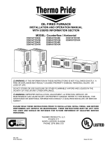
Air Filter Mounting
The OD6 comes with (2) two 19” x 13” reusable filters. A “W” style filter rack is
shipped with the furnace for placement of the filters inside the return air plenum
on counterflow installations. Access to the filters is through the removable blower
door. For horizontal installations, it is recommended that return air grill filters be
installed for homeowner access. See Fig. 2.

13
19.125"
3.000"
Fig. 2: Filter rack and dimensions for the OD6 furnace
Electrical Connections
NOTICE: All field wiring must conform to local, state, and national
installation codes.
A disconnecting switch equipped with overcurrent protection rated at 15 A. (e.g. a
time delay-type fuse or inverse time, circuit breaker) should be installed in the
service line.
Since the furnace is entirely pre-wired at the factory, it is only necessary to
connect the building electrical service lines to the two (2) pigtail wires extending
from the junction box. The junction box is mounted inside the furnace burner
compartment or mounted on the front exterior of the furnace, in the case of the
horizontal / counterflow model. A ground connection must also be made in the
junction box. The service lines to the furnace should be no smaller than 14 Ga.,
insulated copper wire with a temperature rating of 60ºC, or greater.
Refer to the electrical diagrams contained in Appendix B of this manual for an
electrical schematic, a connection diagram, and operating instructions.
Room Thermostat
A room thermostat must be connected to the Oil Furnace control. This is
typically a low voltage (24 VAC) circuit. Consult the National Electrical Code,
ANSI/NFPA 70-2017, or latest edition for guidelines for proper wiring methods
and materials for this circuit. The room thermostat should be located on an
interior wall in the natural circulating path of the room air.
The thermostat should not be installed in a location where it is directly exposed
to,
cold air infiltration, i.e. drafts from outside openings such as windows and
doors,
air currents produced by supply air registers, and
heat from a nearby source, such as a fireplace, electrical appliances,
lamps, solar radiation, a wall enclosing warm air ducts, a chimney, or a
flue gas vent.

14
Most room thermostats are equipped with an adjustable heat anticipator, set the
thermostat heat anticipator to match the control current of the furnace as indicted
on the furnace wiring diagram.
Combustion Chamber
The furnace combustion chamber is a hollow, circular cylinder sealed at the
bottom end and open at the top end. The chamber is made of a lightweight,
insulating, “soft”, refractory material. The refractory material is composed of
organically bound, alumina-silica fibers that protect the heat exchanger from the
intense heat of the oil burner.
Oil Burner and Oil Nozzle Installation
c
CAUTION: This oil furnace is designed to use No. 2 or lighter distillate
fuel (home heating) oil. A Bio-fuel mixture may be used but the mixture is
not to exceed a B5.
This furnace is designed to utilize the following specially modified, oil burner:
R.W. Beckett Corp. model AFG burner, specification # TP2501
Riello model BF3, specification # C8511325
Carlin model EZ-1HP, specification # 99032B
NOTICE: NO other burners may be used in this application.
The heat output from the furnace is fixed, based on the size of nozzle installed in
the oil burner. Three (3) heat input rates are permissible: 70,000, 85,000, and
106,250 BTUH.
Nozzle selection (i.e. heating capacity of the furnace) shall be based on a rate of
heat loss (heating load) calculation for the building. These calculations should be
made according to the manuals provided by the Air Conditioning Contractors of
America (ACCA) or the American Society of Heating, Refrigeration and Air
Conditioning Engineers, Inc. (ASHRAE).
Refer to the Residential Load Calculation, Manual J, from the ACCA, and the
ASHRAE Handbook Fundamentals volume, from ASHRAE, for the
recommended procedure to compute the design heating load of a residence.
NOTICE: Remove all cardboard packing from around chamber before installing
burner.
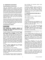
For horizontal installation rotate mounting plate and chamber retainer 90 degrees
left or right, depending on furnace position. DO NOT change the position of the
chamber. This unit is equipped with a chamber retainer. The retainer secures the

15
COUNTERFLOW
CHAMBER RETAINER
FR ONT FLU E MODELS S HOWN
SHOWN WI T H WARM AIR
OUT LET ON L EFT END
HORIZONTAL
OVERFIRE DRAFT
ACCESS COVER
OVERFIRE DRAFT
ACCESS PORT
NUT & WASHER
(4) PLACES
BURNER MOUNTING PLATE
BURNER MOUNTING
PLATE GASKET
COMBUSTION CHAMBER
CHAMBER RETAINER
OVERFIRE DRAFT
ACCESS COVER
OVERFIRE DRAFT
ACCESS PORT
NUT & WASHER
(4) PLACES
BURNER MOUNTING PLATE
BURNER MOUNTING
PLATE GASKET
CHAMBER RETAINER
COMBUSTION CHAMBER
chamber during shipping and helps to maintain insertion depth. DO NOT remove
this retainer when installing burner. (Refer to Fig.3).
Fig. 3: Burner Mounting Plate for Counterflow and Horizontal Installations
When mounting the burner, (Fig 4) do not allow the burner tube or end cone to
physically touch or protrude into the chamber, as excess heat transfer could
result in destruction of the tube, end cone or both. The burner tube/end cone is
properly positioned, when the end is ¼ inch back from the inside surface of the
combustion chamber wall. A fiber insulating sleeve is provided with the Riello
BF3 Burner.
Fig. 4: Burner Insertion Illustration (Top view)
The oil burner provided with this furnace requires initial inspection, set-up, and
proper adjustment. Refer to this manual and the oil burner manufacturer’s
operating instructions for detailed information on the following items.
Initial firing of burner
Adjusting the burner combustion air
Adjusting the fuel pump pressure
Setting the draft control

16
NOTICE: This oil furnace must be installed and adjusted by only qualified
oil heating contractor using calibrated combustion test instruments to
ensure safe and reliable operation of the furnace.
Fuel System Installation
In situations where the oil storage tank is installed at the same level with, or
above, the burner, a single oil supply line run from the oil tank to the burner will
be usually be adequate. No return line will be required. If the oil tank is installed
below the burner and the lift exceeds approximately 6-ft., an oil supply line and
an oil return line are recommended.
Refer to the Standard for the Installation of Oil-Burning Equipment, NFPA 31-
2020, or latest edition and the oil burner operating instructions for detailed
information on oil storage tank & oil supply/return line installation.
NOTICE: We recommend installing a high efficiency oil filter, in the oil
supply line, capable of filtering 10 to 20 micron diameter (or preferably
smaller) particles from the fuel.
Initial Operation of Furnace
Initial Burner Operation:
c
IMPORTANT: The start-up sheet found in Appendix A of this manual should be
completed.
1. Turn the electrical disconnecting switch to the “OFF” position.
2. Set the room thermostat above room temperature.
3. Be sure the oil tank is full of clean # 2 fuel oil.
4. Open all shutoff valves in the oil line.
5. Refer to the oil burner manufacturer’s operating instructions (included
with the furnace) for detailed startup instructions
6. Measure the oil pump pressure. If required, adjust it to deliver the
appropriate pressure for the burner. The oil pump should be set to
produce,
120 PSIG, for the R.W. Beckett model AFG burner
140 PSIG, for the Riello model BF3
120 PSIG, for the Carlin model EZ-1HP
7. Carbon Dioxide (CO2) and Carbon Monoxide (CO) – In order to assure
that proper and safe combustion are taking place, carbon dioxide and
carbon monoxide measurements must be taken. A CO2 reading within

17
the limits of appendix C with no measurable CO is desirable. The
maximum acceptable CO reading is about 50 PPM. If the CO reading
is too high, open the burner air shutter, or air band, slightly to permit
more combustion air to the flame. Recheck the CO level and adjust as
required.
8. Draft – Draft measurements should be taken through the overfire port
and in the vent connector, not more than 12 inches away from the
furnace outlet. A 5/16 in. hex washer head bolt plugs the overfire port
in the burner mounting plate. Remove the bolt and insert a suitable
draft measurement gage.
9. Flue Gas Temperature – The flue gas temperature will vary depending
on heat input rate, air temperature rise across the heat exchanger, and
air flowrate through the furnace. To prevent excessive water vapor
condensation from the flue gases, the gross flue gas temperature
should not fall below 330ºF. In addition, if the gross flue gas
temperature exceeds 650ºF, the heating efficiency of the furnace will
be reduced.
10. Cycle the furnace several times to verify the burner lights off and shuts
down smoothly without excessive noise or smoke production.
Supply/Return Airflow and Air Temperature (PSC)
The supply/return airflow shall be set to obtain an air temperature rise, across the
furnace, in the range of 51º to 81ºF. Since the flow resistance of each duct
system is slightly different, the airflow (fan speed) may have to be changed in the
field to achieve a satisfactory temperature rise.
The blower (fan) speed is adjusted by changing the fan motor winding energized
by the control system. The furnace is set on the med-low fan speed, “ML”, at the
factory; refer to furnace wiring diagram, Appendix B. To adjust the fan speed,
follow this procedure.
a. Turn off all electrical power to the furnace at the disconnecting switch.
b. Remove the blower compartment access door on the
counterflow/horizontal furnace.
c. The “Heat” tab is the connection for the heating speed activation thru the
fan board. If a change in heating speed is desired simply pull the wire
from the heat tab and replace it with the desired motor speed wire. The
Black (High) is connected to the “cool” tab for A/C speed operation. If a
lower speed is desired for A/C, the speed is changed the same way. A
tab marked “Low” is populated with a lower fan speed for continuous fan
operation thru the “G” circuit of your T-stat. Unused blower speeds are
connected to the “unused motor leads” tabs at bottom right of fan board.
d. Replace the blower compartment access door on the
counterflow/horizontal unit.
e. Restore electrical power to the furnace at the disconnecting switch.

18
f. Recheck Temperature rise and adjust if needed.
Note: For furnace models with an ECM Blower Motor Refer to ECM Operation
Manual provided with those furnaces for ECM blower speed adjustments.
Furnace Limit and Blower Controls
! WARNING: The predetermined fan and limit locations on all of the Thermo
Pride oil fired furnaces have been tested and approved by Thermo
Products, LLC. Any attempt to relocate these safety controls or replace
these safety controls with a control that is not approved, or is
incompatible, may result in personal injury, substantial property damage or
death.
Thermo Pride oil furnaces can be equipped with one of the following two boards.
Please refer to Fig. 5 to see which board you have.
Wiring Diagrams and Fan Speed Selection Charts can be found in this manual
under Appendix B .
Refer to the Service section for operational and diagnostic feature of each board.
UT Fan Control Board NRGmax Fan Control Board
Fig. 5: Fan Control Board
Note: For furnace models with an ECM Blower Motor Refer to ECM Operation
Manual provided with those furnaces for ECM board information.

19
Operational modes
Standby Mode
All outputs are off and the control is waiting for a thermostat demand. The thermostat
inputs, and limit switch are continuously monitored. The control initiates action when a
thermostat call is received or limit switch opens.
Fan Mode
A call for fan (“G”) is received from the thermostat. If no other mode is calling for blower
operation, the control will operate the fan relay and power the “Low” blower speed
terminal. The fan mode will be operated as long as the “G” input is calling and neither the
Heat mode nor the Cool mode is calling for blower operation. When the Heat and Cool
modes call for blower operation, their respective outputs will take precedence after their
respective turn-on time delays have expired.
Cooling Mode
NRG Max Control - A call for cool (“Y”) is received from the thermostat. If the heat
mode is not active the “COOL” speed blower terminal is energized. When the call
for cool is satisfied, the “COOL” speed blower terminal is de-energized, the
“HEAT” speed blower is energized and the blower off delay of 45 seconds is
started. Forty-five seconds later the “HEAT” speed blower terminal is de-
energized.
UT Control Board - A call for cool (“Y”) is received from the thermostat. If the heat
mode is not active or the anti-short cycle delay is not in effect, the control will
energize the “CC” terminal and after a 10 second power demand conservation
delay energizes the “COOL” speed blower terminal. When the call for cool is
satisfied, the “CC” terminal is de-energized and the cooling off delay of 45 seconds
is started. Forty-five seconds later the “COOL” speed blower terminal is de-
energized. To prevent compressor short cycling, a call for cooling will be ignored
for four minutes after the termination of any cooling call or at control power up.
Dehumidification Operation
If a call for dehumidification is received while the Cool Mode is active, blower speeds will
be reduced. The “COOL” blower speed terminal will be de-energized and “Heat” blower
speed (NRG Max Control) or “Low” (UT Control) will be energized.
EAC (electronic air cleaner)
If a call for fan (“G”), cool (“Y”) or heat (“W”) is received from the thermostat, the “EAC”
terminal is energized whenever the blower is energized to power an electronic fan
cleaner.
/