Page is loading ...

METRA. The World’s best kits.
®
metraonline.com
© COPYRIGHT 2017 METRA ELECTRONICS CORPORATION
REV. 1/25/2017 INST95-9313B
Installation instructions for part 95-9313B
CAUTION!
All accessories, switches, climate controls panels,
and especially air bag indicator lights must be connected before
cycling the ignition. Also, do not remove the factory radio with
the key in the on position, or while the vehicle is running.
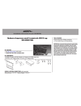
• ISO DDIN radio provision
• Painted matte black
• Relocates the factory climate control and switches
• Parts included to modify the factory airbox
• A) Radio trim panel • B) Back up housing • C) Radio brackets • D) Climate and switch panel housing
• E) Airbox cover • F) Cutting template • G) Climate bracket • H) Actuator arm • I) (1) #6 x 1/2” Phillips screw
• J) (4) #8 x 1/2” Phillips screws • K) (2) #8 x 3/8” Phillips screws • L) (2) panel clips • M) Vent door
KIT FEATURES
KIT COMPONENTS
WIRING & ANTENNA CONNECTIONS (sold separately)
Wiring Harness: • 70-8590 • 70-9003 (nav models 02-06)
Antenna Adapter: • 40-VW10 40-EU10 (nav models 02-06)
• Panel removal tool • Phillips screwdriver • Pick tool
TOOLS REQUIRED
BMW 3-Series 1999-2005,
3-Series
(coupe, convertible) 2006, M3 2001-2006
(for factory switch panel with one long opening)
95-9313B
A
C
G I JH
D E
K L M
B
Dash Disassembly ..............................................2-5
Sub-dash airbox modifications ..........................6-9
Kit Assembly
– ISO DDIN radio provision .................................... 10
Climate and Switch Panel Assembly .................. 11
Table of Contents
F

95-9313B
2
Dash Disassembly
1. Unclip and remove the trim panel
above the glove box. (Figure A)
2. Unclip and remove the trim panel
above the factory radio. (Figure B)
3. Remove (2) Phillips screws
securing the radio and then unplug
and remove the radio. (Figure C)
Continued on the next page
(Figure A) (Figure C)(Figure B)

95-9313B
(Figure D)
4. Unsnap and remove the climate
control panel. (Figure D)
5. Pull straight up on the shift knob to
remove. (Figure E)
6. Unclip and remove the boot around
the shift selector. (Figure F)
Continued on the next page
3
Dash Disassembly
(Figure E) (Figure F)

95-9313B
4
Dash Disassembly
7. Remove (2) Phillips screws
securing the shift selector trim
panel, and then unclip and remove
the panel. (Figure G)
8. Open the upper door on the lower
switch panel. Using a pick tool, or
something suitable, disengage (2)
clips in the upper corners of the
tray to remove the tray and door.
(Figure H)
(Figure G)
(Figure H)

95-9313B
9. Remove (4) Phillips screws now
exposed securing the lower switch
panel, and then unplug and remove
the panel. (Figure I)
Note: All of the switches
will need to be removed and
installed into the new switch
panel provided.
10. Remove (2) Phillips screws, and
then unclip and move aside the
vent assembly above the radio
opening. It is not necessary to
remove the assembly. But if
desired, there will be a cable
attached to the assembly that will
need to be removed. (Figure J)
11. For non-NAV equipped cars,
remove (2) Phillips screws
securing the plastic radio/climate
housing from the radio/climate
cavity, and then remove.
Continue to kit assembly
5
(Figure I) (Figure J)
Dash Disassembly

95-9313B
Sub-dash airbox modifications
6
1. Remove (4) metal retaining clips
holding the air box front panel in
place and remove the panel.
Note: One of the retaining clips
will be reused in step 7.
(Figure A)
2. Clip the cutting template over the
top edge of the air box, mark for
cutting, remove the template, then
and cut the marked area.
(Figure B)
Continued on the next page
(Figure A)
(Figure B)

95-9313B
7
Sub-dash airbox modifications
3. Remove the upper actuator arm
from the passenger vent door.
Remove the lower actuator arm
from the vent doors. Unclip the
passenger side first and then the
drivers side. (Figure C)
4. Remove the passenger side vent
door. Unclip from the bottom, then
push and rotate the top clip out of
the slot in the airbox. (Figure D)
Note: Remember the orientation
of the vent door arm (approx.
11:00) when removing to ease in
reinstallation.
Continued on the next page
(Figure C)
(Figure D)

95-9313B
8
Sub-dash airbox modifications
(Figure E)
(Figure F)
5. Replace the factory passenger side
vent door with the supplied vent
door. Rotate the vent door into the
upper slot and clip into the lower
socket. (Figure E)
6. Replace the factory actuator
arm with the supplied actuator
arm. Clip the drivers side in first
and then the passenger side.
Reconnect the upper actuator arm
to the passenger vent door.
(Figure F)
Continued on the next page

95-9313B
9
Sub-dash airbox modifications
7. Set the air box cover into place
and secure the right side with the
metal retaining clip removed in
step 1. Secure the left side with
the (1) #6 x 1/2” Phillips screw
supplied. (Figure G)
8. Metra recommends using tape
along the upper edge of the air box
cover where the cut was made.
Duct tape or A/C aluminum tape is
suggested. (Figure H)
Continue to kit assembly
(Figure G)
(Figure H)
Tape the shaded area
Clip
location
Screw
location

95-9313B
10
(Figure B)
(Figure C)(Figure A)
1. Attach the radio brackets to the
radio using the screws supplied
with the radio. (Figure A)
2. Attach the back-up housing to the
radio/bracket assembly with the (4)
#8 x 1/2” Phillips screws supplied.
(Figure B)
3. Locate the factory wiring harness
and antenna connector in the
dash, and complete all necessary
connections to the radio and
climate control panel. Metra
recommends using the proper
mating adapter from Metra and/or
AXXESS. Test the radio for proper
operation.
Note: After all testing has been
performed, disconnect the
climate control panel, relocate
the harness to the lower switch
panel area, and then proceed to
the next step.
Kit Assembly
4. Secure the completed assembly
into the radio/climate cavity using
the (2) #8 x 3/8 inch screws
supplied.
5. Secure the vent assembly to the
vehicle using the (2) factory Phillips
screws removed in step 10 of dash
disassembly.
6. Attach (2) panel clips provided
with the kit onto the radio trim
panel (Figure C), and then attach
the panel to the radio assembly.
Secure the assembly to the vehicle
using the (2) factory Phillips
screws removed in step 3 of dash
disassembly.
Continue to climate and switch
panel assembly

95-9313B
11
1. Secure the climate bracket onto
the top of the climate and switch
panel housing. (Figure A)
2. Secure the climate and switch
panel housing into the lower
dash opening with the (4) factory
screws removed in step 9 of dash
disassembly. (Figure B)
3. Connect all electrical connectors to
the climate control panel and then
snap the panel into the housing.
(Figure B))
4. Reassemble the dash in reverse
order of disassembly.
Climate and switch panel assembly
(Figure A)
(Figure B)

REV. 1/25/2017 INST95-9313B
KNOWLEDGE IS POWER
Enhance your installation and fabrication skills by
enrolling in the most recognized and respected
mobile electronics school in our industry.
Log onto www.installerinstitute.com or call
800-354-6782 for more information and take steps
toward a better tomorrow.
Metra recommends MECP
certified technicians
Installation instructions for part 95-9313B
METRA. The World’s best kits.
®
metraonline.com
© COPYRIGHT 2017 METRA ELECTRONICS CORPORATION
IMPORTANT
If you are having difficulties with the installation
of this product, please call our Tech Support line
at 1-800-253-TECH. Before doing so, look over
the instructions a second time, and make sure
the installation was performed exactly as the
instructions are stated. Please have the vehicle
apart and ready to perform troubleshooting
steps before calling.

INSTRUCCIONES DE INSTALACIÓN PARA LA PIEZA 95-9313B
METRA. The World’s best kits.
®
metraonline.com1-800-221-0932
© COPYRIGHT 2017 METRA ELECTRONICS CORPORATION
REV. 1/25/2017 INST95-9313B
¡PRECAUCIÓN! Todos los accesorios, interruptores,
paneles de control climático y especialmente las luces
indicadoras de bolsa de aire deben estar conectados
antes de encender el encendido. Además, no extraiga la
radio de fábrica con la llave en la posición de encendido,
o mientras el vehículo esté funcionando.
Indice
• Herramienta para quitar paneles
• Destornillador Phillips • Herramienta en punta
HERRAMIENTAS REQUERIDAS
CABLEADO Y CONEXIONES DE ANTENA
(se venden por separado)
Arnés de cables: • 70-8590 • 70-9003 (modelos nav 02-06)
Adaptador de antena: • 40-VW10 40-EU10 (modelos nav 02-06)
• Provisión de radio ISO DDIN
• Pintura negra mate
• Reubica el control del clima de fábrica e interruptores
• Partes incluidas para modificar la caja de aire de fábrica
• A) Panel de moldura de radio • B) Carcasa de respaldo • C) Soportes del radio • D) Carcasa del clima y panel de interruptores
• E) Cubierta de la caja de aire • F) Plantilla de corte • G) Soporte del clima • H) Brazo accionador • I) (1) tornillo Phillips #6 de
1/2” • J) (4) tornillos Phillips #8 de 1/2” • K) (2) tornillos Phillips #8 de 3/8” • L) (2) ganchos para panel • M) Puerta de la rejilla
CARACTERÍSTICAS DEL KIT
COMPONENTES DEL KIT
BMW 3-Series 1999-2005,
3-Series
(cupé, convertible) 2006, M3 2001-2006
(para panel de interruptores de fábrica con una abertura larga)
95-9313B
A
C
G I JH
D E
K L M
B
F
Desmontaje del tablero ......................................... 2-5
Modificaciones a la caja de aire del sub tablero . 6-9
Ensamble del kit ...................................................... 10
Ensamble del panel de interruptores y del clima ..11

95-9313B
Desmontaje del tablero
2
1. Desenganche y quite el panel
de la moldura que está sobre la
guantera. (Figura A)
2. Desenganche y retire el panel de
moldura que está arriba del radio
de fábrica. (Figura B)
3. Quite los (2) tornillos Phillips que
sujetan el radio, luego desconecte
y quite el radio. (Figura C)
Continua en la siguiente pagina
(Figura A) (Figura C)(Figura B)

95-9313B
3
Desmontaje del tablero
(Figura D)
4. Desenganche y quite el panel del
control de clima. (Figura D)
5. Jale directamente hacia arriba
la perilla de la palanca de
velocidades para quitarla.
(Figura E)
6. Desenganche y quite la cubierta
que rodea el selector de la palanca
de velocidades. (Figura F)
Continua en la siguiente pagina
(Figura E) (Figura F)

95-9313B
4
Desmontaje del tablero
7. Quite los (2) tornillos Phillips que
aseguran el panel de la moldura
del selector de la palanca de
velocidades y luego desenganche
y quite el panel. (Figura G)
8. Abra la puerta superior en el
panel de interruptores inferior.
Con una herramienta en punta
o algo adecuado, desenganche
los (2) ganchos en las esquinas
superiores de la bandeja para
quitar la bandeja y la puerta.
(Figura H)
Continua en la siguiente pagina
(Figura G)
(Figura H)

95-9313B
Desmontaje del tablero
9. Quite los (4) tornillos Phillips
ahora expuestos que sujetan el
panel de interruptores inferior,
luego desconecte y quite el panel.
(Figura I)
Nota: todos los interruptores
deberán quitarse e instalarse en
el nuevo panel de interruptores
suministrado.
10. Quite los (2) tornillos, luego
desenganche y haga a un lado
el ensamble de rejillas que está
arriba de la abertura del radio. No
es necesario quitar el ensamble.
Pero si lo desea, habrá un cable
conectado al ensamble que deberá
quitar. (Figure J)
11. Para vehículos sin equipamiento de
NAV, quite los (2) tornillos Phillips
que sujetan la carcasa de plástico
del clima/radio de la cavidad del
clima/radio y luego quítela.
Continua en modificaciones a la
caja de aire del sub tablero
5
(Figura I) (Figura J)

95-9313B
Modificaciones a la caja de aire del sub tablero
6
1. Quite los (4) ganchos de retención
de metal que sostienen el panel
frontal de la caja de aire en su
lugar y quite el panel.
Nota: uno de los ganchos de
retención se volverá a usar en el
paso 7. (Figura A)
2. Enganche la plantilla de corte
sobre el borde superior de la caja
de aire, marque el corte, quite
la plantilla y luego corte el área
marcada. (Figura B)
Continua en la siguiente pagina
(Figura A)
(Figura B)

95-9313B
7
3. Quite el brazo accionador superior
de la puerta de la rejilla del
pasajero. Quite el brazo accionador
inferior de las puertas de la rejilla.
Desenganche primero el lado
del pasajero y luego el lado del
conductor. (Figura C)
4. Quite la puerta de la rejilla del
lado del pasajero. Desenganche
desde abajo, luego oprima y rote el
gancho superior fuera de la ranura
en la caja de aire. (Figura D)
Nota: recuerde la orientación del
brazo de la puerta de la rejilla
(aprox. 11:00) al quitar para
facilitar la reinstalación.
Continua en la siguiente pagina
(Figura C)
(Figura D)
Modificaciones a la caja de aire del sub tablero

95-9313B
8
(Figura E)
(Figura F)
5. Reemplace la puerta de la rejilla de
fábrica del lado del pasajero con
la puerta de la rejilla provista. Rote
la puerta de la rejilla dentro de
la ranura superior y enganche al
tomacorriente inferior. (Figura E)
6. Reemplace el brazo accionador
de fábrica con el brazo accionador
provisto. Enganche primero el
lado del conductor y luego el lado
del pasajero. Vuelva a conectar el
brazo accionador superior de la
puerta de la rejilla del pasajero.
(Figura F)
Continua en la siguiente pagina
Modificaciones a la caja de aire del sub tablero
/