Page is loading ...

Installation Instructions for Backwashing Systems with Fleck
5600 and 5600SXT
Covers all standard backwashing systems, including arsenic systems, carbon tanks,
iron filters, pH tanks, and sediment tanks.
THANK YOU
Thank you for purchasing a new Backwashing System from Premier Water
Systems. We appreciate the opportunity you have given us to provide you
with better water. We are committed to providing the best customer
experience possible and have provided these installation instructions to
make things as simple as possible. If you have read through these entire
instructions and FAQ section and still have questions feel free to contact
us for further help. Our office hours are Monday-Friday 10:00 AM - 4:00
PM PST, and you can call us at 661-575-0033.
BEFORE YOU BEGIN
• BASIC PLUMBING SKILLS ARE REQUIRED FOR INSTALLATION. IF YOU ARE UNSURE OF YOUR
ABILITIES TO INSTALL THE SYSTEM USING THESE INSTRUCTIONS PLEASE HIRE A QUALIFIED
PLUMBER.
• READ THROUGH YOUR PARTS LIST AND VERIFY ALL COMPONENTS ARE ACCOUNTED FOR AND
IN GOOD CONDITION BEFORE SCHEDULING A PLUMBER.
• PLEASE READ THROUGH THE ENTIRE INSTRUCTION MANUAL CAREFULLY. IF HIRING A
PLUMBER ENSURE THEY HAVE A COPY BEFORE THEY START.
• MOST COMMON QUESTIONS ARE ANSWERED IN THE INSTRUCTIONS OR FAQ SECTION. IF
YOU HAVE READ BOTH OF THOSE AND STILL HAVE QUESTIONS YOU MAY CONTACT US FOR
FURTHER HELP.
• PLUMBING RELATED QUESTIONS NEED TO BE DIRECTED TO A LOCALLY QUALIFIED PLUMBER.
WE ARE NOT PLUMBERS AND ANY PLUMBING QUESTIONS WE RECEIVE WILL NOT BE
ANSWERED.

SYSTEM REQUIREMENTS
Your chosen installation location and water supply must meet ALL of the following
requirements:
• 20-90 PSI (1.38-6.20BAR)
• 34-110°F (1.1-43.3°C)
• System must be protected from freezing
• Firm level surface AFTER the pressure tank
• 3-prong, 120V outlet within 5 ft. (1.5 m) of the control head with constant
power. GFCI outlet is recommended. Use of an extension cord is NOT
recommended.
• A 1.5-inch standpipe, sump pit, or outside drain. Please note: The drain line
is pressurized and can be ran vertically if necessary.
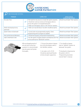
1. VERIFY SYSTEM INVENTORY
Use the following table to help verify the parts that are included with your system
and verify that they are all accounted for. Inspect all parts for damage and report
any damage immediately. Damage claims must be made within 7 days of
delivery to be eligible for replacement.
Depending on system size you can see what tank size and media amounts you will
receive:
System Size
0.5 ft³
0.75 ft³
1 ft³
1.5 ft³
2 ft³
2.5 ft³
3 ft³
3.5 ft³
Tank (in
inches)
8 x 44
8 x 44
9 x 48
10 x 54
12 x 52
13 x 54
14 x 65
14 x 65
Gravel/Garnet
10 lb.
10 lb.
12 lb.
16 lb.
20 lb.
35 lb.
50 lb.
50 lb.
Media
0.5 ft³
0.75 ft³
1 ft³
1.5 ft³
2 ft³
2.5 ft³
3 ft³
3.5 ft³
Tank Size and Media Qty

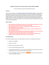
Polyglass Tank
A tall slender tank 44–65 inches in
height with an opening on the top.
Larger tanks may have a gray
threaded adapter to reduce tank
opening to match control
head. Please Note: If you have the
Vortech tank upgrade, the Vortech
tank replaces the standard tank, so a
system with the Vortech tank
upgrade will still have only one
polyglass tank.
Note for loaded systems: Tanks that
are shipped loaded may arrive on
their side or even upside down. The
tanks are closed and the media will
return to the bottom once place in
the correct position. Any mixing of
tank contents will correct itself after
being placed in service.
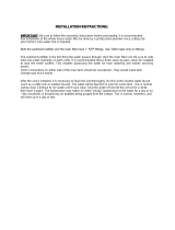
Riser/Distributor Tube
A tall pipe that runs from the bottom
of the tank to the control valve. If
your tank is loaded (empty tanks only
weigh 20-30 pounds) DO NOT pull the
riser tube out of the tank. One end
has a basket (basket design varies)
and it usually ships inside the tank.
Please Note: On systems with the
Vortech tank there is no basket as the
pipe is connected to the bottom tank
plate and is not removable. (Tank
cutaway shown)
__________________________________________________________________
Control Head
Screws on top of the tank and controls the water flow and backwashing cycles.
Digital SXT has LCD panel. The mechanical has control knobs.
Please note: Some SXT systems may have labels referring to the older SE model
number. This is an internal designation and does NOT indicate that you received
an SE controller. This image will show the differences for easy reference.

____________________________________
Bypass Valve
Depending on your order your system will have either a single piece stainless
steel bypass or a two part plastic bypass with yoke connection. This is what
connects to your control head and provides standard fitting connections to hook
up to your plumbing.
___________________________________________________________________
Drain Fitting
Fitting(s) that connect the control
head to the drain line. Please Note:
Drain line is not included. Depending
on the system ordered there are
multiple options, and the pictures
shown are common examples but
actual fitting may vary.
Before you start plumbing
1. PRE-INSTALLATION PREPARATION
Money-saving tip: If hiring a plumber to do the installation you can save some
money by preparing the tank ahead of time. This cuts down on the time the
plumber has to spend and doing so is simple enough that most people can
accomplish it in less than an hour.

1. Verify riser tube position
**Most of our systems are sent out Pre-Loaded so this step can be skipped
NOTE REGARDING LOADED TANKS: Systems that arrive loaded will have the riser
tube in place and attempting to remove it will require the tank to be emptied and
refilled. DO NOT try to remove the riser tube from a loaded tank.
The riser tube sits in an indentation centered in the bottom of the tank. With the
riser tube properly positioned, ensure that it is within 1/3 inch (8 mm) above or
below the lip of the tank. If it is not contact us for help correcting the problem.
For tanks that were not loaded or Partially loaded:
1. Load media and gravel—gravel goes in first
Make sure to cover the opening of the riser tube. Simply put something over the
end of the tube such as a piece of tape, to prevent anything from falling into the
riser tube.
If you have gravel with your system it will go in first!
Please note: MOST systems upgraded with a Vortech Tank do NOT require gravel.
With some medias (such as Filox/Mang-Ox) gravel is still required for the best
results, so if you have gravel, use it. Make sure to empty all boxes to verify it is
not in the bottom of the tank box or in a box with the media.
When filling the tank, do so slowly and ensure the riser tube stays correctly
positioned and centered in the tank. If you have more than one bag of media,
after gravel the order does not matter and all of it should be used. Once all the
media is loaded the tank will not be completely full, this is normal.
2. Finish filling tank with water Optional
Once the media is loaded you may finish filling the tank with water. Allow media
to soak for 12-24 hours. This can help reduce air bubbles, reduce initial flush time,
and ease initial startup.

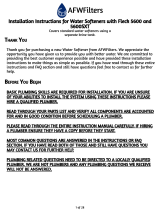
ATTACH THE CONTROL HEAD
Lubricate the O-rings DO NOT use Vaseline
The tank O-ring—Image 4—seals the control valve to the tank, and the pilot O-
ring—Image 5—seals around the riser tube. Verify they are present and free from
nicks or kinks. Use a silicone lubricant or vegetable oil to both O-rings. DO NOT
use petroleum based lubricants!
Please note that the pilot O-ring is up inside the control head and you will
usually have to reach up inside to feel it. It is very secure inside the head and
almost impossible for it to come out. It is also a good idea to verify that the riser
tube fits snugly into the pilot hole and that the O-ring seals around it.
image 4 image 5
3. Inspect and install top distributor basket if applicable (We use downflow
systems – Upper basket NOT NEEDED)
Depending on system
configuration your system may
include a top distributor
basket—. If your system
includes one it is
recommended that you use it.
If you do not have one
then it is not needed. If you
do have one the larger end will
fit inside the bottom of your
control valve, with the smaller
end sliding over the riser tube

pointing down into the tank—.
Please note that locking tabs
hold it in place so a fair amount
of force is needed to install or
remove it.
4. Screw on control head hand tight only
DO NOT apply anything (pipe dope, plumbers paste, Teflon tape, etc.) to the threads on the
control head or the resin tank!
Ensure the riser tube slips inside the pilot opening in the bottom of the head. Screw the head
down onto the resin tank until solid contact is made between the tank and O-ring, then tighten
about another 1/4–1/3 of a turn and STOP. Do not over tighten the control head as this can
cause damage. Once properly tightened down check to ensure the tank and control head
meet evenly all the way around.
SETUP CONTROL HEAD
Plug control head in
Plug the control head into a qualifying outlet as stated in the requirements section. Please
Note: The control head can be plugged in and operated without water, this will not damage
the control head. Once plugged in, verify the system is receiving power and ensure the outlet
is not on a switch that might get turned off. On digital valves the display should light up and
start flashing a time, on mechanical valves you may hear a quiet hum of the motor or you may
have to wait to see if the time dial keeps track of time. Please note: The service icon (the icon
that looks like a faucet) indicates that the system is IN SERVICE, that is the system is running
and working. It DOES NOT indicate the system needs serviced.
1. DIGITAL CONTROLLER - Inital valve setup
If you have the mechanical valve skip the digital controller sections and proceed with the
mechanical setup

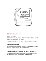
For initial programming enter master programming by setting the clock to 12:01 pm. To set
the time of day press and hold the up OR down arrow until the service icon is replaced with
the programming icon. Use the up and down arrows to set the time of day (PM is indicated in
the upper right corner of the screen). Hold the arrow button to advance quickly through the
time. Once the time is set, press the extra cycle button to save the setting. Once the
parameter display is gone, press and hold the up AND down arrow buttons together for 5-10
seconds until the programming icon appears and [DF] is shown in the parameter code. Once
each setting has been entered, use the extra cycle button to advance to the next setting.
Please Note: Most of these settings will be left alone.
Depending on your system some settings may not be shown, and some settings may be
different than shown here. Do not change any settings unless specifically instructed to do so
by these instructions or one of our techs.

SXT Master Programming Chart
Ensure the time is set to 12:01pm, hold BOTH up and down arrows until programming icon appears
Required
This setting is required and should be changed if it does not match
Variable
This setting will vary depending on the system and application. Use these instructions to set
appropriately.
PLEASE NOTE:
Any setting on your system that is not specifically highlighted below will be left at default. This is a list of all
possible options, and many will NOT be shown on your system and are included for informational purposes
only.
Code
Parameter
Options
Description
DF
Display Format
GAL
Volume is displayed in gallons and time in a 12-hour AM/PM format - These instructions are
based on the GAL setting
Ltr
Volume is displayed in liters and time in 24-hour format
VT
Valve Type
dF1b
Downflow single backwash - used on softeners that require the brine draw.
Fltr
Filter - used for basic backwashing systems that do not need the brine draw
dF2b
Downflow double backwash - similar to the dF1b but with 2 backwashes. Not commonly
used.
UFbd
Upflow brine first - not commonly used.
UFtr
Uplow filter - not commonly used.
Othr
Other - not commonly used
CT
Control Type
FI
Metered (Flow) Immediate - counts down from the programmed gallon capacity and begins
a backwash immediately after reaching 0. Only used on dual tank water softeners.
Fd
Metered (Flow) Delayed - counts down from the programmed gallon capacity and when 0 is
reached queues a backwash cycle for the set regeneration time. Only used on water
softeners.
Tc
Time Clock - will begin a backwash cycle at the set regeneration time after the set number
of days has passed. Common setting on all backwashing systems except water softeners to
ensure consistent cleaning of the media.
dAY
Day of the Week - will begin a backwash cycle on the set day(s) at the set regeneration
time. More consistent Time Clock setting is recommended in most situations.
NT
Number of
Tanks
1
For systems with only 1 media tank (all systems except dual tank softeners).
2
For systems with 2 media tanks (dual tank softeners only).
UT
Indicates
current tank in
service
U1
Tank 1 is in service
U2
Tank 2 is in service (dual tank softeners only).
C
Capacity
1-999.9
(x1000)
System capacity, in grains. Metered softeners only.
H
Hardness
1-199
Hardness of the water, in grains. Metered softeners only.
RS
Reserve
Selection
SF
Percentage saftey factor - this uses a percentage of the capacity for a reserve. Softener
systems only.
rc
Fixed reserve capacity - uses a set volume for a reserve. Softener systems only.
SF
Saftey Factor
0-50%
Only applies to softeners with RS set to SF
RC
Reserve
Capacity
1-(half of
calculated
capacity)
Fixed reserve capacity, softeners only. It is commonly set to the average number of gallons
used in a day. If you are unsure of your actual usage, a good rule of thumb is to set it to the
number of people in the house times 75. Example, if there are 4 people in the house, you
would set it to 300 gallons (4x75).

DO
Day Override
3
This setting will start the backwash cycle after the set number of days. Typically set to 3 or
less to ensure the media gets lifted and cleaned off regularly. This ensures effective
filtration and long media life. If you have very dirty water or use large volumes of water you
will want to set this to 1 or 2.
RT
Regen Time
12:00
This sets the time that the backwash cycle will start. This process can take up to 2 hours
depending on system size and configuration, so schedule it when water will not be used. It
is common to set to run when everyone is asleep or out of the house, and ensure it does
not conflict with any other systems you may have.
BW
Backwash
10
This sets the length of the backwash portion of the cycle. During this cycle water flows
through the system in reverse to lift the media and rinse off accumulated contaminants,
with a strong flow of water going out the drain line. Reducing this cycle can lead to reduced
media life and premature system failure. For very dirty water longer times may be needed.
BD
Brine Draw
N/A
This sets the length of the brine draw portion of the cycle. Standard backwashing systems
do not use this setting and typically it will not show.
RR
Rapid Rinse
10
The rapid rinse cycle runs water through the tank in the normal direction to settle the
media for normal operation. During this cycle there will be a steady flow of water down the
drain.
BF
Brine Fill
N/A
This sets the length of the brine fill portion of the cycle. Standard backwashing systems do
not use this setting and typically it will not show.
D1-D7
Day of the
Week Setting
OFF
Set to On or OFF for each day of the week. Only applies to systems with Control Type day,
not typically used.
CD
Current Day
1-7
Used to set the current day. Only applies to systems with Control Type day, not typically
used.
FM
Flow Meter
Type
(metered
systems only)
P0.7
3/4" Paddle Wheel Meter
Gen
Generic or Other Meter
P2.0
2" Paddle Wheel Meter
t1.5
1.5" Turbine Meter
P1.5
1.5" Paddle Wheel Meter
t1.2
1.2" Turbine Meter
t1.0
1" Turbine Meter
P1.0
1" Paddle Wheel Meter
t0.7
3/4" Turbine Meter
K
Meter Pulse
Setting
0.1-999.9
Pulses per gallon. Only applies to systems with FM set to Gen, not typically used.
Pressing the extra cycle button after the final setting will save your changes. If no buttons are pressed for 60 seconds while in
programming mode the changes will be cancelled.
If you accidentally change a setting that does not have a recommended or variable value: Please do a hard reset as outlined in
the resets section to return all values to default. You can then go back through the programming to set it up according the the
chart above.
SXT Master Programming Chart
Once you have finished programming use the arrows to set the current time of day. Once the
time is set the display should then show the service icon, with the data display flashing
between the current time of day and days remaining until the next backwash. Once it reaches
0 the system will queue a backwash for the set time. A flashing service icon indicates that a
backwash is queued. A manual backwash can be queued by pressing the extra cycle button. An
immediate backwash can be initiated by holding the extra cycle button for about 5
seconds. The service icon indicates that the system is "In Service" and functioning correctly,
it does NOT mean that the system needs service.

After initial setup the master programming should not need to be used again unless a system
reset is performed. Even in the event of a power outage all settings are retained. If your water
use or water quality changes you can use the user programming to make common changes to
the programming as lined out below.
SXT User Programming Chart
Ensure the time is NOT set to 12:01pm, hold BOTH up and down arrows until programming icon appears
Please refer to the master programming chart for proper values each setting.
Code
Parameter
Options
Description
DO
Day Override
3
This setting will start the backwash cycle after the set number of days.
RT
Regen Time
2:00
This sets the time that the backwash cycle will start.
CD
Current Day
1-7
Sets the current day (day of week systems only)
Pressing the extra cycle button after the final setting will save your changes. If no buttons are pressed for 60 seconds while in
programming mode the changes will be cancelled.
SXT User Programming Chart
1. DIGITAL Controller - Resets
If your controller is showing odd behavior such as erratic display, no display, or showing an
error code, the first step is to try and reset it. Start with the soft reset, and if that does not
solve the problem move on to the master reset. If the problem persists contact one of our
technicians.
Reset
Directions
Effect
Soft
Reset
Hold Extra Cycle and
Down buttons for 25
seconds
This will reset all parameters to the system default values, but leaves the days since the last
backwash intact. This is a good place to start if you feel you may have changed a default setting.
After resetting proceed through the master programming section.
Hard
Reset
Hold Extra Cycle button
while plugging the unit
in
This will reset all parameters in the system. This is typically reserved for erratic behavior that a
soft reset does not resolve. After resetting proceed through the master programming section.
SXT Controller Resets
MECHANICAL CONTROLLER - Frequency
To set the backwash frequency, there is a ring of day tabs numbered 1 - 12 on the system.
Each tab can be either inward towards the middle of the ring (inactive) or outward away from
the middle of the ring (active). To set up your system, simply slide the tabs out on the days you
want it to backwash. For example, to backwash every 3 days (the minimum requirement for
most backwashing systems) simply slide the tabs numbered 3, 6, 9, & 12 to their outward
active position. Depending upon your water usage and contaminate level, you may need to
backwash more frequently. To backwash every 2 days (every other day) slide the tabs

numbered 2, 4, 6, 8, 10, & 12 to the outward active position, to backwash every day push all
tabs to their outward active position
MECHANICAL CONTROLLER - Time
To set the time, locate the 24-hour time gear (the large gear located behind the manual cycle
knob) and note the current time arrow. Push the red time set button in and rotate the 24-hour
time gear until the current time arrow lines up with the current time of day. The red arrow
inside the day tab ring indicates the current day, if the arrow is pointing toward an active tab
the system will run a backwash cycle that night at midnight or 2 AM (depending on the system,
the time is usually indicated on a label located on the back of the valve). During backwash
there should be no water being used, and the default time is usually fine for most homes. To
have it run at a different time (for example if you work late and are up and using water at the
default time) you will need to adjust the current time of day to trick the system into doing so
at the desired time. For example: if the system is set to run at 2 AM and you want it to run at 8
AM, set the current time of day 6 hours behind, that way the system will think it is 2 AM when
it is actually 8 AM.
Plumbing the system in
1. PLUMBING GUIDELINES
Before you continue Many homeowners install their own water systems with basic
plumbing skills; if you are not comfortable with projects like this, please hire a
professional plumber. Make sure to check local plumbing codes and follow any codes
that apply. These instructions offer basic plumbing tips and cannot cover every
situation. They are intended as a supplement and should not replace local plumbing
codes or actual plumbing experience.
1. Drain Line Connection
Please note: Drain water comes out under line pressure, so it can be run vertically
to connect to an overhead drain pipe.

Never make a direct connection into a waste water drain. A physical air gap of at least 3
inches (76 mm) between the end of the drain line and the wastewater level in the drain pipe
should be used to avoid contamination of the line. An additional gap of 3/4 inch (19 mm)
between the drain pipe and drain line is recommended to prevent any problems in the case of
a pipe overflow. Using a simple P-trap as shown——is ideal as well, but a stand pipe with a
diameter of at least 1.5 inches (38 mm) is adequate. As the water coming out is under
pressure, make sure to secure the drain line so that it does not move and create a mess.
Do not tie multiple systems into a single drain line.
If hooking up multiple systems, each system needs a separate, independent drain line to
ensure proper operation and prevent damage. Systems can all be run to the same
standpipe/sump/outside drain, but the drain line from each system needs to be separate.
Do not use additional fittings on the drain line.
Avoid installing any additional fittings (check valves, ball/gate valves, etc.) as this can prevent
proper backwash and cause premature system failure.
1. Inlet/Outlet Connections
Do not overtighten the screws. The bypass valve will have some up and down movement,
this is normal. The clips simply hold the connection fittings together and the screws only need
tightened enough to keep the clips in place. Further tightening will not stop leaks and
tightening too much can damage the system, which will not be covered under warranty.

Verify flow direction. Untreated water will enter the system on
the side marked with an arrow pointing toward the front of the
control head (on both the bypass valve and the control head
itself). Treated water will exit the system on the side marked
with an arrow pointing away from the front of the control head
(on both the bypass valve and the control head itself).
Correct inlet/outlet connections are vital. Improper flow
direction will prevent proper operation and can damage your
system and your plumbing. The direction of flow cannot be
changed. Turning the bypass upside down will not change the
direction of the water flow.
It is recommended to keep the bypass in the service position when making plumbing
connections and turn it to bypass when first turning the water back on. shows the bypass
position. In bypass position the handles will be turned 90-degrees and be perpendicular to the
inlet and outlet fittings.
When soldering do not solder directly to the included connection or
close to the control head. First solder a short (min 3-inch [7.6-cm])
piece of copper pipe onto the adapters, away from the valve, before
connecting the adapter to the bypass or yoke fitting.
For threaded connections, do NOT tighten the adapters into fittings
while they are connected to the control head. Disconnect the
bypass or yoke fitting, and connect the adapter using a high-quality
thread sealant (pipe joint compound or Teflon/PTFE tape), and
replace.
When installed the bypass valve can move up and down, this is normal.
1. PLACE SYSTEM IN SERVICE
Once all plumbing is done and plumbing connections have been checked for leaks you can
place the system in service.
2. Open bypass valve slowly
If you have more than one system, ensure the other systems are bypassed to prevent any
possible problems. Open a faucet that is near the system, a laundry sink or outside faucet (if it
will be treated by the system) is ideal, this will allow the air to bleed out of the

system. Slowly open up the bypass valve just to the point of allowing water to enter the
system at a trickle, and leave it like that until the tank is full of water. If you prefilled the
system it should only take a minute or two. Once the tank is full, slowly open the bypass valve
the rest of the way. Allow water to run out of the faucet for 15-20 minutes to ensure all the air
is worked out of the tank and off of the valve, then close the faucet.
1. Check for leaks
Check the system for any leaks, paying attention to the seal between the tank and control
head as well as the connections between the bypass valve and control head. Open a nearby
faucet and check to ensure there is no leaks that show up when water is running.
1. Flush the system
Open a nearby faucet. The water may be discolored at first, this is normal. Let water run out of
the faucet for at least 10 minutes, or until any discoloration clears up. Depending on the
system this may be almost immediate, or it may take a couple of hours. Once the water is
cleared up a manual backwash should be run.
1. Initiate manual backwash
It is a good idea to allow the system to run through a manual cycle. On mechanical valves, turn
the main knob until it clicks into the first position. On digital systems, hold the extra cycle
button for 5-10 second until the backwash starts.
1. Verify proper operation
Watch the system as it steps through each cycle, make sure it moves to each position, that
water is not leaking from any other fittings, and that water is flowing down the drain line.
Be sure to return any other systems to the service position.

Frequently Asked Questions
INVENTORY AND SETUP
What is the proper order to arrange multiple systems?
If you are installing more than one tank system the typical order for installation is:
sediment filter > pH filter > iron filter > carbon filter > water softener > arsenic filter
Whole house cartridge systems are typically installed after any tank systems, the Scale Sentry
system after the cartridge system(s), and any UV systems will be last.
Do I need a prefilter?
In most cases a prefilter is not necessary. Since the system cleans itself most particulate in the
water will be trapped and rinsed off by the backwash cycle, eliminating the need for a
sediment prefilter.
My polyglass tank arrived and sits crooked, what do I do?
The black boot on the bottom of the tank may get knocked out of alignment during shipment.
If your tank is a bit tilted, simply pick the tank up 2–3 inches (5–8 cm) off the floor and drop it
gently but firmly down, favoring the side that needs to be adjusted to make the tank stand
straight.
I have read or seen that I shouldn't install the top distributor basket, is that true?
**We use downflow systems, in downflow systems an upper basket is NOT NEEDED.
Information For Upflow Systems: The top distributor basket is used to help prevent media
from getting up into the control head and into your pipes, it also keeps the resin from going
down the drain during water or air surges. While systems that are installed correctly and
functioning properly will not have issues, the top basket is included as a safety measure to
prevent problems and it is recommended to use it if present. Those who recommend leaving it
off usually do so to prevent buildup on that basket that can lead to flow restrictions (more
common in high iron waters), but it is usually easier to clean or replace a top basket
periodically than cleaning out clogged fixtures if something does go wrong.
After installing the bypass, it still moves up and down, is that normal?
Yes. The bypass seals with O-ring and even when tightened down some movement will occur,
without leaking. The system requires this movement to allow for pressure changes in the
system. Do not overtighten the bypass valve. As long as the screws are snug enough to keep
the bypass from coming apart further tightening will just cause damage.

DRAIN LINE
Can I run my drain line to a sewer/septic?
Yes. These systems can be ran to your sewer or septic line and is typically the recommended
place to run the drain. Most concerns are related to the amount of water going down the
drain, and a properly designed septic/sewer system will not have a problem handling it.
Can my drain line be ran vertically?
Yes. Water from the drain comes out under pressure and can be ran vertically if needed.
DIGITAL DISPLAY
Why does my display flashing between the time of day and a number?
This is normal, with the number displayed indicating the number of days until the next
backwash.
What does the faucet icon mean?
That is the service icon, meaning the system is in service. It does NOT mean the system needs
service. If it is flashing then a backwash is queued for the next set time.
What does the water drop icon mean?
That is the flow icon. Only used on metered softeners, it indicates water is flowing through the
system.
What does the circled exclamation icon mean?
That indicates an error. Match the number on your display with the number on the error chart
below for troubleshooting tips.

SXT Error Codes
Error
Code
Error Type
Cause
Solution
0
Cam
Sense
Error
Piston took more
than 6 minutes to
advance
Unplug the system, disconnect the piston from the motor/gear, and
verify that the piston moves freely inside the valve; if it does not
replacement of the seal and spacers and possibly the piston is
required. After reconnecting the piston, inspect the control head
for any broken, worn, or disconnected parts, and replace or
reconnect any that are found. Perform a hard reset. After verifying
programming run the system through a backwash and watch the
motor to ensure that it is moving the piston, if it is not the motor
needs to be replaced. If error still occurs contact us for support.
1
Cycle
Step Error
Unexpected cycle
input
Unplug the system and check to ensure all electrical connections
and cam switches are secure. Plug the unit back in and check the
master programming and ensure valve type and system type are
correct for your system. Initiate a manual regeneration and verify it
progresses through the steps correctly. If error reoccurs, contact us
for support.
2
Regen
Failure
More than 99 days
since last backwash
(7 on day of the
week setups)
Perform a manual backwash to reset the error. Check your settings
to ensure the system is setup to backwash automatically. Check the
meter to ensure it is not stuck and that the gallons remaining is
counting down.
3
Memory
Error
Circuit board
memory failure
Perform a hard reset and go through the master programming to
update the settings. If error occurs again contact us for support
UD
Upper
Drive
Sync
Piston is syncing
Common when changing programming or if system looses power.
System will automatically recover from this state.
/