Page is loading ...

WARNING
If the information in these instructions is not followed exactly a fire or explosion may result causing, ,
property damage personal injury or death, , .
–Do not store or use gasoline or other flammable vapors and liquids in the vicinity of this or any other
appliance.
–WHAT TO DO IF YOU SMELL GAS
●Do not try to light any appliance.
●Do not touch any electrical switch do not use any phone in your building; .
●Immediately call your gas supplier from a neighbor s phone Follow the gas supplier s instructions’ . ’ .
●If you cannot reach your gas supplier call the fire department, .
–Installation and service must be performed by a qualified installer service agency or the gas supplier, .
–The installation must conform with local codes or in the absence of local codes the National Fuel Gas, ,
Code ANSI Z223 1 NFPA 54 and or CSA B149 1 Natural Gas and Propane Installation Code, . / / . , .
–When applicable the installation must conform with the Manufactured Home Construction and,
Safety Standard Title 24 CFR Part 3280 and or CAN CSA Z240 MH Series Mobile Homes, , / / , .
H
Keep this manual near this boiler for future reference
whenever maintenance or service is required.
NCB-210E
NCB-240E
Installation Manual
Condensing Combi Boilers-
Model
NCB-150E
Model VC 100 (LP) COMBI
VC 120 (LP) COMBI
VC 140 (LP) COMBI

2
Requirements for the State of Massachusetts
NOTICE BEFORE INSTALLATION
This appliance must be installed by a licensed plumber or gas fitter in accordance with the Massachusetts Plumbing and Fuel Gas
Code 248 CMR Sections 2 00 and 5 00. . .
IMPORTANT In the State of Massachusetts 248 CMR 4 00 5 00: ( . & . )
For all side wall horizontally vented gas fueled equipment installed in every dwelling building or structure used in whole or in part for,
residential purposes including those owned or operated by the Commonwealth and where the side wall exhaust vent termination is less than,
seven 7 feet above finished grade in the area of the venting including but not limited to decks and porches the following requirements shall( ) , ,
be satisfied:
1. INSTALLATION OF CARBON MONOXIDE DETECTORS At the time of installation of the side wall horizontal vented gas fueled equipment. ,
the installing plumber or gasfitter shall observe that a hard wired carbon monoxide detector with an alarm and battery back up is‐
installed on the floor level where the gas equipment is to be installed In addition the installing plumber or gasfitter shall observe that a. ,
battery operated or hard wired carbon monoxide detector with an alarm is installed on each additional level of the dwelling building or,
structure served by the side wall horizontal vented gas fueled equipment It shall be the responsibility of the property owner to secure the.
services of qualified licensed professionals for the installation of hard wired carbon monoxide detectors
a. In the event that the side wall horizontally vented gas fueled equipment is installed in a crawl space or an attic the hard wired carbon,
monoxide detector with alarm and battery back up may be installed on the next adjacent floor level‐ .
b. In the event that the requirements of this subdivision cannot be met at the time of completion of installation the owner shall have a,
period of thirty 30 days to comply with the above requirements provided however that during said thirty 30 day period a battery( ) ; , , ( ) ,
operated carbon monoxide detector with an alarm shall be installed.
2. APPROVED CARBON MONOXIDE DETECTORS Each carbon monoxide detector as required in accordance with the above provisions shall.
comply with NFPA 720 and be ANSI UL 2034 listed and IAS certified/ .
3. SIGNAGE A metal or plastic identification plate shall be permanently mounted to the exterior of the building at a minimum height of.
eight 8 feet above grade directly in line with the exhaust vent terminal for the horizontally vented gas fueled heating appliance or( )
equipment The sign shall read in print size no less than one half 1 2 inch in size. , ‐ ( / ) , GAS VENT DIRECTLY BELOW KEEP CLEAR OF ALL“ .
OBSTRUCTIONS”.
4. INSPECTION The state or local gas inspector of the side wall horizontally vented gas fueled equipment shall not approve the installation.
unless upon inspection the inspector observes carbon monoxide detectors and signage installed in accordance with the provisions of, ,
248 CMR 5 08 2 a 1 through 4. ( )( ) .

Contents 3
Contents
Safety Information 4
1 About the Boiler. 7
1 1 Items Included. 7
1 3. Specifications 8
1 4. Components 9
1 5. Dimensions 11
1 6. Rating Plate 13
2 Installing the Boiler. 14
2 1 Choosing an Installation Location. 14
2 2. How to Install 15
3 Installing the System Piping. 16
3 1 Installing a Space Heating System. 16
3 2 Installing a Domestic Hot Water DHW System. ( ) 18
3 3 Condensate Discharge. 20
3 4. Installing a Space Heating System 20
4 Connecting the Gas Supply. 21
4 1 Gas Pipe Sizing Tables. 21
4 2 Measuring the Inlet Gas Pressure. 23
5 Venting the Boiler. 24
5 1 Selecting a Vent Type. 24
5 2 Selecting Vent Pipe Materials. 28
5 3. Vent Terminal Installation Precautions 28
6 Setting the DIP Switches. 32
7 Connecting the Power Supply. 33
8 Installation Check list. 34
9 Operating the Boiler. 37
9 1 Turning the Boiler On or Off. 37
9 2 Adjusting the CH(Space Heating) Temperature. 37
9 3. Setting DHW Outlet Temperature mode 38
9 4. Setting FAN revolutions per minute (RPM) 38
9 5. Check the Hmode value 38
10 Appendixes. 39
10 1. Wiring Diagram 39
10 2. Component Assembly Diagrams and Parts Lists 40
5 4 Terminating the Vent. 29
1 2. Accessories 7

4 Safety Information
WARNING
If you do not follow these instructions exactly a fire or explosion,
may result causing property damage personal injury or loss of,
life.
This appliance does not have a pilot It is equipped with an.
ignition device which automatically lights the burner Do.
not try to light the burner by hand.
BEFORE OPERATING smell all around the appliance area for
gas Be sure to smell next to the floor because some gas is.
heavier than air and will settle on the floor.
WHAT TO DO IF YOU SMELL GAS
●Do not try to light any appliance.
●Do not touch any electric switch do not use any phone;
in your building.
●Immediately call your gas supplier from a neighbor s’
phone Follow the gas supplier s instructions. ’ .
●If you cannot reach your gas supplier call the fire,
department.
●Do not return to your home until authorized by your
gas supplier or the fire department.
Use only your hand to push in or turn the gas control knob.
Never use tools If the knob will not push in or turn by hand. ,
don t try to repair it call a qualified service technician’ , .
Force or attempted repair may result in a fire or explosion.
Do not use this appliance if any part has been under water.
Immediately call a qualified service technician to inspect
the appliance and to replace any part of the control system
and any gas control which has been under water.
Safety Information
The cautions issued by this installation manual include critical
information for the safety while using the product. When the
user fails to adhere to the following requirements can cause
For safety, according to the level of danger, we have indicated
by “DANGER”,“WARNING”,“CAUTION”and the definitions for
these terms are as follow
The definitions of the symbols indicated on the product and
installation manual are as follows
death, serious damages, and a great property loss.
DANGER
WARNING
CAUTION
When the required terms are not followed, it
indicates an urgent danger that may cause
death or serious bodily injury
When the required terms are not followed, it
indicates latent danger that may cause death
or serious bodily injury
When the required are not followed, it indicates
latent danger that may cause light injury or
semi-serious injuries

Safety Information 5
CAUTION
●Do not turn on the boiler unless the water and gas
supplies are fully opened.
Doing so may damage the boiler.
●Do not turn on the water if the cold water supply shut-
off valve is closed.
Doing so may damage the boiler.
●Do not use this boiler for anything other than its
intended purpose as described in this manual, .
●Do not remove the front cover unless the power to the
boiler is turned off or disconnected.
Failure to do so may result in electric shock.
●When servicing the controls label all wires prior to,
disconnecting them.
Failure to do so may result in wiring errors which can lead to,
improper or dangerous operation Verify proper operation.
after servicing.
●Do not use unapproved replacement or accessory parts.
Doing so may result in improper or dangerous operation
and will void the manufacturer s warranty’ .
●Do not place anything in or around the vent terminals,
such as a clothes line that could obstruct the air flow in,
or out of the boiler.
●This boiler has been approved for use in the USA and
Canada only.
Using the boiler in any other country will void the
manufacturer s warranty’ .
WARNING
●Do not store or use gasoline or other flammable liquids
near this boiler.
Doing so may result in fire or explosion.
●Do not place combustibles such as newspapers or,
laundry near the boiler or venting system, .
Doing so may result in a fire.
●Do not place or use hair sprays spray paints or any other, ,
compressed gases near the boiler or venting system,
including the vent termination.
Doing so may result in fire or explosion.
●Do not operate the boiler with the front cover opened.
Doing so may result in fire or carbon monoxide CO( )
poisoning which may result in property damage personal, ,
injury or death, .
●Do not operate this boiler without proper venting.
Doing so may result in fire or carbon monoxide CO( )
poisoning which may result in property damage personal, ,
injury or death, .
●Do not touch the power cord or internal components of
the boiler with wet hands.
Doing so may result in electric shock.

6 Safety Information
DANGER
This boiler s water temperature is set to 120 49 at the’ ( )℉ ℃
factory for your safety and comfort Increasing the temperature.
increases the risk of accidental scalding Water temperatures at.
or above 125 52 can cause instant scalding severe burns( ) , ,℉ ℃
or death Before you decide to change the temperature setting. ,
read the following charts carefully.
Water
Temperature
Time in which a young child can suffer a
full thickness 3rd degree burn( )
160 70( )℉ ℃ Less than 1 second
140 60( )℉ ℃ 1 second
130 55( )℉ ℃ 10 seconds
120 49( )℉ ℃ 10 minutes
100 37( )℉ ℃ very low scald risk
DANGER
HOT
BURN
To prevent burns:
●Use the lowest operating temperature setting necessary to
provide comfortably hot water- .
●If your household has children or elderly or disabled
residents consider using a lower temperature setting, .
●Read all the instructions in this manual carefully before
changing the temperature setting.
●Feel the water before using it on children the elderly or the, ,
disabled.
●If it is necessary to set the water temperature above 120 ℉
(℃), -52 consider installing a thermostatically controlled
mixing valve or temperature limiting valve Contact a- .
licensed plumber or your local plumbing authority for more
information.

About the Boiler 7
1 1 Items Included.
When you open the box you will find the following items with,
.the boiler Check the box for each of the following items before
WARNING
If the information in these instructions is not followed exactly a fire or explosion may result causing, ,
property damage personal injury or death, , .
–Donot store or use gasoline or other flammable vapors and liquids in the vicinity of this or anyother
appliance.
–WHATTO DO IF YOU SMELL GAS
●Do not try to light any appliance.
●Do not touch any electrical switch do not use any phone in your building; .
●Immediately call your gas supplier from a neighbors phone Follow the gas suppliers instructions’ . ’ .
●If you cannot reach your gas supplier call the fire department, .
–Installationand service must be performed by a qualified installer service agency or the gas supplier, .
–Theinstallation must conform with local codes or in the absence of local codes theNational Fuel Gas, ,
Code ANSI Z223 1 NFPA 54 and or CSA B149 1 NaturalGas and Propane Installation Code, ./ / . , .
–Whenapplicable theinstallation must conform with the Manufactured Home Construction and,
SafetyStandard Title24 CFR Part 3280 and or CAN CSA Z240 MH Series Mobile Homes, , / / , .
H
Keep this manual near this boiler for future reference
whenever maintenance or service is required.
NCB-210E
NCB-240E
User’s Manual
Condensing CombiBoilers-
Model
NCB-150E
Model VC 100 (LP) COMBI
VC 120 (LP) COMBI
VC 140 (LP) COMBI
Installation Manual,
User’s Manual Wall Mounting Bracket
1 About the Boiler.
.installing the boiler
Pressure Relief Valve Heating,
1 2. Accessories
The following optional accessories are available for the boiler
Plumb Easy Valve Set
Tapping screws & anchors
WARNING
If the information in these instructions is not followed exactly a fire or explosion may result causing, ,
property damage personal injury or death, , .
–Donot store or use gasoline or other flammable vapors and liquids in the vicinity of this or anyother
appliance.
–WHATTO DO IF YOU SMELL GAS
●Do not try to light any appliance.
●Do not touch any electrical switch do not use any phone in your building; .
●Immediately call your gas supplier from a neighbors phone Follow the gas suppliers instructions’ . ’ .
●If you cannot reach your gas supplier call the fire department, .
–Installationand service must be performed by a qualified installer service agency or the gas supplier, .
–Theinstallation must conform with local codes or in the absence of local codes theNational Fuel Gas, ,
Code ANSI Z223 1 NFPA 54 and or CSA B149 1 NaturalGas and Propane Installation Code, ./ / . , .
–Whenapplicable theinstallation must conform with the Manufactured Home Construction and,
SafetyStandard Title24 CFR Part 3280 and or CAN CSA Z240 MH Series Mobile Homes, , / / , .
H
Keep this manual near this boiler for future reference
whenever maintenance or service is required.
NCB-210E
NCB-240E
Installation Manual
Condensing CombiBoilers-
Model
NCB-150E
Model VC 100 (LP) COMBI
VC 120 (LP) COMBI
VC 140 (LP) COMBI

8 About the Boiler
1 3 Specifications.
Model
VC 100 COMBI
VC 120 COMBI
VC 140 COMBI
Installation Type
Indoor Wall-Hung
Weight
60Ib 72Ib 72Ib
Dimension (HⅹWⅹD)
31.5”ⅹ18.2”ⅹ8.8” 31.5”ⅹ18.2”ⅹ9.4” 31.5”ⅹ18.2”ⅹ9.4”
Heat Input
Space Heating
(Min/max)
22,000 Btu/h
/ 100,000 Btu/h
30,000 Btu/h
/ 120,000 Btu/h
30,000 Btu/h
/ 140,000 Btu/h
Domestic Hot
water
(Min/Max)
22,000 Btu/h
/ 130,000 Btu/h
30,000 Btu/h
/ 180,000 Btu/h
30,000 Btu/h
/ 190,000 Btu/h
Gas Supply
Pressure
N G
3.5 ~ 10.5” W.C
L P
8.0 ~ 13.5” W.C
Power
Supply
Main Supply
120Volts 60Hz Use less than 5 Amp
Power Combution
145W 190W 210W
Ignition System
Electric Ignition
Gas Valve System
Combination Modulating
Water Pressure
30 psi
Connection
Gas
NPT 3/4” NPT 3/4” NPT 3/4”
Space Heating
NPT 3/4” NPT 3/4” NPT 3/4”
Domestic
Hot Water
NPT 1/2” NPT 3/4” NPT 3/4”
Flue System
Direct Vent
Venting
PVC, C-PVC, Polypropylene 3inch / 50ft
Safety Device
Flame Rod, APS, Temperature sensor,condensate water
level sensor, Temperature limit Device etc

1 4 Components.
The following diagram shows the key components of the boiler Component assembly diagrams and particular parts lists are included in the.
Appendixes.
Intake Air
Front Panel
Exhaust
Ignitor Flame Rod&
Condensate Trap
Power Switch
About the Boiler 9

Air Vent
Fan Motor&
Pump
3 Way Valve-
Condensed water drain
Heating return
connection
Domestic hot water inlet connection
Gas inlet connection
DHW Heat Exchanger
Domestic hot water outlet connection
Heating supply connection
PCB
10 About the Boiler
Gas Pipe
Latent Heat Exchanger
SensibleHeat Exchanger
Ignition Transformer

1 5 Dimensions.
VC 100 COMBI
About the Boiler 11

VC 120, 140 COMBI
12 About the Boiler

About the Boiler 13
1 6 Rating Plate.
The VESTA VC boilers come from the factory configured for use with Natural Gas NG( ). Before starting the installation , check the rating
plate located on the side of the boiler to ensure that the boiler matches the gas type gas pressure water pressure and electrical supply, , ,
available in the installation location. If the boiler does not match each of these ratings do not install the boiler, .
Ensure that the gas type and power source specifications match what is listed on the rating plate Using a different gas type will cause.
abnormal combustion and boiler malfunction Using abnormally high or low AC voltage may cause abnormal operation and may reduce. ,
the life expectancy of the product.
WARNING
RatingPlate Plaque Signalétique, *
CombinationBoiler/Chaudièrecombinaison
DAESUNGCELTICENERSYS
55-72Sanggok, -roSamseong, -myeonEumseong,-gunChungcheongbuk, -doKOREA,
Tel:+82-43-
881-3450
Directventboiler/Évacuation directe chaudière
Forinstallation on combustible flooring/Pour une installation sur un plancher combustible
ModelNo/Numérode modèle SPC 80 COMBI Type of Gas /Type de gaz NG
MaxInputRating. (SpaceHeating)
*MaxEntrée Note espacedechauffage. ( ) 80000,Btuh/MinInput Rating. (
SpaceHeating)
*MinNote d entrée Espacechauffage. ' ( ) 22,000Btu h/
MaxInputRating. (HotWater)
*MaxEntrée Note eauchaude. ( ) 120000,Btu h/MinInput Rating. (HotWater)
*MaxEntrée Note eauchaude. ( ) 22,000 Btu h/
Categoryof boiler,*Catégoriedechaudière CategoryIV ElectricalRating,*Régimenominal électrique AC120Volts60Hz
Uselessthan2 Amp
MaxInletGa s Pressure. ,* . ’Pressionmaxd e gaz d entrée 105.InchesWC.. Manifold Pressure, * ’Pressiondadmission 3 4.inchesWC..
MinInletG as Pressure. , * .Pressionmin de gazd’entrée 35.InchesWC.. Minimumrelief valve capacity,
*Capacitéminimaumsoupape 189Ibs hr/
※Editionofthe standard ANSIZ2113b: . -2014 CSA4.9Low Press. Boiler· .
INSTALLATIONCLEARANCES(DÉGAGEMENTSDINSTALLATION')
IndoorInstallation(Installationintérieure)
Clearance
(dégagement)
IndoorInstallation
(Installationintérieure)
Topofboiler
(Hautdelachaudière)Min9 inches ( .2286mm)
Backofboiler
(Retourdelachaudière)Max 0 5 inches. (. )127mm
Front of boiler
(Façadedelachaudière
)Min4 inches ( . )101 6mm
Sideofboiler
(Côtédelachaudière)Min 3 inches ( . )76 2mm
Bottomof boiler
( )Basdelachaudière Min12inches ( . )3048mm
-Thepressurereliefvalve provide by the manufacturer shell be installed at the time of
installationofthe boiler in the location specified by the manufacturer.
(Thepressurereliefvalveprovided by the manufacturer shell be installed at the time of Installation of the boiler in
therentspecifiedbythe manufacturer.)
-Forsafeoperationof the boilerthe relief valve must not be removed or plugged, .
(Pour unfonctionnementsûrdelac haudière,la soupape dedéchargenedoitpasêtre enlevéoubranché.)
-Novalveshallbe placed of in suitable place where it will cause no damage.
(Aucunevannedoitêtreplacé dans endroit approprié où il ne causera pasdedommages)
-Alsothereshallbe no other reducing coupling or other restrictions installed on the discharge
linetorestrictflow.
(Aussiilny aura pas d autre raccord deréduction ou d autres restrictions installées sur la ligne de décharge pour' ' '
limiterlécoulement' .)
-SeeInstallationManualHeading PRESSURERELIEF VALVES forinstallation and” ”
maintenanceofrelief valvedischarge line and safety precaution.
(VoirInstallationRubriqueManuel"SOUPAPESDE DÉCHARGE"pour l installation et'l entretien'delaligne
dévacuation'de lasoupapededéchargeet de pr écautionde sécurité.)
This Combinationboilerismade foronetype of gas only.*Cette chaudière de combinaison est faite pour un type de gaz seulement
Failuretouse the correct gas can cause problems which can result indeath seriousinjury orpropertydamage.,
*Lefaitdene pasutiliserlebongaz peut causer des problèmes quipeuventmenerà lamort causer des blessures graves ou endommager la prop,riété.
Consultyourinstallationmanual for more information.* ' ' .Consultezvotremanueld installation pourplusdinformation
This applianceiscertifiedfor useataltitudesup to 2000ft 610m in accordance to the latest CANCGA2.17, ( ) / -HighAltitudeInstallationproceduresat normal
manifoldpressureFor installationinstructionsat altitudes higher than 2 000 ft pleasecontact. , , DAESUNGCELTIC ENERSYS.
*Cetappareilest certifiépour une utilisationà des altitudes de 0 à 2 0,00pieds 61(0m)conformémentauxtouteslesprocedures d installation àhautealtitude CAN CGA' /
217à une pression normale. Pour les installations à élévations en haut.de 2 0,00piedsappeler le,bureau de DAESUNG CELTIC ENERSYS.
This appliancemust beinstalledin accordance with local codes orinthe absence of local codes themost recentedition of,NationalFuelGasCode ANSI,
Z2231 inCanadause CAN CGA B149 1or2 installation codes for Gas Burning Appliances., / . .
*Cetappareildoit être installé conformément auxcodes locaux ousil n'ya pa sde codes locauxla plus récente version du National Fuel, ' , GasCodedesÉ.-U ANSI.,
Z2231 auCanadautilisez les codes d installation CAN CGA B149. 1 o u 2 pour les appareils à gaz. , ' / .
FORYOUR SAFETY*POURVOTRE SÉCURITÉ
Do not storeorusegasoline or other flammable vapors and liquids in the vicinityofthisor any other gasappliances.
* ' 'Nerangezpaset n utilisez p as d'essence ou d autres liquides ouvapeursinflammables prèsdecetappareil oudetoutautre appareilélectroménager.
PRODUCTNUMBER*NUMÉRODE PRODUIT
SERIRALNUMBER*NUMÉRODE SÉRIE
Rating Plate, *Plaque Signalétique
Combination Boiler /Chaudière combinaison
VESTA.DS, INC
2711 LBJ freeway, Suite 150, Farmers Branch, Texas
Tel: +1-800-761-0053
Direct vent boiler /Évacuation directe chaudière
For installation on combustible flooring /Pour une installation sur un plancher combustible
Model No * Numéro de modèle VC 100 COMBI Type of Gas * Type de gaz N G
Max. Input Rating (Space Heating )
* Max. Entrée Note (espace de chauffage) 100,000 Btu/h Min. Input Rating (Space Heating)
* Min. Note d'entrée (Espace chauffage) 22,000 Btu/h
Max. Input Rating (Hot Water)
* Max. Entrée Note (eau chaude) 130,000 Btu/h Min. Input Rating (Hot Water)
* Max. Entrée Note (eau chaude) 22,000 Btu/h
Category of boiler
*Catégorie de chaudière
Category IV Electrical Rating,
* Régime nominal électrique
AC 120 Volts
60Hz Use less
than 5 Amp
Max. Inlet Gas Pressure,
* Pression max. de gaz d’entrée 10.5 Inch W.C. Manifold Pressure,
* Pression d’admission 3.4 inch W.C.
Min. Inlet Gas Pressure,
* Pression min. de gaz d’entrée 3.5 Inch W.C. Minimum relief valve capacity,
* Capacité minimaum soupape 189 Ibs/hr
※Edition of the standard: ANSI Z21.13b-2014 · CSA 4.9 Low Press. Boiler.
INSTALLATION CLEARANCES
(DÉGAGEMENTS D'INSTALLATION )
Indoor Installation (Installation intérieure)
Clearance
(dégagement )
Indoor Installation
(Installation intérieure)
Top of boiler
(Haut de la chaudière) Min 9 inches (228.6mm)
Back of boiler
(Retour de la chaudière ) Max 0.5 inches (12.7mm)
Front of boiler
(Façade de la chaudière) Min 4 inches (101.6mm)
Side of boiler
(Côté de la chaudière ) Min 3 inches (76.2mm)
Bottom of boiler
(Bas de la chaudière ) Min12 inches (304.8mm)
- The pressure relief valve provide by the manufacturer shell
be installed at the time of installation of the boiler in the
location specified by the manufacturer.
(La soupape de décharge de pression fournie par le
Fabricant shell être installé au moment de l'installation de
la Chaudière l'emplacement spécifié par le fabricant.)
- For safe operation of the boiler, the relief valve must not be
removed or plugged.
(Pour un fonctionnement sûr de la chaudière,la soupape de
décharge ne doit pas être enlevé ou branché)
- No valve shall be placed of in suitable place where it will
cause no damage.
(Aucune vanne doit être placé dans endroit approprié où
il ne causera pas de dommages)
- Also there shall be no other reducing coupling or other
restrictions installed on the discharge line to restrict flow.
(Aussi il n'y aura pas d'autre raccord de réduction ou
d'autres restrictions installées sur la ligne de déchargepour
limiter l'écoulement.)
- See Installation Manual Heading ”PRESSURE RELIEF
VALVES” for installation and maintenance of relief valve
discharge line and safety precaution.
(Voir Installation Rubrique Manuel "SOUPAPES DE
DÉCHARGE" pour l'installation et l'entretien de la ligne
d'évacuation de la soupape de déchargeet de précaution
de sécurité.)
This Combination boiler is made for one type of gas only.
* Cette chaudière de combinaison est faite pour un type de gaz seulement
Failure to use the correct gas can cause problems which can result in death, serious injury or property damage.
* Le fait de ne pas utiliser le bon gaz peut causer des problèmes qui peuvent mener à la mort, causer des blessures graves ou
endommager la propriété.
Consult your installation manual for more information.*Consultez votre manuel d'installation pour plus d'information.
This appliance is certified for use at altitudes up to 2,000 ft (610 m) in accordance to the latest CAN/CGA 2.17-High Altitude
Installation procedures at normal manifold pressure. For installation instructions at altitudes higher than 2,000 ft, please
contact VESTA.
* Cet appareil est certifié pour une utilisation à des altitudes de 0 à 2,000 pieds (610 m) conformément aux toutes les procedures
d'installation à haute altitude CAN/CGA 2.17 à une pression normale. Pour les installations à élévations en hautde 2,000 pieds,
appeler le bureau de VESTA.
This appliance must be installed in accordance with local codes or in the absence of local codes, the most recent edition of
National Fuel Gas Code, ANSI Z223. 1, in Canada use CAN/CGA B149. 1 or 2 installation codes for Gas Burning Appliances.
* Cet appareil doit être installé conformément aux codes locaux, ou s'il n'y a pas de codes locaux, la plus récente version du National
Fuel Gas Code des É.-U., ANSI Z223. 1, au Canada utilisez les codes d'installation CAN/CGA B149. 1 ou 2 pour les appareils à gaz.
This appliance requires a special venting system. Refer to installation instruction for parts list and method installation
* Cet appareil nécessite un système de ventilation spécial. Reportez-vous à l'instruction d'installation pour la liste des pièces et de
l'installation de la méthode
FOR YOUR SAFETY * POUR VOTRE SÉCURITÉ
Do not store or use gasoline or other flammable vapors and liquids in the vicinity of this or any other gas appliances.
* Ne rangez pas et n'utilisez pas d'essence ou d'autres liquides ou vapeurs inflammables près de cet appareil ou de tout autre
appareil électroménager.
PRODUCT NUMBER * NUMÉRO DE PRODUIT
SERIRAL NUMBER * NUMÉRO DE SÉRIE`

14 Installing the Boiler
2 1 Choosing an Installation Location.
When choosing an installation location you must ensure that the,
location provides adequate clearance for the boiler adequate,
venting and drainage options and sufficient access to gas water, , ,
and electrical supplies Carefully consider the following factors.
when choosing an installation location:
Compliance Requirements
●Local state provincial and national codes laws regulations and, , , , , ,
ordinances.
●National Fuel Gas Code ANSI Z223 1 latest edition, . - .
●Standard for Controls and Safety Devices for Automatically Fired
Boilers ANSI ASME CSD 1 when required, / - , .
●National Electrical Code.
●For Canada only B149 1 Installation Code CSA C22 1 Canadian: . , .
Electrical Code Part 1 and any local codes.
Access to Utilities
●Water the installation location should be near where the–
domestic water supply enters the building.
●Gas the installation location should be near where the gas–
supply enters the building.
●Electricity the installation location should be near where the–
electrical supply enters the building.
Humidity and Contact with Water
When installing the boiler avoid places with excessive humidity, .
The boiler has electric gas ignition components Water spray or.
droppings can get inside the boiler and damage the ignition
system The boiler must be installed in a way to ensure that the gas.
ignition system components are protected from water dripping( ,
spraying rain etc during operation and service, , .) .
Adequate Drainage
The boiler produces a significant amount of condensate during
operation The boiler should be located near a suitable drain and.
where damage from a possible leak will be minimal Installing.
the boiler in a location without a drain will void the warranty and
VESTA will not be responsible for water damages that occur as a
result For more information about condensate drainage refer to. ,
“ . ” n page 20.3 3 Condensate Discharge o
The boiler must be located in an area where leakage of the unit or
connections will not result in damage to the area adjacent to the
appliance or to lower floors of the structure When such locations.
cannot be found installation of an adequately drained drain pan,
under the boiler is highly recommended When installing the drain.
pan ensure that the installation does not restrict combustion air,
flow.
Adequate Venting and Ventilation
Select a location that requires minimal venting Consider venting.
restrictions caused by windows doors air intakes gas meters, , , ,
foliage and other buildings For more information about venting, . ,
refer to 5 Venting the Boiler o“ . ” n page 24.
To ensure adequate venting and ventilation follow these,
guidelines:
●Maintain proper clearances from any openings in the building.
●Install the boiler with a minimum clearance of 12 in 300 mm( )
above an exterior grade or as required by local codes.
●Maintain a minimum clearance of 4 ft 1 2 m from heating and( . )
cooling vents.
●Do not enclose the vent termination.
●Install the exhaust vent in an area that is free from any
obstructions where the exhaust will not accumulate, .
●Do not install the boiler where moisture from the exhaust may
discolor or damage walls.
●Do not install the boiler in bathrooms bedrooms or any other, ,
occupied rooms that are normally kept closed or not adequately
ventilated.
Proximity to Fixtures and Appliances
Install the boiler near fixtures that deliver or use hot water such,
as bathroom kitchen and laundry room faucets Select a location, , .
that minimizes the water piping required between major fixtures.
If the distances are long or if the user requires instant hot water“ “ ,
installation of a recirculation line which circulates domestic hot
water back to the boiler from the furthest fixture is recommended.
Insulate as much of the hot water supply and recirculation lines as
possible For more information about the water supply refer to 3 2. , " .
Installing a Domestic Hot Water DHW System o( ) ”n page 18.
2 Installing the Boiler.

Installing the Boiler 15
Clearance from:Indoor Installation
Top 9 in 229 mm minimum( )
Back 0 5 in 13 mm minimum. ( )
Front 4 in 100 mm minimum( )
Sides 3 in 76 mm minimum( )
Bottom 12 in 300 mm minimum( )
Clean debris and chemical free combustion air, -
●Do not install the boiler in areas where dust and debris may
accumulate or where hair sprays spray detergents chlorine or, , ,
similar chemicals are used.
●Do not install the boiler in areas where gasoline or other
flammables are used or stored.
●Ensure that combustible materials are stored away from the
boiler and that hanging laundry or similar items do not obstruct
access to the boiler or its venting.
Adequate installation clearances
CAUTION
Do not install the boiler on carpeting.
Install the boiler in an area that allows for service and maintenance
access to utility connections piping filters and traps Based on, , , .
the installation location ensure that the following clearances are,
maintained:
Top
Back
Side
Bottom
Front
Side
2 2. How to install
Please install on a durable wall.
●When install the product, about 66 lb(31kg) is added in a wall.
So if it is not installed on solid wall, it may cause damages,
●If there is not enough strength to preserve the product, please do
●The weight of the product is marked on 8page of this manual.
●Make sure the unit is mounted on a non-combustible material.
submersion, gas leak and a fire by falling the product
reinforcement work.
Please don’t install on a froup exhaust port wall.
●It may cause mounting screw corrosion and result in failure.
●It may cause damages, submersion, gas leak and a fire from
unit falling.

16 Installing the System Piping
Please fix the mounting plate securely
●If the mounting bracket is not strong enough, the appliance can fall.
●It may cause damages, submersion, gas leak and a fire from
unit falling.
Prior to connecting plumbing to the boiler flush the entire system,
to ensure it is free of sediment flux solder scale debris or other, , , ,
impurities that may be harmful to the system and boiler During.
the assembly of the heating system it is important to keep the,
inside of the piping free of any debris including construction and
copper dust sand and dirt, .
For retrofits all system piping including radiators must be cleaned, ,
of all build up including sludge and scale All systems old and new- . , ,
must be cleaned to remove flux grease and carbon residue VESTA, .
recommends cleaning the boiler system with cleaning products
specially formulated for boiler systems For retrofit applications.
with heavy limescale and sludge deposits a heavier duty cleaner,
may be required For information on performing the cleaning. ,
follow the instructions included with the boiler system cleaner
products.
WARNING
Failure to rid the heating system of the contaminants listed
above will void your warranty and may result in premature
heat exchanger failure and property damage.
3 1 Installing a Space Heating System.
The primary and secondary heat exchangers of the VESTA VC
boiler are designed to attain the highest level of heat transfer in
a compact design To accomplish this the heating water flows. ,
through a series of tubes secondary heat exchanger and finned( )
tubes primary heat exchanger designed to maximize the heat( ),
transfer area To maintain the efficient and reliable operation of the.
heat exchangers and to avoid heat exchanger failure it is critical to, ,
ensure the rules and guidelines in this section are followed.
CAUTION
Failure to follow the instructions provided in this section will
void the warranty and may result in property damage fire, ,
serious injury or death.
3 Installing the System Piping.3 1 1 Guidelines for a Space Heating Installation. .
Read and follow the guidelines listed below to ensure safe and
proper installation of a boiler heating system.
Freeze Protection for a Space Heating System
●Freeze protection products may be used for the space heating
system Freeze protection for new or existing systems requires.
specially formulated glycol which contains inhibitors to prevent,
the glycol from attacking the metallic system components.
●Before using freeze protection products ensure that system,
fluid contains proper glycol concentration and the inhibitor level
is appropriate Navien recommends against exceeding a 35. %
concentration of glycol.
●When using the freeze protection products the system must,
be tested at least once a year and as recommended by the,
manufacturer of the glycol solution.
●When using the freeze protection products allowance should be,
made for expansion of the glycol solution.
●Freeze damage is not covered by the warranty.
WARNING
For systems requiring freeze protection use only inhibited,
propylene glycol specially formulated for hydronic heating,
systems use of other types of antifreeze may be harmful to the;
system and will void the warranty.

3 1 2 Essential Elements in a Space Heating System. .
Backflow Preventer
Install a backflow preventer valve in the make up water supply to-
the unit as required by local codes.
Expansion Tank
An expansion tank must be installed in the space heating piping
to prevent excessive pressure from building in the system See the.
examples of system application at the end of this section for the
installation location Refer to the expansion tank manufacturer s.’
instructions for additional details.
Follow the guidelines below when installing an expansion tank.
●Connect an air separator to the expansion tank only if the air
separator is located on the suction side of the system circulator.
●VESTA VC boiler is equipped with an water connection and
differential pressure . ,feeding valve Therefore installation
of additional system water fill connection is not necessary in
most cases.
●If an additional water fill connection is required for a specific
use install the water fill connection at the same location as the,
expansion tank s connection to the system’ .
●When replacing an expansion tank consult the expansion tank,
manufacturer s literature for proper sizing’ .
●For diaphragm expansion tanks always install an automatic air,
vent on the top side of the air separator to remove residual air
from the system.
Isolation Valves and Unions
●Full port ball valves are required for the boiler system Failure.
to use full port ball valves could result in a restricted flow rate
through the boiler.
●Check valves are recommended for installation Failure to install.
check valves could result in a reverse flow condition during
pump s off cycle( ) .
●Unions are recommended for unit serviceability.
Pressure Relief Valve
To complete the space heating system installation you must install,
a3/4,in maximum 30 psi pressure relief valve to the pressure rerief
valve adapter located on the top side of the VC boiler An ASME.
approved HV pressure relief valve for space heating system is
supplied with the boiler.
WARNING
●Installing the pressure relief valve improperly may result
in property damage personal injury or death Follow all, , .
instructions and guidelines when installing the pressure
relief valve The valve should be installed only by a licensed.
professional.
●The pressure relief valve must be installed vertically to the
pressure relief valve adapter on the top side of the boiler,
as shown in the example below with the drain pipe outlet,
exiting the side of the pressure relief valve horizontally and
elbowing down.
CAUTION
Install the pressure relief valve as close to the boiler as possible.
No other valve should be installed between the pressure relief
valve and boiler.
Refer to the following illustration and install a pressure relief valve
to the pressure relief valve adapter located on the top corner of the
VC .boiler
Pressure Relief Valve
ReturnPipe
Installing the System Piping 17

18 Installing the System Piping
When installing the pressure relief valve follow these guidelines, :
●Ensure that the valve s discharge capacity is equal to or greater’
than the maximum pressure rating of the boiler s space heating’
system.
●Ensure that the maximum BTU H rating on the pressure relief/
valve is equal to or greater than the maximum input BTU H/
rating of the boiler.
●Direct the discharge piping of the pressure relief valve so
that hot water does not splash on operator or any nearby,
equipment.
●Attach the discharge line to the pressure relief valve and run the
end of the line to within 6 12 in 150 300 mm of the floor- ( - ) .
●Ensure that the discharge line allows for free and complete
drainage without restriction Do not install a reducing coupling.
or other restrictions on the discharge line.
If the relief valve discharges periodically this may be due to,
thermal expansion caused by expansion tank waterlogging or
undersizing Do not plug the relief valve. .
3 2 Installing a Domestic Hot Water DHW. ( ) System
The VESTA VC boiler provides domestic hot water continuously
when flow is sensed by the flow sensor This method is the most.
efficient means of heating water by allowing the boiler to operate at
a lower return water temperature by minimizing standby losses thus,
increasing combustion efficiency.
3 2 1 Guidelines for a DHW System. .
With its multi purpose design the VESTA VC boiler provides hot- ,
water on demand This means that the boiler produces DHW only.
when the user demands it.
The boiler recognizes a DHW demand when the flow sensor
detects a DHW flow of approximately 0 7 GPM or greater Once. .
the flow sensor detects the flow the boiler immediately goes into,
DHW mode regardless of the status of the space heating system.
Read and follow the guidelines listed below to ensure safe and
proper installation of a boiler heating system.
Scald Hazard
Hotter water increases the risk of scald injury There is a hot water.
scald potential if the DHW temperature is set too high Be sure.
to follow the adjustment instructions in the boiler s operation’
manual.
Pressure Relief Valve for DHW
To complete the installation of the DHW system you must install,
an approved3/4,in maximum 150 psi pressure relief valve on
the hot water outlet The VESTA VC boiler has a built in high. -
temperature shut off switch so install a pressure only relief valve,“ “ .
WARNING
●Installing the pressure relief valve improperly may result
in property damage personal injury or death Follow all, , .
instructions and guidelines when installing the pressure
relief valve The valve should be installed only by a licensed.
professional.
●The pressure relief valve must be installed at the boiler outlet
and in the vertical position as shown in the example below, ,
with the drain pipe outlet exiting the side of the pressure
relief valve horizontally and elbowing down.
The DHW pressure relief valve is not supplied but is required, .
The following examples are pressure relief valves approved for use
with the boiler:
●Wilkins P 1000A Zurn Industries- ( )
●Conbraco 17 402 04- -
●Watts Industries 3L M7( )
●Cash Acme FWL 2- , 3/4in
CAUTION
Install the pressure relief valve as close to the boiler as possible.
No other valve should be installed between the pressure relief
valve and boiler.
DHW Supply
Cold Water Inlet
DHWSUPPLYColdWaterInlet
Pressure Relief Valve

Installing the System Piping 19
When installing pressure relief valve follow these guidelines, :
●Ensure that the valve s discharge capacity is equal to or greater’
than the maximum pressure rating of the boilers DHW system.
●Ensure that the maximum BTU H rating on the pressure relief/
valve is equal to or greater than the maximum input BTU H/
rating of the boiler.
●Direct the discharge piping of the pressure relief valve so
that hot water does not splash on operator or any nearby,
equipment.
●Attach the discharge line to the pressure relief valve and run the
end of the line to within 6 12 in 150 300 mm of the floor- ( - ) .
●Ensure that the discharge line allows for free and complete
drainage without restriction Do not install a reducing coupling.
or other restrictions on the discharge line.
●If the relief valve discharges periodically this may be due to,
thermal expansion in a closed water supply system Contact the.
water supplier or local plumbing inspector on how to correct the
situation Do not plug the relief valve. .
3 2 3 DHW System Piping. .
CAUTION
To comply with ASME or CRN requirements an additional high,
temperature limitation device may be needed Consult your.
local code requirements to determine if this device is required.
Refer to the following illustration for a typical DHW piping example
for the boiler.
When installing the DHW system follow these guidelines, :
●Use only pipes fittings valves and other components such as, , , (
solder that are approved for use in potable water systems), .
●Tighten the connection valves with care to avoid damage.
●VESTA recommends using unions and manual shut off valves-
on the cold water inlet and DHW outlet.
●Keep the hot water piping system as short as possible to deliver,
hot water to the fixtures more quickly.
●To conserve water and energy insulate the DHW supply and,
DHW recirculation lines if applicable Do not cover the drains or( ).
pressure relief valves.
●After installing the boiler clean the cold water inlet filter, .
Then test the boiler for proper DHW supply and inspect for,
leaks Instruct the boiler owner that the filter must be cleaned.
periodically to maintain proper DHW flow.
DHWSUPPLYColdWaterInlet
PressureRelief Valve
DHW Supply
Cold Water Inlet
Pressure Relief Valve
CAUTION
The boiler, when usde in conjunction with a refrigeration
system, must be installed so that the chilled medium is
piped in parallel with the heating boiler. Appropriate valves
must be used to prevent the chilled medium from entering
the boiler
If the boiler is connected to heating coils located in air handling
units where they can be exposed to refrigerated air, use flow
control valves or other automatic means to prevent gravity
circulation of the boiler water during the cooling cycle

insulation
3 3. Condensate Discharge
●Condensing gas water for dual purpose needs discharge in the
appliance due to condensed water.
●Please connect in reserve condensed water discharge hose to
condensed water trap and please tie them with cable tie or hose
band
●Please put the end of hose into sewers or discharge.
●Condensed water trap in the appliance always should be full of
water. Please check it is full or not when operate again after not.
●Please supply water in a condensed water trap through pipe
connection or condensed water rubber pipe
●Please don’t use condensed water as drinking water.
using for a while.
●Please clean condensed water trap more than once in a year.
●Please untie a fixing screw and hose band when clean and
please clean a rubber hose separately
●Please take necessary action to prevent freezing when install
condensed water discharge hose.
CAUTION
Please connect condensed water rubber pipe as it was when
supply through this pipe.
Please be careful not to splash to other parts when supply water.
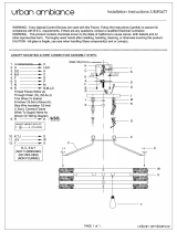
3 4 Installing a Space Heating System.
Zone control of VC unit
●Zone control of the VC unit is performed by a zero voltage or X-X
contact from a relay or zone control panel closing when unit
operation is required.
●You will find one brown wire looped to the upper Molex connector
of the main PC board. This wire can be cut and extended with
18 gauge thermostat wire and only connected to dry contacts from
your zone control panel end switch. See example wire diagrams on
the last four pages of this maual.
Pump Curves & Primary - Secondary Piping
●The boiler units include a pump assembly that is used to provide the
flow through the unit heat exchangers, and has a nominal flow of
heating water for external piping arrangements.
●This pump is not designed to be the system pump providing flow to
radiant loops or baseboard.
●Therefore VESTA insists on using a Promary-Secondary pumping
arrangement, the recommended method uses the traditional large
diameter Primary loop.
●The main circulation pump or the zone pumps will then provide
circulation into the zones or the heating system.
●The only exception to this Primary-Secondary rule is for Air Handling
units with a hot water coil where the Air handling unit is located less
than 10ft from the VC unit.
20 Installing the System Piping
/