
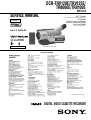
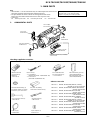
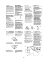
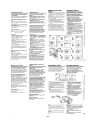
SERVICE MANUAL
DIGITAL VIDEO CASSETTE RECORDER
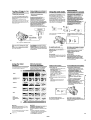
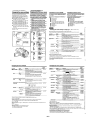
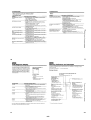
SPECIFICATIONS
RMT-814
DCR-TRV120E/TRV125E/
TR8000E/TR8100E
B700 MECHANISM
– Continued on next page –
Level 1
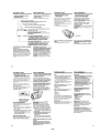
Photo: DCR-TRV120E
AEP Model
DCR-TRV120E/TRV125E/TR8000E/TR8100E
UK Model
East European Model
North European Model
Russian Model
DCR-TRV120E/TR8000E
Ver 1.0 2000. 02

– 2 –
1. Check the area of your repair for unsoldered or poorly-sol-
dered connections. Check the entire board surface for solder
splashes and bridges.
2. Check the interboard wiring to ensure that no wires are
“pinched” or contact high-wattage resistors.
3. Look for unauthorized replacement parts, particularly transis-
tors, that were installed during a previous repair. Point them
out to the customer and recommend their replacement.
SAFETY CHECK-OUT
After correcting the original service problem, perform the following
safety checks before releasing the set to the customer.
4. Look for parts which, though functioning, show obvious signs
of deterioration. Point them out to the customer and recom-
mend their replacement.
5. Check the B+ voltage to see it is at the values specified.
6. Flexible Circuit Board Repairing
• Keep the temperature of the soldering iron around 270 ˚C
during repairing.
• Do not touch the soldering iron on the same conductor of
the circuit board (within 3 times).
• Be careful not to apply force on the conductor when sol-
dering or unsoldering.
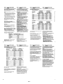
DCR-TR8000E
100×
×
×
Table for differences of function
DCR-TRV125E
125×
a
a
Model
Digital zoom
MONITOR IN
LCD
DCR-TRV120E
100×
a
a
DCR-TR8100E
125×
×
×
SAFETY-RELATED COMPONENT WARNING!!
COMPONENTS IDENTIFIED BY MARK 0 OR DOTTED
LINE WITH MARK 0 ON THE SCHEMATIC DIAGRAMS
AND IN THE PARTS LIST ARE CRITICAL TO SAFE
OPERATION. REPLACE THESE COMPONENTS WITH
SONY PARTS WHOSE PART NUMBERS APPEAR AS
SHOWN IN THIS MANUAL OR IN SUPPLEMENTS PUB-
LISHED BY SONY.

– 3 –
SERVICE NOTE
1. Power Supply During Repairs ....................................... 4
2. To Take Out a Cassette When Not Eject
(Force Eject) .................................................................. 4
3. Note for Repair .............................................................. 5
SELF-DIAGNOSIS FUNCTION
1. Self-diagnosis Function................................................. 6
2. Self-diagnosis Display................................................... 6
3. Service Mode Display ................................................... 6
3-1. Display Method.............................................................. 6
3-2. Switching of Backup No. ............................................... 6
3-3. End of Display ............................................................... 6
4. Self-diagnosis Code Table ............................................ 7
1. MAIN PARTS
1. Ornamental Parts .......................................................... 9
2. DISASSEMBLY
2-1. LCD Assembly (TRV Model) ......................................... 11
2-2. PD-117 Board (TRV Model) .......................................... 11
2-3. LCD Module (TRV Model) ............................................. 11
2-4. Front Panel Assembly ................................................... 11
2-5. Cassette Lid Assembly.................................................. 12
2-6. Cabinet (L) Assembly.................................................... 12
2-7. Cabinet (R) Assembly ................................................... 12
2-8. CF-69 Board (TRV Model) ............................................ 12
2-9. CF-71 Board (TR Model)............................................... 13
2-10. EVF Block...................................................................... 13
2-11. EVF Assembly............................................................... 13
2-12. VF-129 Board, CRT Assembly...................................... 13
2-13. Battery Panel Assembly ................................................ 14
2-14. Lens Block ..................................................................... 14
2-15. SE-104/113 Board......................................................... 14
2-16. Control Switch Block (FK-10000).................................. 14
2-17. FU-138/143 Board......................................................... 15
2-18. VC-235 Board................................................................ 15
3. REPAIR PARTS LIST
3-1. Exploded Views ............................................................. 16
3-1-1. Front Panel Section .................................................. 16
3-1-2. Cabinet (R) Section (TRV120E/TRV125E).............. 17
3-1-3. Cabinet (R) Section (TR8000E/TR8100E) .............. 18
3-1-4. EVF Block Section ................................................... 19
3-1-5. LCD Assembly Section (TRV120E/TRV125E) ........ 20
3-1-6. Cabinet (L) Section .................................................. 21
3-1-7. Lens Block Section................................................... 22
3-1-8. MAIN Board Section................................................. 23
4. GENERAL
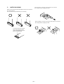
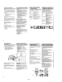
Checking Supplied Accessories............................................. 24
Quick Start Guide .................................................................... 24
Using This Manual ................................................................... 25
Step 1 Preparing the Power Supply ........................................ 25
Step 2 Inserting a Cassette..................................................... 27
Recording a Picture................................................................. 27
Checking the Recording
– END SEARCH/EDITSEARCH/Rec Review ......................... 30
Playing Back a Tape ................................................................ 30
Viewing the Recording on TV.................................................. 31
Recording a Still Image on a Tape
– Tape Photo Recording .......................................................... 32
Using the Wide Mode .............................................................. 33
Using the Fader Function ........................................................ 33
Using Special Effects
– Picture Effect ........................................................................ 34
Using Special Effects
– Digital Effect ......................................................................... 34
Using the PROGRAM AE Function......................................... 35
Adjusting the Exposure Manually............................................ 36
Focusing Manually................................................................... 36
Superimposing a Title.............................................................. 36
Making Your Own Titles ........................................................... 37
TABLE OF CONTENTS
Section Title Page Section Title Page
Inserting a Scene .................................................................... 37
Playing Back a Tape with Picture Effects ................................ 38
Playing Back a Tape with Digital Effects ................................. 38
Enlarging Recorded Images
– PB ZOOM ............................................................................. 38
Quickly Locating a Scene Using the Zero Set
Memory Function..................................................................... 38
Searching a Recording by Date
– Date Search.......................................................................... 39
Searching for a Photo
– Photo Search/Photo Scan.................................................... 39
Dubbing a Tape........................................................................ 40
Changing the Menu Settings................................................... 41
Resetting the Date and Time .................................................. 42
Digital8 System, Recording and Playback.............................. 43
Changing the Lithium Battery in Your Camcorder................... 43
Troubleshooting ....................................................................... 44
Self-diagnosis Display ............................................................. 45
Warning Indicators and Messages.......................................... 45
Using Your Camcorder Abroad................................................ 46
Maintenance Information and Precautions ............................. 46
Identifying the Parts and Controls........................................... 48

– 4 –
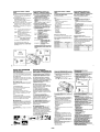
SERVICE NOTE
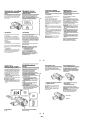
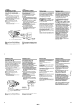
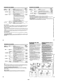
1. POWER SUPPLY DURING REPAIRS
In this unit, about 10 seconds after power is supplied (8.4 V) to the
battery terminal using the service power cord (J-6082-223-A), the
power is shut off so that the unit cannot operate.
This following two methods are available to prevent this. Take
note of which to use during repairs.
Method 1.
Connect the servicing remote commander RM-95 (J-6082-053-B)
to the LANC jack, and set the remote commander switch to the
“ADJ” side.
Method 2.
Press the battery switch of the battery terminal using adhesive tape,
etc.
Method 3.
Use the DC IN terminal. (Use the AC power adaptor.)
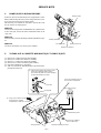
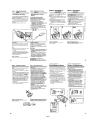
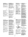
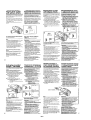
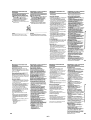
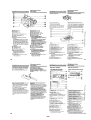
2. TO TAKE OUT A CASSETTE WHEN NOT EJECT (FORCE EJECT)
1Refer to 2-4 to remove the front panel assembly.
2Refer to 2-6 to remove the cabinet (L) assembly.
3Refer to 2-7 to remove the cabinet (R) assembly.
4Refer to 2-13 to remove the battery panel assembly.
5Disconnect CN4401 of VC-235 board.
6Add +5 V from the DC POWER SUPPLY and unload with a
pressing the cassette lid.
Battery switch
Battery terminal #
Battery terminal 3
Battery SIG terminal
DC IN terminal
7Pull the timing belt in the direction of the
arrow with a pincette while pressing
the cassette lid (take care not to damage)
to adjust the bending of a tape.
8Let go your hold the cassette
lid and rise the cassette
compartment to take out a cassette.
Pincette
Timing belt
Timing belt
Press the cassette lid to rise
the cassette compartment
[DC power supply]
(+5V)
Adjust the bending of a tape
Disconnect CN4401
of VC-235 board.
Loading motor

– 5 –
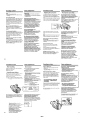
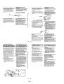
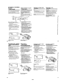
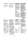
3. NOTE FOR REPAIR
Make sure that the flat cable and flexible board are not cracked of
bent at the terminal.
Do not insert the cable insufficiently nor crookedly.
When remove a connector, don’t pull at wire of connector.
Be in danger of the snapping of a wire.
Cut and remove the part of gilt
which comes off at the point.
(Take care that there are some
pieces of gilt left inside)
When installing a connector, don’t press down at wire of connector.
Be in danger of the snapping of a wire.

– 6 –
SELF-DIAGNOSIS FUNCTION
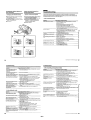
1. Self-diagnosis Function
When problems occur while the unit is operating, the self-diagno-
sis function starts working, and displays on the viewfinder or Dis-
play window what to do. This function consists of two display;
self-diagnosis display and service mode display.
Details of the self-diagnosis functions are provided in the Instruc-
tion manual.
Note: The “self-diagnosis display” data will be backed up by the coin-type lithium battery (CF-69/71 board BH001). When
this coin-type lithium battery is disconnected, the “self-diagnosis display” data will be lost by initialization.
2. Self-diagnosis Display
When problems occur while the unit is operating, the counter of
the viewfinder or Display window shows a 4-digit display consist-
ing of an alphabet and numbers, which blinks at 3.2 Hz. This 5-
character display indicates the “repaired by:”, “block” in which
the problem occurred, and “detailed code” of the problem.
3. Service Mode Display
The service mode display shows up to six self-diagnosis codes shown in the past.
3-1. Display Method
While pressing the “STOP” key, set the switch from OFF to “VTR or PLAYER”, and continue pressing the “STOP” key for 5 seconds
continuously. The service mode will be displayed, and the counter will show the backup No. and the 5-character self-diagnosis codes.
3-2. Switching of Backup No.
By rotating the control dial, past self-diagnosis codes will be shown in order. The backup No. in the [] indicates the order in which the
problem occurred. (If the number of problems which occurred is less than 6, only the number of problems which occurred will be shown.)
[1] : Occurred first time [4] : Occurred fourth time
[2] : Occurred second time [5] : Occurred fifth time
[3] : Occurred third time [6] : Occurred the last time
3-3. End of Display
Turning OFF the power supply will end the service mode display.
Order of previous errors
Backup No. Self-diagnosis Codes
C : 3 1 : 1 1
[3]
Lights up
Viewfinder
[3] C : 3 1 : 1 1
3 C : 3 1 : 11
Display window
1 1
3 1
C : 3 1 : 11
C
Repaired by:
Refer to page 10 and 11.
Self-diagnosis Code Table.
Indicates the appropriate
step to be taken.
E.g.
31 ....Reload the tape.
32 ....Turn on power again.
Block Detailed Code
Blinks at 3.2Hz
C : Corrected by customer
H : Corrected by dealer
E : Corrected by service
engineer
Viewfinder Display window
C : 3 1 : 1 1
Display window
Control dial

– 7 –
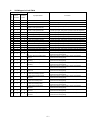
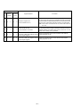
4. Self-diagnosis Code Table
C
C
C
C
C
C
C
C
C
C
C
C
C
C
C
C
C
C
C
C
C
C
C
C
C
C
C
C
C
Block
Function
21
22
23
31
31
31
31
31
31
31
31
31
31
31
31
31
32
32
32
32
32
32
32
32
32
32
32
32
32
Detailed
Code
00
00
00
10
11
20
21
22
23
30
31
40
41
42
43
44
10
11
20
21
22
23
30
31
40
41
42
43
44
Symptom/State
Condensation.
Video head is dirty.
Non-standard battery is used.
LOAD direction. Loading does not
complete within specified time
UNLOAD direction. Loading does not
complete within specified time
T reel side tape slacking when unloading
.
S reel
side tape slacking when unloading
.
T reel fault.
S reel fault.
FG fault when starting capstan.
FG fault during normal capstan operations.
FG fault when starting drum.
PG fault when starting drum.
FG fault during normal drum operations.
PG fault during normal drum operations.
Phase fault during normal drum operations.
LOAD direction loading motor time-
out.
UNLOAD direction loading motor
time-out.
T reel side tape slacking when
unloading.
S reel side tape slacking when
unloading.
T reel fault.
S reel fault.
FG fault when starting capstan.
FG fault during normal capstan
operations.
FG fault when starting drum.
PG fault when starting drum.
FG fault during normal drum
operations.
PG fault during normal drum
operations.
Phase fault during normal drum
operations.
Self-diagnosis Code
Repaired by:
Correction
Remove the cassette, and insert it again after one hour.
Clean with the optional cleaning cassette.
Use the InfoLITHIUM battery.
Load the tape again, and perform operations from the beginning.
Load the tape again, and perform operations from the beginning.
Load the tape again, and perform operations from the beginning.
Load the tape again, and perform operations from the beginning.
Load the tape again, and perform operations from the beginning.
Load the tape again, and perform operations from the beginning.
Load the tape again, and perform operations from the beginning.
Load the tape again, and perform operations from the beginning.
Load the tape again, and perform operations from the beginning.
Load the tape again, and perform operations from the beginning.
Load the tape again, and perform operations from the beginning.
Load the tape again, and perform operations from the beginning.
Load the tape again, and perform operations from the beginning.
Remove the battery or power cable, connect, and perform
operations from the beginning.
Remove the battery or power cable, connect, and perform
operations from the beginning.
Remove the battery or power cable, connect, and perform
operations from the beginning.
Remove the battery or power cable, connect, and perform
operations from the beginning.
Remove the battery or power cable, connect, and perform
operations from the beginning.
Remove the battery or power cable, connect, and perform
operations from the beginning.
Remove the battery or power cable, connect, and perform
operations from the beginning.
Remove the battery or power cable, connect, and perform
operations from the beginning.
Remove the battery or power cable, connect, and perform
operations from the beginning.
Remove the battery or power cable, connect, and perform
operations from the beginning.
Remove the battery or power cable, connect, and perform
operations from the beginning.
Remove the battery or power cable, connect, and perform
operations from the beginning.
Remove the battery or power cable, connect, and perform
operations from the beginning.

– 8 –
E
E
E
E
Block
Function
61
61
62
62
Detailed
Code
00
10
00
01
Symptom/State
Difficult to adjust focus
(Cannot initialize focus.)
Zoom operations fault
(Cannot initialize zoom lens.)
Handshake correction function does not
work well. (With pitch angular velocity
sensor output stopped.)
Handshake correction function does not
work well. (With yaw angular velocity
sensor output stopped.)
Self-diagnosis Code
Repaired by:
Correction
Inspect the lens block focus reset sensor (Pin 9 of CN1551 of
VC-235 board) when focusing is performed when the control dial
is rotated in the focus manual mode and the focus motor drive circuit
(IC1553 of VC-235 board) when the focusing is not performed.
Note: Use the remote commander RM-95 only for the model without the
focus dial.
Inspect the lens block zoom reset sensor (Pin 0 of CN1551 of
VC-235 board) when zooming is performed when the zoom lens is
operated and the zoom motor drive circuit (IC1553 of VC-235
board) when zooming is not performed.
Inspect pitch angular velocity sensor (SE201 of SE-104/113
board) peripheral circuits.
Inspect yaw angular velocity sensor (SE202 of SE-104/113
board) peripheral circuits.

– 9 –
1. MAIN PARTS
Note:
• Items marked “*” are not stocked since they are seldom required for routine service.
Some delay should be anticipated when ordering these items.
• The parts numbers of such as a cabinet are also appeared in this section.
Refer to the parts number mentioned below the name of parts to order.
• Abbreviation
EE : East European model
1. ORNAMENTAL PARTS
The components identified by mark 0 or dotted
line with mark 0 are critical for safety.
Replace only with part number specified.
DCR-TRV120E/TRV125E/TR8000E/TR8100E
NE : North European model RU : Russian model
Jack cover
3-058-723-01
Lens cap assembly
X-3949-376-1
Jack lid
3-987-656-01
CPC lid (BT)
3-975-752-01
Battery case lid
3-742-854-01
Remote Commander (RMT-814)
1-475-141-61
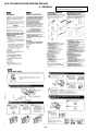
Checking supplied accessories.
Check that the following accessories are supplied with your camcorder.
Wireless Remote
Commander (1)
RMT-814
1-475-141-61
Mains lead (1)
01-769-608-11
(EXCEPT TRV120E: UK/TR8000E: UK)
01-783-374-11
(TRV120E: UK/TR8000E: UK)
NP-F330 battery pack (1)
(TRV120E/TR8000E)
NP-F550 battery pack (1)
(TRV125E/TR8100E)
R6 (Size AA) battery
for Remote Commander (2)
AC-L10A/L10B/L10C
AC power adaptor (1)
01-475-599-11
A/V connecting cable (1)
1-765-080-11
21-pin adaptor (1)
1-573-291-11
Lens cap (1)
X-3949-376-1
Shoulder strap (1)
3-987-015-01
CR2025 lithium battery (1)
The lithium battery is already
installed in your camcorder.
Other accessories
3-058-872-11 MANUAL, INSTRUCTION (ENGLISH, RUSSIAN)
(TRV120E: UK, EE, NE, RU/TRV125E)
3-058-872-21 MANUAL, INSTRUCTION (SPANISH, PORTUGUESE)
(TRV120E: AEP/TRV125E)
3-058-872-31 MANUAL, INSTRUCTION (DUTCH, ITALIAN)
(TRV120E: AEP/TRV125E)
3-058-872-41 MANUAL, INSTRUCTION (GERMAN, FRENCH)
(TRV120E:AEP/TRV125E)
3-058-872-51 MANUAL, INSTRUCTION (POLISH, SWEDISH)
(TRV120E: EE, NE,RU)
3-058-874-11 MANUAL, INSTRUCTION (ENGLISH, RUSSIAN)
(TR8000E: UK, EE, NE, RU/TR8100E)
3-058-874-21 MANUAL, INSTRUCTION (SPANISH, PORTUGUESE)
(TR8000E: AEP/TR8100E)
3-058-874-31 MANUAL, INSTRUCTION (DUTCH, ITALIAN)
(TR8000E: AEP/TR8100E)
3-058-874-41 MANUAL, INSTRUCTION (GERMAN, FRENCH)
(TR8000E: AEP/TR8100E)
3-058-874-51 MANUAL, INSTRUCTION (POLISH, SWEDISH)
(TR8000E: EE, NE, RU)

– 10 –
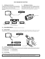
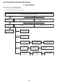
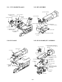
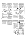
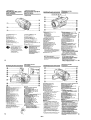
2. DISASSEMBLY
DCR-TRV120E/TRV125E/TR8000E/TR8100E
Note: TRV model : DCR-TRV120E/TRV125E
TR model : DCR-TR8000E/TR8100E
•This set can be disassembled in the order shown below.
DCR-TRV120E/TRV125E/TR8000E/TR8100E
2-4. FRONT PANEL ASSEMBLY
(page 11)
2-7. CABINET (R) ASSEMBLY
(page 12)
2-5. CASSETTE LID ASSEMBLY
(page 12)
2-6. CABINET (L) ASSEMBLY
(page 12)
2-1. LCD ASSEMBLY
(page 11)
2-2. PD-117 BOARD
(page 11)
2-3. LCD MODULE
(page 11)
2-17. FU-138/143
BOARD
(page 15)
2-10. EVF BLOCK
(page 13)
2-8. CF-69 BOARD
(page 12)
2-9. CF-71 BOARD
(page 13)
2-11. EVF ASSEMBLY
(page 13)
2-12. VF-129 BOARD,
CRT ASSEMBLY
(page 13)
2-18. VC-235 BOARD
(page 15)
2-13. BATTERY PANEL
ASSEMBLY
(page 14)
TRV model
TRV model
TR model
2-14. LENS BLOCK
(page 14)
2-16. CONTROL SWITCH BLOCK
(FK-10000)
(page 14)
2-17. SE-104/113
BOARD
(page 15)

– 11 –
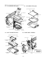
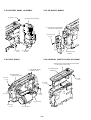
Note: Follow the disassembly procedure in the numerical order given.
2-1. LCD ASSEMBLY (TRV model) 2-3. LCD MODULE (TRV model)
2-2. PD-117 BOARD (TRV model) 2-4. FRONT PANEL ASSEMBLY
3Two screws 5Claw
0LCD assembly
1Open the
LCD panel.
4Claw
7Three connectors
(CN5701, 5702,
5704)
2Two screws
(P2 × 4)
6P cabinet (C)
9Two screws
8Flexible board
(CN5703)
1Flexible board
(CN5501)
2Flexible board
(CN5604)
3Two claws
4PD-117 board
6Claw
5Flexible board
(CN5705)
8Claw
9Indication (LCD) block assembly
7Claw
4LCD module
1Claw
2Cold cathode fluorescent tube
3Claw
1Screw (2 × 4)
2Jack cover
3Two screws
(2 × 4)
6Front panel assembly
7Flexible board
(CN5804)
Cushion
(SE)
4Two screws
(2 × 4)
Note: Remove it while
taking care as
the flexible board
is connected.
5Two claws

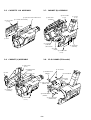
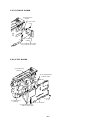
– 12 –
2-5. CASSETTE LID ASSEMBLY 2-7. CABINET (R) ASSEMBLY
2-6. CABINET (L) ASSEMBLY 2-8. CF-69 BOARD (TRV model)
1Two screws
(2 × 4)
5Cassette lid assembly
4Claw
2Open the control switch block.
3Claw
1Two screws
(2 × 4)
6Flexible board
(CN253)
4Claw
5Cabinet (L)
assembly
3Two screws
(2 × 4)
2Screw (2 × 4)
5Flat cable
(CN1105)
2Two screws
(2 × 4) 1Screw
(2 × 4)
4Cabinet (R)
assembly
3Three screws
(2 × 4)
7Screw
(tripod)
6Connector
(CN1109)
(TRV model)
3Flexible board
(CN006)
1Two connectors
(CN004, 005)
2Flexible board
(CN002)
7Two connectors
(CN003, 008)
4Six screws
6CF-69 board
5Rotary
switch

– 13 –
2-9. CF-71 BOARD (TR model) 2-11. EVF ASSEMBLY
2-10. EVF BLOCK 2-12. VF-129 BOARD, CRT ASSEMBLY
4Two screws
6CF-71 board
5Rotary
switch
8Two screws
2Lithium battery
retainer
1Two screws
3Three screws
9Indication (LCD)
block assembly
7Flexible board
(CN006)
3Screw
5EVF block
2screw
1Flat cable
CN005 ... TR model
CN007 ... TRV model
4Claw
6Two screws
1Harness guide
2Two screws
(2 × 4)
3VF base assembly
4Flat cable
5Rotate the
VF hinge assembly.
7EVF assembly
1F lock screw
3Turn the finder assembly in
the direction of arrow A and
pull it out.
A
4Two screws
6EVF cabinet (upper)
assembly
7CRT assembly
8Screw
9EVF tally
2Release knob.
5Claw
qg CRT
socket qd Anode cable
qs Cover
0Remove the VF-129
board in the direction
of arrow B.
Bqf Connector
(CN902)
qa Flat cable

– 14 –
2-13. BATTERY PANEL ASSEMBLY 2-15. SE-104/113 BOARD
2-14. LENS BLOCK 2-16. CONTROL SWITCH BLOCK (FK-10000)
3Screw (2 × 4)
4Battery panel assembly
2Screw
(2 × 4) 1Connector
(CN252)
3Screw
(2 × 3)
8Flexible board
(external connector)
1Two flexible baords
(CN1501, 1551)
4Screw
(2 × 3)
7Lens block
6Lens frame
2Screw
(2 × 3)
5Claw
2Four screws
(2 × 3)
1Flexible board
(CN202)
3SE-104 board (TRV model)
SE-113 board (TR model)
3Screw
(2 × 3)
2Screw
(2 × 3)
1Flexible board
(CN1107)
4Remove the control switch block (FK-10000)
in the direction of the arrow.

– 15 –
2-17. FU-138/143 BOARD
2-18. VC-235 BOARD
1Two screws
(2 × 3)
2Connector
(CN254)
3FU-138 board (TRV model)
FU-143 board (TR model)
4Flexible board
(CN235)
1Flexible board
(CN1107)
4Two flexible boards
(CN4403, 4404)
5Screw
(2 × 3)
6VC-235 board
3Three flexible boards
(CN3101, 4401, 4402)
2Flexible board
(CN1103)

NOTE:
• -XX and -X mean standardized parts, so they may
have some difference from the original one.
• Color Indication of Appearance Parts
Example:
KNOB, BALANCE (WHITE) . . . (RED)
↑↑
Parts Color Cabinet's Color
• Items marked “*” are not stocked since they are
seldom required for routine service. Some delay
should be anticipated when ordering these items.
• The mechanical parts with no reference number in
the exploded views are not supplied.
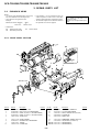
– 16 –
3. REPAIR PARTS LIST
3-1. EXPLODED VIEWS
DCR-TRV120E/TRV125E/TR8000E/TR8100E
The components identified by mark
0 or dotted line with mark 0 are
critical for safety.
Replace only with part number speci-
fied.
Ref. No. Part No. Description RemarkRef. No. Part No. Description Remark
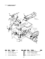
3-1-1. FRONT PANEL SECTION
• Abbreviation
EE : East European model
NE : North European model
1 X-3949-376-1 CAP (N) ASSY, LENS
2 X-3950-220-1 GRILLE (2.5) ASSY, MICROPHONE
3 X-3950-218-1 PANEL (2.5) ASSY, F (TRV120E/TR8000E)
3 X-3950-254-1 PANEL (2.5) ASSY, F (TRV125E/TR8100E)
4 3-968-729-01 SCREW (2X4)
5 3-987-717-01 SCREW (TRIPOD)
6 X-3950-221-1 RETAINER ASSY, MICROPHONE
7 3-948-339-61 TAPPING
*8 3-059-031-01 CUSHION (MI)
13
414
15
11
79
10
7
84
4
44
5
3
2
1
MIC5802, 5803
4
12
4
6
7
9 not supplied MI-37 BOARD, COMPLETE
10 1-676-818-31 FP-156 FLEXIBLE BOARD
11 1-790-334-11 CABLE, FLEXIBLE FLAT (FFC-257S)
*12 3-059-032-01 CUSHION (SE)
13 3-058-723-01 COVER, JACK
14 1-475-141-61 COMMANDER, REMOTE (RMT-814)
15 3-742-854-01 LID, BATTERY (for RMT-814)
MIC5802 1-542-312-11 MICROPHONE (L)
MIC5803 1-542-312-11 MICROPHONE (R)
RU : Russian model

– 17 –
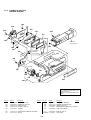
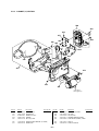
3-1-2. CABINET (R) SECTION
(TRV120E/TRV125E)
Ref. No. Part No. Description Remark
Ref. No. Part No. Description Remark
51 3-058-670-11 COVER (R) (101), HINGE
52 3-948-339-61 TAPPING
53 3-941-343-21 TAPE (A)
54 X-3950-235-1 CABINET (R) (101) ASSY
55 3-959-978-02 CUSHION, PANEL
56 3-058-698-01 KNOB (100), MF
57 3-058-697-01 RETAINER (100), MF
*58 3-059-650-01 BLIND (B) (101), VF
59 1-418-801-11 SWITCH BLOCK, CONTROL (MF-10000)
*60 3-058-659-01 RETAINER (101), SPEAKER
*61 3-058-658-01 SPACER (101), SPEAKER
62 not supplied CF-69 BOARD, COMPLETE
S008 1-771-848-11 SWITCH, PUSH (PANEL OPEN/CLOSE)
SP003 1-529-590-11 SPEAKER (2.0cm)
52
52 62
53
52
60
52
S008
59
52
not supplied
56
54
52
53
51
52
55
LCD assembly
(See page 20)
58
52
SP003
61
52
EVF block
(See page 19)
57

– 18 –
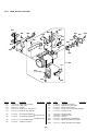
Ref. No. Part No. Description Remark
Ref. No. Part No. Description Remark
3-1-3. CABINET (R) SECTION
(TR8000E/TR8100E)
109
105
105
105
105
108
107
105
106
105
not supplied
104
102
103
101
113
not supplied
(LCD904)
not supplied
105
105
EVF block
(See page 19)
111
110
LED904
112
101 3-058-700-01 WINDOW (100), LCD
102 X-3950-238-1 CABINET (R) (100) ASSY
103 3-058-698-01 KNOB (100), MF
104 3-058-697-01 RETAINER (100), MF
105 3-948-339-61 TAPPING
106 1-418-801-11 SWITCH BLOCK, CONTROL (MF-10000)
107 3-941-343-21 TAPE (A)
108 not supplied CF-71 BOARD, COMPLETE
109 3-053-717-11 RETAINER, LITHIUM BATTERY
110 3-058-699-01 HOLDER (100), LCD
111 not supplied INDICATION (LCD) BLOCK ASSY (SERVICE)
*112 3-058-900-01 SHEET (100), MUFFLE
*113 3-059-649-01 BLIND (B) (100), VF
0LED904 not supplied LIGHT, BACK
The components identified by mark
0 or dotted line with mark 0 are
critical for safety.
Replace only with part number speci-
fied.

– 19 –
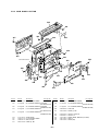
Ref. No. Part No. Description Remark
Ref. No. Part No. Description Remark
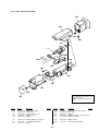
3-1-4. EVF BLOCK SECTION
164
162
155
163
161
160
159
157
156
154
155
153
151
152
158
V901
*151 3-058-641-01 GUIDE (100), HARNESS
152 3-968-729-01 SCREW (2X4)
153 X-3950-234-1 BASE (B) (100) ASSY, VF
154 X-3950-230-1 HINGE ASSY, VF
155 3-948-339-81 TAPPING
156 3-058-644-01 CABINET (LOWER) (B) (100), EVF
157 not supplied VF-129 BOARD, COMPLETE
158 3-941-343-21 TAPE (A)
159 1-792-454-11 CABLE, FLEXIBLE FLAT (FFC-289)
160 3-053-681-01 TALLY, EVF
161 3-948-339-61 TAPPING
162 X-3950-233-1 CABINET (UPPER) (B) (100) ASSY, EVF
163 3-975-898-01 SCREW (T), F LOCK
164 X-3949-329-1 FINDER (S) ASSY
0V901 not supplied CRT ASSY (M01KXX90WB)
The components identified by mark
0 or dotted line with mark 0 are
critical for safety.
Replace only with part number speci-
fied.

– 20 –
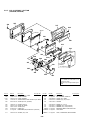
3-1-5. LCD ASSEMBLY SECTION
(TRV120E/TRV125E)
Ref. No. Part No. Description Ref. page No.Ref. No. Part No. Description Ref. page No.
216 215
214
217
208
211
218
210
213
212
206
209
203
201
202
204
205
207
208
not supplied
(LCD902)
not supplied
LED901
ND901
LCD901
201 3-058-671-01 COVER (C) (101), HINGE
202 3-948-339-31 SCREW, TAPPING
*203 3-058-672-01 CLAMP, HARNESS
204 1-418-802-11 SWITCH BLOCK, PANEL REVERSE (PR-10000)
205 4-981-286-01 SCREW (M1.7X2) (IB LOCK)
206 1-960-225-11 HARNESS (DP-83)
207 3-058-673-01 COVER (M), HINGE
208 3-968-729-01 SCREW (2X4)
209 X-3950-237-1 HINGE ASSY
210 not supplied INDICATION (LCD) BLOCK ASSY (SERVICE)
211 3-058-667-01 HOLDER (101), LCD
212 3-713-786-21 SCREW (M2X3)
213 not supplied PD-117 BOARD, COMPLETE
214 3-058-666-01 FRAME (101), PANEL
215 X-3950-236-1 CABINET (M) (101) ASSY, P
216 3-948-339-81 TAPPING
217 3-058-665-01 CABINET (C) (101), P
218 3-058-668-11 WINDOW (101), LCD (TRV120E)
218 3-058-668-21 WINDOW (101), LCD (TRV125E)
LCD901 not supplied INDICATOR MODULE LIQUID CRYSTAL
0LED901 not supplied LIGHT, BACK
0ND901 not supplied TUBE, FLUORESCENT, COLD CATHODE
The components identified by mark
0 or dotted line with mark 0 are
critical for safety.
Replace only with part number speci-
fied.
Page is loading ...
Page is loading ...
Page is loading ...
Page is loading ...
Page is loading ...
Page is loading ...
Page is loading ...
Page is loading ...
Page is loading ...
Page is loading ...
Page is loading ...
Page is loading ...
Page is loading ...
Page is loading ...
Page is loading ...
Page is loading ...
Page is loading ...
Page is loading ...
Page is loading ...
Page is loading ...
Page is loading ...
Page is loading ...
Page is loading ...
Page is loading ...
Page is loading ...
Page is loading ...
Page is loading ...
Page is loading ...
Page is loading ...
Page is loading ...
Page is loading ...
-
 1
1
-
 2
2
-
 3
3
-
 4
4
-
 5
5
-
 6
6
-
 7
7
-
 8
8
-
 9
9
-
 10
10
-
 11
11
-
 12
12
-
 13
13
-
 14
14
-
 15
15
-
 16
16
-
 17
17
-
 18
18
-
 19
19
-
 20
20
-
 21
21
-
 22
22
-
 23
23
-
 24
24
-
 25
25
-
 26
26
-
 27
27
-
 28
28
-
 29
29
-
 30
30
-
 31
31
-
 32
32
-
 33
33
-
 34
34
-
 35
35
-
 36
36
-
 37
37
-
 38
38
-
 39
39
-
 40
40
-
 41
41
-
 42
42
-
 43
43
-
 44
44
-
 45
45
-
 46
46
-
 47
47
-
 48
48
-
 49
49
-
 50
50
-
 51
51


Ask a question and I''ll find the answer in the document
Finding information in a document is now easier with AI
Related papers
-
Sony DCR-TRV120E User manual
-
Sony SPK-TRC User manual
-
-
Sony DCR-PC101 User manual
-
-
-
-
-
-
