
(English)
Dealer's Manual
ROAD MTB Trekking
City Touring/
Comfort Bike URBAN SPORT E-BIKE
Dual Pivot Caliper Brake /
Dual Control Lever (Di2)
DURA-ACE
ST-R9250
BR-R9200
BR-R9210
ULTEGRA
ST-R8150
BR-R8100
BR-R8110
Non-Series
BR-RS811-R
SW-RS801-S
SW-RS801-T
DM-RACBR10-00

2
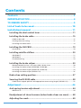
Contents
Contents ...................................................................................2
IMPORTANT NOTICE ..................................................................4
TO ENSURE SAFETY ...................................................................5
List of tools to be used ..........................................................10
Installation/removal ..............................................................11
Installing the dual control lever ..........................................................11
Installing the brake cable ....................................................................15
• Cable to be used ..................................................................................................................... 16
• Cutting the outer casing ........................................................................................................ 16
• Installing the brake cable ...................................................................................................... 18
Installing the SM-CB90 .........................................................................19
• Installation .............................................................................................................................. 20
Installing satellite shifters ...................................................................20
• SW-RS801-T ............................................................................................................................. 21
• SW-RS801-S ............................................................................................................................. 25
• Troubleshooting ..................................................................................................................... 29
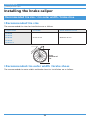
Installing the brake caliper ..................................................................30
• Recommended tire size / rim outer width / brake shoe ....................................................... 30
• Installing the brake caliper (BR-R9200 / BR-R8100) .............................................................. 32
• Installing the brake caliper (BR-R9210 / BR-R8110) .............................................................. 33
• Installing the brake caliper (BR-RS811-R) .............................................................................. 36
Brake shoe setting position .................................................................37
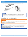
Securing the BC-9000 cable .................................................................38
• Cable outer stopper position and appropriate outer casing length (BR-RS811-R)............. 42
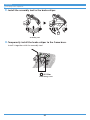
Adjustment .............................................................................44
Arch spring tension adjustment ..........................................................44
• BR-RS811-R .............................................................................................................................. 44
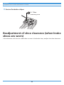
Readjustment of shoe clearance (when brake shoes are worn) ......48
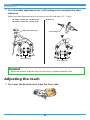
Adjusting the reach ..............................................................................49

3
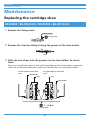
Maintenance ...........................................................................51
Replacing the cartridge shoe ...............................................................51
• BR-R9200 / BR-R9210-RS / BR-R8100 / BR-R8110-RS .............................................................. 51
• BR-R9210-F / BR-R8110-F / BR-RS811-R .................................................................................. 52
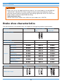
Brake shoe characteristics ...................................................................53
Replacing the bracket cover ................................................................54

4
IMPORTANT NOTICE
IMPORTANT NOTICE
• This dealer's manual is intended primarily for use by professional bicycle mechanics.
Users who are not professionally trained for bicycle assembly should not attempt to
install the components themselves using the dealer's manuals.
If any part of the information on the manual is unclear to you, do not proceed with the
installation. Instead, contact your place of purchase or a distributor for assistance.
•Make sure to read all manuals included with the product.
•Do not disassemble or modify the product other than as stated in the information
contained in this dealer's manual.
•All manuals and technical documents are accessible online at https://si.shimano.com.
•For consumers who do not have easy access to the internet, please contact a SHIMANO
distributor or any of the SHIMANO offices to obtain a hardcopy of the User's Manual.
•Please observe the appropriate rules and regulations of the country, state or region in
which you conduct your business as a dealer.
For safety, be sure to read this dealer's manual thoroughly before use, and
follow it for correct use.
The following instructions must be observed at all times in order to prevent personal injury
and physical damage to equipment and surroundings.
The instructions are classified according to the degree of danger or damage which may occur
if the product is used incorrectly.
DANGER Failure to follow the instructions will result in death or serious
injury.
WARNING Failure to follow the instructions could result in death or
serious injury.
CAUTION Failure to follow the instructions could cause personal injury or
physical damage to equipment and surroundings.

5
TO ENSURE SAFETY
TO ENSURE SAFETY
WARNING
• Be sure to follow the instructions provided in the manuals when installing the product.
Only use SHIMANO genuine parts. If a component or replacement part is incorrectly
assembled or adjusted, it can lead to component failure and cause the rider to lose
control and crash.
•Wear approved eye protection while performing maintenance tasks such as
replacing components.
Be sure to also inform users of the following:
•Because each bicycle may handle slightly differently depending on the model, be sure to
learn the proper braking technique (including brake lever pressure and bicycle control
characteristics) and operation of your bicycle. Improper use of your bicycle's brake system
may result in a loss of control or a fall, which could lead to severe injury.
•Do not apply the front brake too strongly. If you do so, the front wheel may lock and the
bicycle may fall forward, and serious injury may result.
•Always make sure that the front and rear brakes are working correctly before riding the
bicycle.
•Because the required braking distance will be longer during wet weather, reduce your
speed and apply the brakes early and gently. You may fall or collide and be seriously
injured.
•A wet road surface may cause tires to lose traction; therefore, to avoid this, reduce your
speed and apply the brakes early and gently. If the tires lose traction, you may fall and be
seriously injured.
•Do not allow any oil or grease to get onto the brake shoes. Riding the bicycle with oil or
grease on the brake shoes may prevent the brakes from operating and result in serious
injury due to a fall or collision.
•Do not use the brake cable if it has any rust, fraying, or cracks. Otherwise, the brakes may
not work correctly.
Dual control lever
•Do not throw or subject this product to strong shocks. If this is not observed, bursting,
overheating or problems with operation may occur.
•When operating the shift switch, be careful not to allow your fingers to be caught in the
derailleur. The motor in the derailleur is powerful enough to be operated without
stopping until the shifting position is reached, and may cause serious injury if your
fingers interfere with the shifting motion.

6
TO ENSURE SAFETY
For installation to the bicycle and maintenance
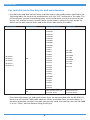
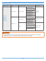
•Use the brake and dual control levers or brake lever in the combinations specified in the
following table. Do not use the combinations with the “NO” indication in the table. This
will excessively increase the braking force, which could cause you to lose control of the
bicycle, fall, and be seriously injured. (Refer to the dealer's manual for each model for
details on the dual control levers and brake levers indicated in the table.)
Caliper brake Combinations Dual control lever Brake lever
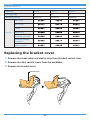
BR-R9200
BR-R9210
BR-R8100
BR-R8110
BR-RS811-R
OK
ST-R9250
ST-R9100
ST-R9150
ST-R9160
ST-R8150
ST-R8050
ST-R8000
ST-R7000
ST-9070
ST-9071
ST-9001
ST-9000
ST-6870
ST-6871
ST-6800
ST-6770
ST-6700
ST-5800
ST-5700
ST-4700
ST-4600
ST-R3000
ST-3500
ST-2400
ST-R460
ST-R353
ST-R350
BL-4700
BL-4600
BL-R3000
BL-3500
BL-R2000
BL-R780
BL-2400
BL-TT79
NO Dual control levers not
included above
Brake levers not
included above
•The cable adjustment nut and quick release lever are not provided with the BR-RS811-R;
be sure to use the SM-CB90 (cable adjuster). When the brake shoes are worn down, it
becomes impossible to adjust the shoe clearance by hand. Also confirm that the SM-CB90
is in the “Close” position before riding the bicycle.

7
TO ENSURE SAFETY
•Securely tighten the caliper brake fixing nuts to the specified tightening torque. If the
nuts become loose and the brakes fall off, they may get caught up in the bicycle and the
bicycle may fall over. In particular, if this happens with the front wheel, you may be
thrown forward and seriously injured.
•Use lock nuts with nylon inserts (self-locking nuts) for nut-type brakes.
•For sunken nut-type brakes, use sunken nuts of the appropriate length which can be
threaded onto the fixing screw for at least six full turns. When re-assembling, apply a
threadlocker to the nut threads.
•Brakes designed for use as rear brakes should not be used as front brakes. Also, brakes
designed for use as front brakes should not be used as rear brakes.
•Make sure to use the dedicated brake shoe for the shoe holder of the BR-R9210-F /
R8110-F / RS811-R. The conventional brake shoes have different fixing positions
preventing the fixing screw from being tightened, which will cause the brake shoe to
come off and disable braking.
Dedicated brake shoes:
R55C4 / R55C4 (for carbon rim) / R55C4-A (for carbon rim) / R55CT4
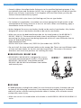
•Do not install the shoe and shoe holder on the wrong side. There are two different types
of shoe and shoe holder for the left and right respectively. Take note of the correct
directions and screw hole positions for inserting the shoes.
BR-R9210-RS / BR-R8110-RS
•BR-R9210-RS / BR-R8110-RS is designed for use as a
rear brake and should not be used as a front brake.
BR-R9210-F / BR-R8110-F (front brake) and BR-
R9210-RS / BR-R8110-RS use different shoe holders
and internal parts.
BR-R9210-F /
BR-R8110-F
BR-R9210-RS /
BR-R8110-RS
Shoe holder
BC-9000
BC-9000 (polymer coating brake cable) has low frictional resistance; therefore, be sure
to observe the following instructions. If not observed, the holding force of the brake
cable will not be sufficient causing the brake cable to slacken, a loss of brake control
and possibly severe injury.
•Make sure to use it in combination with a brake in the BR-R9210 / BR-R8110 / BR-RS811-R
series.

8
TO ENSURE SAFETY
•Use the designated Cable Grease (Y04180000) for BC-9000.
•When the inner cable is passed through the outer casing, be sure to wipe the inner cable
fixing section with a cloth before fixing the inner cable. Grease may adhere to the inner
cable fixing section and prevent sufficient holding force.
NOTICE
Be sure to also inform users of the following:
•In the case of carbon levers, wash them with a soft cloth using a neutral detergent.
Otherwise, the material may be damaged and lose strength.
•Avoid leaving the carbon levers in areas of high temperature. Also keep them well away
from fire.
•When combined with a ceramic rim, SHIMANO road brake shoes wear down more
quickly.
•If the brake shoes have worn down until the grooves are no longer visible, consult your
place of purchase or a distributor.
•Different brake shoes have their own characteristics. Ask the place of purchase or a
distributor for details when purchasing the brake shoes.
•Be sure to keep rotating the crank arm during gear shifting operations.
•Be careful not to get water into the E-TUBE ports and the satellite shifter connection
port.
•The components are designed to be fully waterproofed to withstand wet weather riding
conditions; however, do not deliberately place them into water.
•Do not clean the bicycle with a high-pressure washer. If water gets into any of the
components, operating problems or rusting may result.
•Contact the place of purchase for updates of the component software. The most up-to-
date information is available on the SHIMANO website.
•Be sure to attach dummy plugs to any unused E-TUBE ports and the satellite shifter
connection port. If water gets into any of the components, operating problems or rusting
may result.
•The electric wire has small waterproof connectors, so do not repeatedly connect and
disconnect it too often. Doing so may impair the waterproofing.
•Products are not guaranteed against natural wear and deterioration from normal use
and aging.

9
TO ENSURE SAFETY
•For maximum performance we highly recommend SHIMANO lubricants and maintenance
products.
For installation to the bicycle and maintenance
•Use an outer casing / electric wire which still has some length to spare even when the
handlebars are turned all the way to either side. Furthermore, check that the dual control
levers do not touch the bicycle frame when the handlebars are turned all the way.
•Use the parts indicated in the part breakdown of the dual control levers when you
replace the clamp band, clamp screw, or clamp nut.
•Even with the recommended tightening torque, there is a possibility that the carbon
handlebars may become damaged and insufficiently tightened. Confirm the appropriate
torque value with the bicycle manufacturer or the handlebar manufacturer.
Dual control lever
•Dummy plugs are installed at the time of shipment from the factory. Do not remove
them except when necessary.
•When routing the electric wires, take care to ensure that they do not interfere with the
brake levers.
Satellite shifter
•When connecting electric wires, make sure that foreign matter does not get inside the
plug or satellite shifter connection port. A connection with foreign matter present may
result in a malfunction.
•If the plug is exposed during storage, transportation, or maintenance work, and there is
a possibility of foreign matter getting inside, protect the plug with masking tape or a
similar material.
•If you do not feel a click when connecting an electric wire, check that there is no foreign
matter inside the plug or satellite shifter connection port. If foreign matter is present, use
a blower to remove it. If the problem persists, replace the satellite shifter with a new
one.
The actual product may differ from the illustration because this manual is
intended mainly to explain the procedures for using the product.

10
List of tools to be used
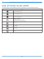
List of tools to be used
The following tools are needed for installation, adjustment, and maintenance purposes.
Tool
2 mm hexagon wrench
4 mm hexagon wrench
5 mm hexagon wrench
Slotted screwdriver
Blade width at tip: 4.0 - 5.0 mm
Blade thickness at tip: 0.5 - 0.6 mm
TL-CT12
TL-EW300
Utility knife
Cutters

11
Installation/removal
Installing the dual control lever
Installation/removal
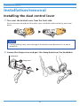
Installing the dual control lever
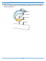
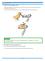
1. Turn over the bracket cover from the front side.
Gently turn over the ends of the bracket cover with both hands and slowly push them
down.
NOTICE
•Forcibly pulling it may cause damage to the bracket cover because of its material
properties.
2. Loosen the clamp screw and pass the clamp band over the handlebar.
Clamp screw
Clamp band

12
Installation/removal
Installing the dual control lever
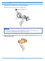
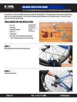
3. Temporarily install the lever to the handlebar.
Temporarily install the lever so that it cannot move.
Clamp screw (Temporary)
NOTICE
•Use the parts indicated in the part breakdown of the dual control levers when
you replace the clamp band, clamp screw, or clamp nut.
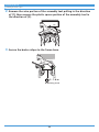
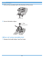
4. Return the turned bracket cover to its original position and turn it over
from the back side.

13
Installation/removal
Installing the dual control lever
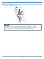
5. Lift up the port junction.
Port junction
Bracket cover
NOTICE
•When removing / inserting dummy plugs or electric wires, be sure the port
junction is firmly supported by hand or by the bracket body. Otherwise you may
cause damage to the inner connecting wires of the dual control lever.

14
Installation/removal
Installing the dual control lever
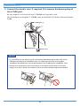
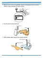
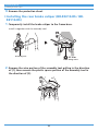
6. Connect the electric wire. If required, first remove the dummy plug of
the E-TUBE port.
Be sure to push it in firmly with the TL-EW300 until you feel a click.
For instructions on using the TL-EW300, refer to the ROAD Di2 Dealer's Manual General
Guide.
E-TUBE port ×2
Dummy plug
Electric wire
NOTICE
•It is possible for the electric wires to become disconnected accidentally while
riding or winding the handlebar tape. By allowing sufficient wire length,
accidental disconnection can be prevented after winding the handlebar tape.
•Ensure that the electric wire to connect to the dual control levers has extra
length to make it easier to remove and insert when performing maintenance.

15
Installation/removal
Installing the brake cable
TECH TIPS
•PC linkage devices can be connected to the E-TUBE port when performing
maintenance. However, leave the dummy plug attached to the unused E-TUBE
port when a PC linkage device is not in use.
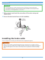
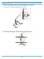
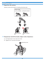
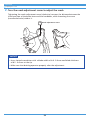
7. Wire, connect, and check the connection of the outer casing and
electric wire.
8. Secure the dual control levers to the handlebar.
6 - 8 N·m
Clamp screw
Installing the brake cable
Outer casing comes internally pre-lubricated with an appropriate grease.
WARNING
•When an inner cable is passed through the outer casing, be sure to wipe the fixing
section of the inner cable which will be secured by the clamp screw before securing the
cable. Residual grease in the area of the clamp screw may prevent sufficient holding
force.

16
Installation/removal
Installing the brake cable
NOTICE
•Be careful not to let the BC-9000 inner cable come into contact with the shifting lever
or the metallic part (adjustment section) of the caliper brake. If the coating of the
cable gets abraded during installation, it may develop a fuzzy appearance, although
this will not affect performance.
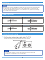
Cable to be used
BC-9000 inner cable BC-9000 outer casing
Ø1.6 mm Ø5 mm
BC-1051 inner cable SLR outer casing
Ø1.6 mm Ø5 mm
Cutting the outer casing
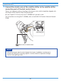
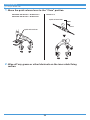
1. Cut the outer casing using a cable cutter (TL-CT12).
Cut the outer casing so that the coil does not tip over inward.
NOTICE
•Cut the outer casing so it still has some length to spare even when the
handlebars are turned all the way to either side.

17
Installation/removal
Installing the brake cable
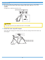
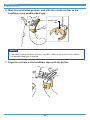
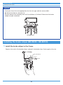
2. Spread out the tip of the liner using a thin tool such as a TL-CT12
needle.
Arrange the cut end into a perfect circle.
TL-CT12 needle
CAUTION
•Be careful not to hurt your hands with the TL-CT12 needle.
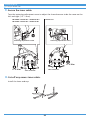
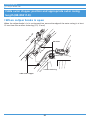
3. Install the outer cap with tongue.
Insert the outer casing until it closely contacts with the seating surface of the outer cap
with tongue.
BR-R9200 / R9210-RS
BR-R8100 / R8110-RS
BR-RS811-R

18
Installation/removal
Installing the brake cable
NOTICE
•When inserting the outer casing, take care to ensure that the tip of the outer
cap with tongue is not damaged.
•When using the BC-1051 inner cable, use a regular outer cap rather than an
outer cap with tongue.
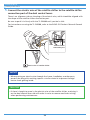
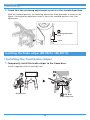
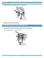
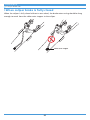
Installing the brake cable
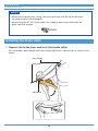
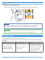
1. Depress the brake lever and insert the brake cable.
Pass the brake cable through the outer casing and install it to the lever as shown in the
figure.
Outer casing
Inner end
Cable hook

19
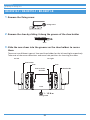
Installation/removal
Installing the SM-CB90
NOTICE
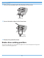
•Make sure that the inner end is firmly fit into the cable hook.
Cable hook
Inner end
2. Temporarily secure the outer casing to the handlebar (by using tape or
a similar material).
Tape
Outer casing
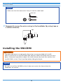
Installing the SM-CB90
WARNING
•The cable adjustment nut and quick release lever are not provided with the BR-
RS811-R; be sure to use the SM-CB90 (cable adjuster). When the brake shoes are worn
down, it becomes impossible to adjust the shoe clearance by hand. Also confirm that
the SM-CB90 is in the “Close” position before riding the bicycle.
NOTICE
•Be sure to install the SM-CB90 so that it does not contact the frame when the
handlebars are turned.

20
Installation/removal
Installing satellite shifters
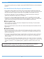
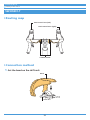
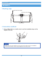
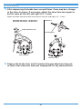
Installation
1. Install the SM-CB90.
(1) Pass the inner cable through the SM-CB90 and install it to the outer casing on the
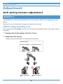
brake lever side.
(2) Move the quick release lever to the “Open” position.
(3) Install the outer casing on the brake caliper side to the SM-CB90.
(4) Move the quick release lever to the “Close” position.
Inner cable
Self-locking nut
(1)
(3)
Open
Close
Outer casing on
the brake caliper
side
Outer casing on
the brake lever side
Quick release lever
(2)
(4)
NOTICE
•Ensure the orientation of the SM-CB90 is the same as is illustrated in the figure.
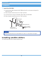
Installing satellite shifters
This section describes how to add a satellite shifter.
Page is loading ...
Page is loading ...
Page is loading ...
Page is loading ...
Page is loading ...
Page is loading ...
Page is loading ...
Page is loading ...
Page is loading ...
Page is loading ...
Page is loading ...
Page is loading ...
Page is loading ...
Page is loading ...
Page is loading ...
Page is loading ...
Page is loading ...
Page is loading ...
Page is loading ...
Page is loading ...
Page is loading ...
Page is loading ...
Page is loading ...
Page is loading ...
Page is loading ...
Page is loading ...
Page is loading ...
Page is loading ...
Page is loading ...
Page is loading ...
Page is loading ...
Page is loading ...
Page is loading ...
Page is loading ...
Page is loading ...
Page is loading ...
-
 1
1
-
 2
2
-
 3
3
-
 4
4
-
 5
5
-
 6
6
-
 7
7
-
 8
8
-
 9
9
-
 10
10
-
 11
11
-
 12
12
-
 13
13
-
 14
14
-
 15
15
-
 16
16
-
 17
17
-
 18
18
-
 19
19
-
 20
20
-
 21
21
-
 22
22
-
 23
23
-
 24
24
-
 25
25
-
 26
26
-
 27
27
-
 28
28
-
 29
29
-
 30
30
-
 31
31
-
 32
32
-
 33
33
-
 34
34
-
 35
35
-
 36
36
-
 37
37
-
 38
38
-
 39
39
-
 40
40
-
 41
41
-
 42
42
-
 43
43
-
 44
44
-
 45
45
-
 46
46
-
 47
47
-
 48
48
-
 49
49
-
 50
50
-
 51
51
-
 52
52
-
 53
53
-
 54
54
-
 55
55
-
 56
56


Shimano ST-R8150 Dealer's Manual
- Type
- Dealer's Manual
- This manual is also suitable for
Ask a question and I''ll find the answer in the document
Finding information in a document is now easier with AI
Related papers
-
Shimano BR-R450 Owner's manual
-
-
Shimano BR-R7010 Dealer's Manual
-
Shimano BR-5710 Dealer's Manual
-
Shimano SM-EWC2 Dealer's Manual
-
Shimano BR-R2000 Dealer's Manual
-
Shimano SM-RT800 Dealer's Manual
-
Shimano BR-4600 Dealer's Manual
-
-
Other documents
-
 KOGEL Shimano Dura Ace R9100 Oversized Derailleur Cage Installation guide
-
Netgear R8000 User manual
-
Diamondback SHEPPARD CYCLES Owner's manual
-
Infinity Mountain Bicycle Owner's manual
-
 Pacific Cycle Bicycle Owner's manual
-
 Stitch KM2002-1-JV Operating instructions
-
 Pacific Cycle Mountain Bicycles; BMX Bicycles User manual
-
Currier Tech Ezip Owner's manual
-
 Merida Bike User manual
-
Centurion ROAD BIKE ISO 4210-2 User manual


