
CUB CADET LLC, P.O. BOX 361131 CLEVELAND, OHIO 44136-0019
Printed In USA
OperatOr’s Manual
Safe Operation Practices • Set-Up • Operation • Maintenance • Service • Troubleshooting • Warranty
WARNING
READ AND FOLLOW ALL SAFETY RULES AND INSTRUCTIONS IN THIS MANUAL
BEFORE ATTEMPTING TO OPERATE THIS MACHINE.
FAILURE TO COMPLY WITH THESE INSTRUCTIONS MAY RESULT IN PERSONAL INJURY.
Form No. 769-09301
(September 5, 2013)
Tank L

To The Owner 1
2
Safe Operation Practices ........................................ 3
Assembly & Set-Up .................................................11
Controls & Features ................................................17
Operation ............................................................... 20
Maintenance & Adjustment ................................ 27
Service .................................................................... 34
Troubleshooting .................................................... 39
Replacement Parts ................................................ 40
Warranties ............................................................. 42
Table of Contents
Product Registration and Customer Support
Please register your product on our website, www.cubcadet.com.
If you have difficulty assembling this product or have any questions regarding the controls, operation, or maintenance of
this machine, you can seek help from the experts. Choose from the options below:
◊ Visit us on the web at www.cubcadet.com
See How-to Maintenance and Parts Installation Videos at www.cubcadet.com/tutorials
◊ Locate your nearest Cub Cadet Dealer at (877) 282-8684
◊ Write to Cub Cadet LLC • P.O. Box 361131 • Cleveland, OH • 44136-0019
Thank You
Record Product Information
Before setting up and operating your new equipment, please
locate the model plate on the equipment and record the
information in the provided area to the right. The model plate is
located under the seat on the seat frame. This information will be
necessary, should you seek technical support via our web site or
with your local Cub Cadet dealer.
Model NuMber
Serial NuMber
Thank you for purchasing a Cub Cadet Zero-Turn Tractor. It was
carefully engineered to provide excellent performance when
properly operated and maintained.
Please read this entire manual prior to operating the equipment.
It instructs you how to safely and easily set up, operate and
maintain your machine. Please be sure that you, and any other
persons who will operate the machine, carefully follow the
recommended safety practices at all times. Failure to do so could
result in personal injury or property damage.
All information in this manual is relative to the most recent
product information available at the time of printing. Review
this manual frequently to familiarize yourself with the machine,
its features and operation. Please be aware that this Operator’s
Manual may cover a range of product specifications for various
models. Characteristics and features discussed and/or illustrated
in this manual may not be applicable to all models. We reserve
the right to change product specifications, designs and
equipment without notice and without incurring obligation.
If applicable, the power testing information used to establish
the power rating of the engine equipped on this machine can be
found at www.opei.org or the engine manufacturer’s web site.
If you have any problems or questions concerning the machine,
phone your local Cub Cadet dealer or contact us directly. Cub
Cadet’s Customer Support telephone numbers, website address
and mailing address can be found on this page. We want to
ensure your complete satisfaction at all times.
Throughout this manual, all references to right and left side of the
machine are observed from the operating position
The engine manufacturer is responsible for all engine-related
issues with regards to performance, power-rating, specifications,
warranty and service. Please refer to the engine manufacturer’s
Owner’s/Operator’s Manual, packed separately with your
machine, for more information.

Important Safe Operation Practices 2
3
WARNING! This symbol points out important safety instructions which, if not followed,
could endanger the personal safety and/or property of yourself and others. Read and follow
all instructions in this manual before attempting to operate this machine. Failure to comply
with these instructions may result in personal injury.
When you see this symbol, HEED ITS WARNING!
WARNING! This machine is equipped with an internal combustion engine and should not be
used on or near any unimproved forest-covered, brush-covered or grass-covered land unless
the engine’s exhaust system is equipped with a spark arrestor meeting applicable local or
state laws (if any). If a spark arrestor is used, it should be maintained in effective working
order by the operator. In the state of California the above is required by law (Section 4442 of
the California Public Resources Code). Other states may have similar laws. Federal laws apply
on federal lands. A spark arrestor for the muffler is available through your nearest engine
authorized service dealer or contact the service department, P.O. Box 361131, Cleveland, Ohio
44136- 0019.
This spark ignition system complies with Canadian ICES-002.
DANGER! The engine manufacturer has supplied an engine owner’s manual for information
regarding US Environmental Protection Agency (EPA) and California Air resources Board (CARB)
regulations relating to emission control systems, maintenance, and warranty. Making any
unauthorized alterations or modifications to the engine, fuel, or venting systems may violate EPA
and/or CARB regulations. Further information may be obtained from the engine manufacturer.
DANGER! This machine was built to be operated according to the safe operation practices in
this manual. As with any type of power equipment, carelessness or error on the part of the
operator can result in serious injury. This machine is capable of amputating hands and feet
and throwing objects. Failure to observe the following safety instructions could result in
serious injury or death.
CALIFORNIA PROPOSITION 65
WARNING! Engine Exhaust, some of its constituents, and certain vehicle components
contain or emit chemicals known to the State of California to cause cancer and birth
defects or other reproductive harm.
WARNING! Battery posts, terminals, and related accessories contain lead and lead
compounds, chemicals known to the State of California to cause cancer and reproductive
harm. Wash hands after handling.

4Section 2 — important Safe operation practiceS
Training
1. Read the Operator’s manual and other training material. If
the operator(s) or mechanic(s) cannot read English it is the
owner’s responsibility to explain this material to them.
2. Become familiar with the safe operation of the machine,
operator controls, and safety signs.
3. All operators and mechanics should be trained to operate
or service the equipment. The owner is responsible for
training them.
4. Never let children under the age of 16 or untrained people
operate or service the equipment. Local regulations may
further restrict the age of the operator.
5. The owner/operator can prevent and is responsible for
accidents or injuries occurring to them, other people or
property.
General Operation
1. Read, understand, and follow all instructions on the
machine and in the manual(s) before attempting to
assemble and operate. Keep this manual in a safe place
for future and regular reference by each operator and for
ordering replacement parts.
2. Be familiar with all controls and their proper operation.
Know how to stop the machine and disengage the controls
quickly.
3. Do not allow anyone to operate or maintain this machine
who has not read the manual. Never permit children under
the age of 16 to operate this machine.
4. Do not remove any shields, guards, labels or safety devices.
If a shield, guard, label or safety device is damaged or
does not function, repair or replace it before operating the
machine.
5. To help avoid blade contact or a thrown object injury,
keep bystanders, helpers, children and pets at least 75 feet
from the machine while it is in operation. Stop machine if
anyone enters the area.
6. Thoroughly inspect the area where the equipment is to be
used. Remove all stones, sticks, wire, bones, toys, and other
foreign objects that could be picked up and thrown by the
blade(s). Thrown objects can cause serious personal injury.
7. Evaluate the terrain to determine what accessories and
attachments are needed to properly and safely perform
the job. Only use accessories and attachments approved
by the machine manufacturer.
8. Plan your mowing pattern to avoid discharge of material
toward roads, sidewalks, bystanders and the like. Also,
avoid discharging material against a wall or obstruction
which may cause discharged material to ricochet back
toward the operator.
9. Always wear appropriate clothing and personal protective
equipment (e.g. safety glasses, long pants, gloves, hearing
protection , safety shoes, hard hat) when operating or
maintaining this machine. Long hair, loose fitting clothing
or jewelry may get entangled in moving parts. Follow all
federal, state and local guidelines regarding the use of
personal protective equipment.
10. Be aware of the mower and attachment discharge direction
and do not point it at anyone. Do not operate the mower
without the discharge cover or entire grass catcher in its
proper place.
11. Do not put hands or feet near rotating parts or under the
cutting deck. Contact with the blade(s) can amputate
hands and feet.
12. A missing or damaged discharge cover can cause blade
contact or thrown object injuries.
13. Stop the blade(s) when crossing gravel drives, walks, or
roads and while not cutting grass.
14. Watch for traffic when operating near or crossing
roadways. This machine is not intended for use on any
public roadway.
15. Do not operate the machine while under the influence of
alcohol or drugs.
16. Mow only in daylight or good artificial light.
17. Never carry passengers.
18. Back up slowly. Always look down and behind before and
while backing to avoid a back-over accident.
19. Slow down before turning. Operate the machine smoothly.
Avoid erratic operation and excessive speed. Be aware of
your direction of travel to avoid accidents.
20. Disengage blade(s), set parking brake, stop engine and wait
until the blade(s) come to a complete stop before removing
grass catcher, emptying grass, unclogging chute, removing
any grass or debris, or making any adjustments.
21. Never leave a running machine unattended. Always stop
on level ground, turn off blade(s), place drive speed control
levers in neutral, set parking brake, stop engine and remove
key before leaving the operator position.
22. Use extra care when loading or unloading the machine
on a trailer or truck. The machine should not be driven on
unstable, unsecured or inadequate ramps because the
machine could tip over causing serious personal injury.
23. Check overhead clearances carefully before driving under
low hanging tree branches, wires, door openings etc.,
where the operator and/or ROPS may be struck which
could result in serious injury and/or machine tip over.
24. Muffler and engine become hot and can cause a burn. Do
not touch.
25. Disengage the blades, set the parking brake to the ‘ON’
position and make sure the speed control lever are in the
neutral position before attempting to start the engine.
Only start the engine from the operator’s position.
26. Do not attempt to mow unusually tall, dry grass (e.g.,
pasture) or piles of dry leaves. Dry grass or leaves may
contact the engine exhaust and/or build up on the mower
deck presenting a potential fire hazard.
27. Do not stop or park the machine over dry leaves, grass,
debris or other combustible material.

5Section 2 — important Safe operation practiceS
28. Never attempt to operate the machine without the
mowing deck attached; the machine could tip over.
29. Keep the machine and especially the engine exhaust
system and hydraulic components clean and free of grease,
grass and leaves to reduce the potential for overheating
and fire.
30. Allow the machine to cool at least 5 minutes before storing.
31. Use only accessories and attachments approved for this
machine by the machine manufacturer. Read, understand
and follow all instructions provided with the approved
accessory or attachment.
32. Data indicates that operators, age 60 years and above, are
involved in a large percentage of riding mower-related
injuries. Operators should evaluate their ability to operate
this machine safely enough to protect themselves and
others from serious injury.
33. Do not operate or start machine if there is fuel or oil leaks;
repair immediately.
34. When looking for oil leaks, never run your hand over
hydraulic hoses, lines or fittings. Never tighten or adjust
hydraulic hoses, lines or fittings while the system is under
pressure. If high-pressure oil penetrates the skin seek
immediate medical attention or gangrene and permanent
damage may result. Do not check for hydraulic leaks with
your hands, use paper or cardboard instead. Wear gloves
and safety glasses when checking for leaks.
35. Do not operate machines that have been damaged or have
not been properly maintained. If the machine has been
damaged, then have it repaired.
36. When operating this machine in the forward direction, do
not allow the speed control levers to return to the neutral
position on their own. Always operate them smoothly and
avoid any sudden movements of the levers when starting
or stopping.
37. If situations occur which are not covered in this manual use
care and good judgement. Contact your customer service
representative for assistance.
Slope Operation
Slopes are a major factor related to loss of control and tip-over
accidents that can result in severe injury or death. All slopes
require extra caution. If you cannot back up the slope or if you
feel uneasy on it, do not mow it or drive on the slope.
For your safety, use the slope gauge included as part of this
manual to measure slopes before operating this machine on
a sloped or hilly area. If the slope is greater than 20 degrees as
shown on the slope gauge, do not operate this machine on that
area or serious injury could result.
Do:
1. Mow across slopes, not up and down. Exercise extreme
caution when changing direction on slopes.
2. Watch for holes, ruts, bumps, rocks, or other hidden
objects. Uneven terrain could overturn the machine. Tall
grass can hide obstacles.
3. Use slow speed. Choose a low enough speed so that you
will not have to stop while on the slope. Avoid starting
or stopping on a slope. If the tires are unable to maintain
traction, disengage the blades and proceed slowly and
carefully straight down the slope.
4. Keep all movements on the slopes slow and gradual. Do
not make sudden changes in speed or direction. Rapid
acceleration could cause the front of the machine to lift
and rapidly flip over backwards, which could cause serious
injury or death.
5. Follow the manufacturer’s recommendations for wheel
weights or counterweights to improve stability.
6. Use extra care with grass catchers or other attachments.
These can change the stability of the machine.
Do Not:
1. Do not turn on slopes unless necessary; then turn slowly
uphill and use extra care while turning.
2. Do not mow near drop-offs, ditches or embankments. The
machine could suddenly turn over if a wheel is over the
edge of a cliff, ditch, or if an edge caves in.
3. Do not operate on slopes or near the edge of water such as
a lake, pond, river or stream where the machine could slip,
tip or roll-over into the water.
4. Do not try to stabilize the machine by putting your foot on
the ground.
5. Do not use a grass catcher on slopes steeper than 15
degrees.
6. Do not mow on wet grass. Reduced traction could cause
sliding and/or loss of control.
7. Do not tow heavy pull behind attachments (e.g. loaded
dump cart, lawn roller, etc.) on slopes greater than 5
degrees. When going downhill, the extra weight tends
to push the machine and may cause loss of traction and
loss of control (e.g. machine may speed up, braking and
steering ability are reduced, attachment may jack-knife and
cause machine to overturn).
Children
1. Tragic accidents can occur if the operator is not alert to the
presence of children. Children are often attracted to the
machine and the mowing activity. They do not understand
the dangers. Never assume that children will remain where
you last saw them.
a. Keep children out of the mowing area and in
watchful care of a responsible adult other than the
operator.
b. Be alert and turn machine off if a child enters the
area.
c. Always look behind and down for small children. Use
slow speed.
d. Never carry children, even with the blade(s) shut off.
They may fall off and be seriously injured or interfere
with safe machine operation.
e. Use extreme care when approaching blind corners,
doorways, shrubs, trees or other objects that may
block your vision of a child who may run into the
path of the machine.
f. To avoid back-over accidents, always disengage
blades before traveling in reverse.
g. Keep children away from hot or running engines.
They can suffer burns from a hot muffler.
h. Remove key when machine is unattended to
prevent unauthorized operation.

6Section 2 — important Safe operation practiceS
2. Never allow children under 16 years of age to operate this
machine. Children 16 and over should read and understand the
instructions and safe operation practices in this manual and on
the machine and should be trained and supervised by an adult.
Towing
1. Do not tow heavy tow-behind attachments (e.g. loaded
dump cart, lawn roller, etc.) on slopes greater than 5
degrees.
2. Tow only with a machine that has a hitch designed for
towing. Do not attach towed equipment except at the
hitch point.
3. Follow the manufacturer’s recommendation for weight
limits for towed equipment and towing on slopes.
4. Never allow children or others in or on towed equipment.
5. On slopes, the weight of the towed equipment may cause
loss of traction and loss of control.
6. Travel slowly and allow extra distance to stop.
7. Make wide turns to avoid jack knifing
Transporting Machines
1. This machine is not intended for use on public roads.
Machines operated on public roads must comply with state
& local ordinances, SAE J137, and ANSI/ASABE S279 (lighting
and marking requirements).
2. Use care when loading or unloading machines onto trailers
and trucks.
3. If ramps are used, they must be full width, stable, have an
adequate capacity rating and be secured to the trailer or
truck. Ramp angle should not exceed 15 degrees and trailer
or truck should be parked on level terrain.
4. Machines must be secured onto trailers and trucks with
straps, chains, cables, ropes, or other means deemed
adequate for that purpose. The front and rear of the
machines must be secured to the trailer or truck in both the
lateral and vertical directions.
Operator Protective System (OPS)
1. This machine is equipped with an Operator Protective
System (OPS), which includes:
a. A Roll Over Protective Structure (ROPS) of the fixed
or folding configuration.
b. Seat belt assembly with retractable function.
2. ROPS are structures designed to provide a crush-resistant
space for the operator when properly seat-belted within
the designated seating area of the machine in the event of
a machine tip-over or roll-over. Folding ROPS shall be used
in their fully upright and locked configurations except in
those circumstances whereby they need to be momentarily
folded-down to avoid contact with items such as tree
limbs, clothes lines, guy wires, utility poles, buildings, etc.
At other times and conditions, ROPS shall be in their fully
upright and locked configurations.
DANGER: Damaged ROPS must be replaced
prior to operator use!
3. Seat belts shall be used and shall be properly fastened
about the operator’s waist at all times, except when the
ROPS are:
a. Not properly installed and/or not properly secured
onto the machine.
b. Damaged in such manner that their structural
integrity has been compromised.
c. Not in their fully upright and locked position.
4. Seat belts are attached to the movable portion of the seat
when suspension seats are utilized, and therefore the seat-
mounting base must be secured to its pivot means and the
pivot means latched to the frame of the machine. Seat belts
are attached to the seat or the frame of the machine when
non-suspension (standard) seats are provided, however, if
a suspension kit is added to a seat, the seat belt must be
attached to the movable portion of the seat or suspension
mechanism, the seat-mounting base must be secured to its
pivot means, and the pivot means be latched to the frame
of the machine.
DANGER: If ROPS are folded down or missing,
seat belts shall not be fastened. Worn or damaged
seat belt assemblies must be replaced prior to
operator use.
5. A brush guard or canopy may deflect tree limbs, clothes
lines, and other obstacles that otherwise could come in
contact with the ROPS. Contact of ROPS and/or canopies
by items such as tree limbs, clothes lines, guy wires, and
buildings, could create hazardous conditions whereby
the machine could experience a tip-over or roll-over. A
canopy may provide protection for the operator from some
environmental exposure (sunlight, rain, etc.).
6. The ROPS and seat belt are integral parts of this machine
and should not be tampered with, modified in any manner,
or removed.
7. Inspect the ROPS and seat belt assemblies on a regular
basis for damage and improper operation. Replace all
components that are damaged or are not functioning
properly with authorized replacement parts.
8. The ROPS extends above and behind the operator position,
and therefore the operator must be aware of potential
contact of the ROPS with items such as trees, buildings,
doorways, clothes lines, utility wires, etc., that could cause
the machine to tip-over or rollover. Use caution in (or avoid)
areas where the ROPS could come in contact with any
structures, trees, etc.
9. Inspect the ROPS and seat belt assemblies on a regular
basis for damage and improper operation. Replace all
components that are damaged or are not functioning
properly with authorized replacement parts.
10. Failure to use the seat belt properly could result in serious
injury or death if an accidental overturn occurs. In order
for the ROPS to be effective, the seat belt must be securely
fastened around the operator at all times when the
operator is on the machine. Contact with the ROPS during
an overturn could cause serious injury or death.
11. The ROPS will not prevent machine from tip-overs or roll-overs.
12. Do not assume ROPS will protect you in a tip-over or roll-
over. Injuries may still occur.

7Section 2 — important Safe operation practiceS
Hydraulic Devices and Systems
Hydraulic fluid escaping under pressure may have sufficient
force to penetrate skin and cause serious injury. If foreign fluid is
injected into the skin or eyes, see immediate medical attention or
gangrene and permanent damage may result.
WARNING: Keep body and hands away from
pinholes or nozzles that could inject hydraulic fluid
under high pressure. Use paper or cardboard, not
your hands, to search for leaks! Wear gloves and
safety glasses.
Safely relieve all pressure in the system before performing any
work on the system, and make sure that:
• The ignition switch is OFF
• The key is removed
• The engine spark plug wire(s) removed
• All connections to the negative terminal of the battery are
removed
• The park brake is set
• All by-pass valves, if so equipped, are open
• Hydraulic controls are actuated to release pressure on
pumps, cylinders, etc. If “float” positions are available, they
should be used.
After the above operations are completed, it should be safe to
begin disconnecting the lines or components. It is still a good
idea to cover the connection with a cloth shield and then gently
loosen connections.
WARNING: Make sure all hydraulic fluid
connections are tight and all hydraulic hoses and
lines are in good condition before applying pressure
to the system.
Service
Safe Handling of fuel
1. To avoid personal injury or property damage use extreme
care in handling fuel. Fuel is extremely flammable and the
vapors are explosive. Serious personal injury can occur
when fuel is spilled on yourself or your clothes which can
ignite. Wash your skin and change your closes immediately.
a. Use only approved containers.
b. Never fill containers inside a vehicle or a truck or
trailer bed with a carpeted or plastic liner. Always
place containers on the ground away from your
vehicle before fueling.
c. When practical, remove machines from the truck or
trailer and refuel it on the ground. If this is not possible,
then refuel equipment on a trailer with a portable
container rather than from a fuel dispenser nozzle.
d. Keep nozzle in contact with the rim of the fuel tank
or container opening at all times until fueling is
complete. Do not use a nozzle lock-open device.
e. Extinguish all cigarettes, cigars, pipes and other
sources of ignition.
f. Never fuel machine indoors or near ignition sources.
g. Never remove fuel cap or add fuel while the engine
is hot or running. Allow engine to cool at least two
minutes before refueling.
h. Never over fill fuel tank. Fill tank to no more than ½ inch
below bottom of filler neck to allow space for expansion.
i. If necessary, use a funnel to avoid spillage.
j. Replace fuel cap and tighten securely.
k. If fuel is spilled, wipe off the engine and equipment.
Wait 5 minutes before starting the engine.
l. To reduce fire hazards, keep machine free of grass,
leaves, or other debris build-up. Clean up oil and fuel
spillage and remove any fuel soaked debris.
m. Never store the machine or fuel container inside
where there is an open flame, spark or pilot light
as on a water heater, space heater, furnace, clothes
dryer or other gas appliance.
General Service
1. Never run an engine indoors or in a poorly ventilated area.
Engine exhaust contains carbon monoxide, an odorless,
and deadly gas.
2. Before cleaning, repairing, or inspecting, make certain the
blade(s) and all moving parts have stopped. Disconnect the
spark plug wires and remove the key from the ignition to
prevent unintended starting.
3. Periodically check to make sure the blades come to
complete stop within approximately (7) seven seconds
after operating the blade disengagement control. If the
blades do not stop within this time frame, your machine
should be serviced.
4. Never tamper with the safety interlock system or other
safety devices.
5. Regularly check the safety interlock system for proper
function, as described later in this manual. If the safety
interlock system does not function properly, have your
machine serviced.
6. Check brake operation frequently as it is subjected to wear
during normal operation. Adjust and service as required.
7. Check the blade(s) and engine mounting bolts at frequent
intervals for proper tightness. Also, visually inspect blade(s)
for damage (e.g., excessive wear, bent, cracked). Replace the
blade(s) with the original equipment manufacturer’s (O.E.M.)
blade(s) only, listed in this manual. “Use of parts which do
not meet the original equipment specifications may lead to
improper performance and compromise safety!”
8. Mower blades are sharp. Wrap the blade or wear gloves,
and use extra caution when servicing them.
9. Keep all nuts, bolts, and screws tight to be sure the
equipment is in safe working condition.
10. After striking a foreign object (or if abnormal vibration
occurs), stop the blades and engine and thoroughly inspect
the machine for any damage. Make necessary repairs
before resuming operation.
11. Never attempt to make adjustments or repairs to the
machine while the engine is running.

8Section 2 — important Safe operation practiceS
WARNING! Your Responsibility—Restrict the use of this power machine to persons who read, understand and
follow the warnings and instructions in this manual and on the machine.
SAVE THESE INSTRUCTIONS!
12. Grass catcher components and the discharge cover are
subject to wear and damage which could expose moving
parts or allow objects to be thrown. For safety protection,
frequently check components and replace immediately
with original equipment manufacturer’s (O.E.M.) parts only,
listed in this manual. “Use of parts which do not meet the
original equipment specifications may lead to improper
performance and compromise safety!”
13. Do not change the engine governor settings or over-speed
the engine. The governor controls the maximum safe
operating speed of the engine.
14. Maintain or replace safety and instruction labels, as necessary.
15. Observe proper disposal laws and regulations for gas, oil,
etc. to protect the environment.
Do not modify engine
To avoid serious injury or death, do not modify engine in any
way. Tampering with the governor setting can lead to a runaway
engine and cause it to operate at unsafe speeds. Never tamper
with factory setting of engine governor.
Notice Regarding Emissions
This machine is equipped with an engine that is certified to
federal EPA emission standards for non-road engines and
equipment, and where applicable to California Air Resources
Board (CARB) emission standards. The engine owner’s manual is
supplied by the engine manufacturer, and provides additional
information relating to the emission system, warranty,
maintenance of the engine in accordance with EPA and/or
CARB regulations. Making any unauthorized alterations or
modifications to the engine, fuel, or venting systems may violate
EPA and CARB regulations.
When required, models are equipped with low permeation fuel
lines and fuel tanks for evaporative emission control. California
models may also include a carbon canister. Please contact
Customer Support for information regarding the evaporative
emission control configuration for your model.
This machine is designed to run on regular, unleaded gasoline,
87 octane or higher. Never use gasoline containing methanol or
gasoline containing more than 10% ethanol (i.e., E15 or E85 fuels)
because the fuel system may be damaged.

9Section 2 — important Safe operation practiceS
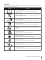
Safety Symbols
This page depicts and describes safety symbols that may appear on this product. Read, understand, and follow all instructions on the
machine before attempting to assemble and operate.
Symbol Description
READ THE OPERATOR’S MANUAL(S)
Read, understand, and follow all instructions in the manual(s) before attempting to
assemble and operate
WARNING— ROTATING BLADES
Do not put hands or feet near rotating parts or under the cutting deck. Contact with the
blade(s) can amputate hands and feet.
WARNING—THROWN OBJECTS
This machine may pick up and throw objects which can cause serious personal injury.
WARNING—THROWN OBJECTS
This machine may pick up and throw objects which can cause serious personal injury.
BYSTANDERS
Keep bystanders, helpers, children and pets at least 75 feet from the machine while it is in
operation.
MAX
WARNING— SLOPE OPERATION
Do not operate this machine on a slope greater than 15 degrees.
DANGER — ROTATING BLADES
To reduce the risk of injury, keep hands and feet away. Do not operate unless discharge cover
or grass catcher is in its proper place. If damaged, replace immediately.
DANGER — ROTATING BLADES
Never carry passengers. Never carry children, even with the blades off.
DANGER — ROTATING BLADES
Always look behind and down for small children. Use slow speed.
DANGER — ROTATING BLADES
To avoid back-over accidents, keep children away from the machine while it is in operation.

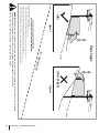
10 Section 2 — Safe operation practiceS
(OK) (TOO STEEP)
USE THIS SLOPE GAUGE TO DETERMINE
IF A SLOPE IS TOO STEEP FOR SAFE OPERATION!
To check the slope, proceed as follows:
1. Remove this page and fold along the dashed line.
2. Locate a vertical object on or behind the slope (e.g. a pole, building, fence, tree, etc.)
3. Align either side of the slope gauge with the object (See Figure 1 and Figure 2 ).
4. Adjust gauge up or down until the left corner touches the slope (See Figure 1 and Figure 2).
5. If there is a gap below the gauge, the slope is too steep for safe operation (See Figure 2 above).
15° dashed line
Slope Gauge
Figure 2Figure 1
15° Slope
15° Slope
WARNING! Slopes are a major factor related to tip-over and roll-over accidents which can result in severe injury or death.
Do not operate machine on slopes in excess of 15 degrees. All slopes require extra caution.
Always mow across the face of slopes, never up and down slopes.

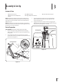
Assembly & Set-Up 3
11
Contents of Crate
• One Zero-Turn Tractor • One ROPS Assembly • One Deck Wash Hose Coupler
• One Zero-Turn Tractor Operator’s
Manual
• One Engine Operator’s Manual
NOTE: This Operator’s Manual covers several models. Tractor
features may vary by model. Not all features in this manual are
applicable to all tractor models and the tractor depicted may
differ from yours.
NOTE: All references in this manual to the left or right side and
front or back of the tractor are from the operating position only.
Exceptions, if any, will be specified.
Tractor Preparation
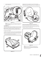
TOOLS NEEDED: Safety glasses, leather gloves, wire cutters.
1. Remove the upper crating material from the shipping
pallet, and cut any bands or tie straps securing the tractor
to the pallet.
2. Use the deck lift pedal to raise the deck to its highest
position and secure in place with the clevis pin attached to
the tractor. See Figure 3-1.
Deck Lift Pedal
Clevis Pin
Figure 3-1
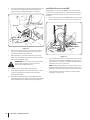
3. The two hydrostatic transmissions are equipped with a
bypass valve that will allow you to manually move the
tractor short distances.
4. Engage the transmission bypass valves by engaging the
parking brake. See Figure 3-2. The tractor will still not move
freely until the parking brake is released.
Parking Brake
Figure 3-2

12 Section 2— ASSembly & Set-Up
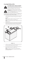
5. To release the parking brake, flip the seat forward and locate
the cotter pin and clevis pin that secure the dump valve
relief lever to the parking break handle. See Figure 3-3.
Clevis Pin
Dump Valve
Relief Lever
Cotter Pin
Figure 3-3
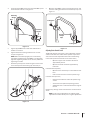
6. Remove the cotter pin from the clevis pin. Then slide the
clevis pin out of the relief lever. Be sure not to lose the
spacer on the inside of the relief lever.
7. With the dump valve relief lever free from the parking
break cable, release the parking brake and the tractor will
now move in freewheel mode.
WARNING! Do not tow the tractor, even with the
bypass valves engaged. Serious transmission
damage will result from doing so.
8. Carefully roll the tractor off the shipping pallet.
9. Reset the parking brake, and resintall the clevis pin, spacer,
cotter pin and dump valve relief lever back onto the
parking brake handle.
10. Remove the deck wash system nozzle adapter from the
manual bag and store for future use. Cut the wire tie holding
the chute deflector up and discard any packing material.
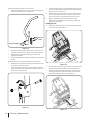
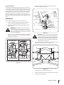
Install Roll Over Protective System (ROPS)
The Roll Over Protective System (ROPS) has not been installed
on your unit for shipping purposes. Using the hardware found in
the Roll Over Protective System container, install it on your unit
as follows:
1. Insert each of the lower section ROPS tubular posts into the
brackets welded to the tractor main frame. See Figure 3-4.
ROPS Lower
Sections
Carriage Bolt
Flat Washer Flat Washer
Reinforced Plate
Flange Lock Nut
Figure 3-4
2. Insert the hex screws (one per side) through the flat washer
then into the frame brackets and ROPS posts from the rear
toward the front. See Figure 3-4. Alternately from the front
toward the rear if access is restricted.
NOTE: The mounting hardware is accessible from the rear of
the machine with the use of extensions. Also, access can be
gained by reaching in from the sides over the tires fuel tanks.
3. Install the reinforced plates and flange lock nuts, but do
not tighten. See Figure 3-4.

13Section 2 — ASSembly & Set-Up
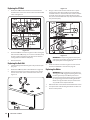
4. Install the upper ROPS section onto the lower ROPS “posts”.
Install the bolts and nuts. See Figure 3-5.
Bolt
Retaining
Washer
Lock Nuts
Bolt
Retaining
Washer
Figure 3-5
5. Tighten upper ROPS section bolts after both RH & LH
hardware is installed.
6. Tighten the frame mounting hardware to 80-90 lb.-ft.
torque. See Figure 3-4.
NOTE: Make sure tubular upright posts are absolutely
tight within welded bracket. If the ROPS is not absolutely
tight after tightening hardware to 80-90 ft-lbs, additional
tightening is needed.
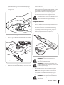
7. Route the nylon lanyard as shown in Figure 3-6. Be sure to
secure the lanyard to the retaining clip and clevis pin.
A
B
C
Figure 3-6
8. Move the upper ROPS section to the upright position, and
insert the locking pins with their retainer hairpin clips. See
Figure 3-7.
Locking Pin
Locking Pin
Retainer
Hairpin
Clips
Figure 3-7
Adjusting Drive Control Levers
The RH and LH drive control levers can be adjusted up or down
and fore-and-aft for the comfort of the operator. Proper drive
control lever and seat adjustment will result in the following:
In the neutral position with hands on the control levers,
• Operator’s upper arms should be relaxed and
approximately vertical.
• Operator’s forearms should be approximately
horizontal.
In the full forward position,
• Operator’s back should stay in contact with the seat
back.
• Control levers should not contact operator’s legs.
In the full reverse position,
• Control levers should not contact the operator’s legs
or torso.
• Set the seat to the preferred operating position.
• Adjustment lever is located under the front edge of
the seat.
Check factory settings of control levers for the conditions listed
above.
NOTE: If control lever adjustments are required, height
adjustments should be made prior to angular adjustments.

14 Section 2— ASSembly & Set-Up
To adjust the height of the drive control levers:
1. Remove the flange lock nuts that secure the carriage bolts
in the drive control levers. See Figure 3-8.
Flange Lock Nuts
Carriage
Bolts
Figure 3-8
2. Remove the carriage bolts from the drive control levers and
reposition to the second set of holes in the mounting block.
3. Reinstall the carriage bolts and flange lock nuts, and
tighten to 28-34 ft-lbs.
4. The same adjustments should be made to both sides of the
mower.
To adjust the front-to-rear angle of the drive control levers:
1. Remove the carriage bolt and flange lock nut from the slot
of one of the drive control levers.
2. Lift and swing that control lever upward until the slotted
hole in the lever bracket aligns with one of the holes in the
pivot bracket. See Figure 3-9.
Figure 3-9
3. From the inside insert the carriage boltthrough the control
lever slot and the hole of the pivot bracket. Secure with the
flange lock nut. See Figure 3-9.
4. Note the relative position of the control lever to the pivot
bracket, then repeat the previous steps to reposition the
other control lever in approximately the same position.
5. Refer to “Adjusting the Drive Control Levers” in the
Maintenance & Adjustments for instructions on the final
adjustment of the levers.
Installing the Seat
1. Remove the two flange lock nuts and shoulder bolts from
the seat bracket. See Figure 3-10.
Figure 3-10
2. Place the seat into position and secure the seat into place with
the previously removed hardware as shown in Figure 3-10.
3. Remove the shoulder screw and flange lock nut from the
the support cable and install the support cable with the
previously removed hardware. See Figure 3-11.
Figure 3-11

15Section 2 — ASSembly & Set-Up
4. Insert the wiring harness into the bottom of the seat as
shown in Figure 3-12.
Figure 3-12
NOTE: When the harness is connected, be sure to push the
excess wire from the wire harness into the seat box hole
before continuing.
Seat Adjustment
This tractor is equipped with an adjustable seat, which includes a
retractable seat belt assembly and an Operator Presence Sensor
(OPS). The OPS in the form of a switch, is integrated into the seat
bottom and is connected to the machine electrical system.
The seat can be adjusted forward and back and the arm rest can
be adjusted up and down.
To move the seat forward or back, locate the seat adjustment rod
under the seat. Push the rod to the left and slide the seat forward
or back into the desired position and release the rod when the
seat is in the desired position. See Figure 3-13.
Figure 3-13
To adjust the arm rest, lift the arm rest and rotate the block
adjustment into one of the four positions (0-3, 0 being the lowest
and 3 being the highest.) and lower the arm rest. See Figure 3-14.
Figure 3-14
The mechanical suspension mechanism (if equipped)
incorporates weight/ride adjustment controls for operators in
the 125 to 275 lb. weight range (turn the knob on the front of
the seat clockwise to increase the weight capacity and counter-
clockwise to decrease. See Figure 3-15.
Figure 3-15
NOTE: The seat base must be secured by the latch,
otherwise, the seat assembly could tilt forward. The
Operator Presence Sensor must be connected to the
electrical wiring harness.

16 Section 2— ASSembly & Set-Up
Connecting the Battery Cables
CALIFORNIA PROPOSITION 65 WARNING:
Battery posts, terminals, and related accessories
contain lead and lead compounds, chemicals known
to the State of California to cause cancer and
reproductive harm. Wash hands after handling.
CAUTION: When attaching battery cables, always
connect the POSITIVE (Red) wire to its terminal first,
followed by the NEGATIVE (Black) wire.
For shipping reasons, both battery cables on your equipment may
have been left disconnected from the terminals at the factory. To
connect the battery cables, proceed as follows:
1. Using the lever on the back of the seat frame, lift up on the
lever and tilt the seat forward locking it in place with the
seat prop.
NOTE: The positive battery terminal is marked Pos. (+). The
negative battery terminal is marked Neg. (–).
NOTE: If the positive battery cable is already attached, skip
ahead to step 2.
2. Remove the red boot, if present, from the positive battery
terminal and attach the red cable to the positive battery
terminal (+) with the bolt and hex nut. See Figure 3-16.
Figure 3-16
3. Position the red boot over the positive battery terminal to
insulate it and help protect it from corrosion.
4. Attach the black cable to the negative battery terminal (–)
with the bolt and hex nut. See Figure 3-16.
NOTE: If the battery is put into service after the date
shown on top/side of battery, charge the battery prior to
operating the tractor.

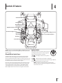
Controls & Features 4
17
Ignition Switch
PTO Switch
Digital Tachometer & Hour Meter
Throttle Control
Choke Knob
Parking Break Lever
Fuel Tank Cap
Cup Holder
Deck Height Index
Deck Lift Pedal
Deck Lift Release Lever
Accessory Switch Receptacles
RH & LH Drive Control Levers
Fuel Valve
Transmission Bypass Lever
Transmission Bypass Lever
NOTE: References to LEFT, RIGHT, FRONT, and REAR indicate that
position on the tractor when facing forward while seated in the
operator’s seat.
RH and LH Drive Control Levers
The RH and LH control levers are located on each side of the
operator’s seat. These hinged levers pivot outward to open
space to permit the operator to either sit in the tractor seat, or to
dismount the tractor. The levers must be fully opened out and in
the neutral position to start the tractor engine.
Each lever controls the respective RH or LH transmission. These
levers control all of the movements of the tractor. Driving and
steering utilizing these control levers is quite different from
conventional tractors, and will take some practice to master.
Refer to Operation for instructions on using the control levers.
Ignition Switch
The ignition switch is located on the LH console
to the right of the operator’s seat. The ignition
switch has three positions as follows:
STOP — The engine and electrical system is
turned off.
RUN — The tractor electrical system is energized.
START — The starter motor will turn over the engine. Release
the key immediately when the engine starts
NOTE: To prevent accidental starting and/or battery
discharge, remove the key from the ignition switch when
the tractor is not in use.

18 Section 4— controlS & FeatureS
Power Take-Off (PTO) Switch
The PTO switch is located on the LH console to
the left of the operator’s seat next to the ignition
switch.
The PTO switch operates the electric PTO clutch
mounted on the bottom of the engine crankshaft.
Pull the knob upward to engage the PTO clutch, or
push the knob downward to disengage the clutch.
The PTO switch must be in the “disengaged”
position when starting the engine.
Digital Tachometer and Hour Meter
0.0
The tachometer/hour meter panel is located on the LH console to
the left of the operator’s seat. The hour meter records the hours
that the tractor has been operated in the digital display. The
tachometer provides engine speed (RPM), and service reminders
(oil, lube) in the digital display.
The tachometer/hour meter is activated whenever the ignition
switch is turned to the “ON” position. Keep a record of the actual
hours of operation to assure all maintenance procedures are
completed according to the instructions in this manual and the
engine manual.
Throttle Control
The throttle control is located on the RH console to the right
of the operator’s seat. When set in a given position, a uniform
engine speed will be maintained. The throttle control moves
between the fast and slow positions.
Push the throttle control handle forward to increase the engine
speed. The tractor is designed to operate with the throttle
control in the fast position (full throttle) when the tractor is
being driven and the mower deck is engaged.
Pull the throttle control handle rearward to decrease the engine
speed.
Choke Knob
The choke knob is located on the right side of
the mower next to the operator’s seat. Pull the
knob out to choke the engine; push the knob in to
open the choke. Having the choke in the ON (up)
position helps the engine to start during initial start-up. During
normal operation the choke should be OFF (down).
CHOKE
Parking Brake Lever
The parking brake lever is located on the LH console to the
left of the operator’s seat. When pulled up it engages the
parking brake and when pushed down it releases the brake.
NOTE: If the forward and reverse neutral position when
engaging the parking brake, the engine will stop. The
parking brake must be placed in the engaged position
when starting the tractor engine.
Fuel Tank Cap
The fuel tank cap is located on the top of the fuel tank on the
left side of the seat. Turn the fill cap counter-clockwise to remove
and clockwise until it clicks three times to tighten. Always re-install
the fuel cap tightly onto the fuel tank after removing.
WARNING! Never fill the fuel tank when the engine
is running. If the engine is hot from recently running,
allow to cool for several minutes before refueling.
Highly flammable gasoline could splash onto the
engine and cause a fire.
Cup Holder
The cup holder is located on the LH console to the left of the
operator’s seat.
Seat Adjustment Lever (Not Shown)
The seat adjustment lever is located below the right of the
seat. The lever allows for adjustment forward or rearward of
the operator’s seat. Refer to the Assembly & Set-Up section for
instructions on adjusting the seat position.
Deck Height Index
4.50"
3.
50"
2.50"
1.
50"
4.75"
3.75"
2.75
"
1.75"
5"
4"
3"
2"
1"
3.25"
4.25"
2.25"
1.25"
The deck height index consists of several holes located on the
left of the foot platform. Each hole corresponds to a ⁄” change in
the deck height position ranging from 1” at the lowest notch to
5” at the highest notch.
Deck Lift Pedal
The deck lift pedal is located on the left front corner of the foot
platform, and is used to raise and lower the mower deck.
To raise the mowing deck to the transport position, push the pedal
all the way forward until the deck lock rod snaps into position. To
remove the deck from the transport position push forward on the
deck lift pedal and pull up on the deck lock rod. To position the
deck push the pedal all the way forward, remove the clevis pin and
reinsert it in the desired cutting height and slowly release pressure
on the pedal until you reach the clevis pin.
ON
PARK BRAKE
OFF
P

19Section 4 — controlS & FeatureS
Deck Lift Release Lever
The deck lift release lever is located on the left side of the
operator’s seat and is used to lock the deck in the transport
position. Press down on the deck lift pedal and lift up on the
deck lift release lever to release the deck.
Fuel Valve
The fuel valve is located on the fuel tank. The fuel valve can shut
off the flow of feul to the engine by turning the knob to the right.
To re-open the valve, turn the valve to the left.
Accessory Switch Receptacles
The three receptacles for
optional accessories are
on the RH console. See the
Attachments & Accessories
section for information. The
receptacles are for switches
for an optional electric deck
lift, lights and/or an auxiliary switch.
Transmission Bypass Levers
The transmission bypass levers (one for each the RH and LH
transmission) are located under the tractor on the front of each
transmission inside the rear wheels. The levers are connected to
a valve bracket that allows the levers to be controlled from the
parking brake.
When engaged the two valves open a bypass within the
hydrostatic transmissions. Refer to the Assembly & Set-Up
section for instructions on using the bypass feature.
AUX. LIGHTS
DECK
LIFT

Operation 5
20
Before Operating Your Machine
1. Before you operate the tractor, study this manual carefully
to familiarize yourself with the operation of all the
instruments and controls. It has been prepared to help you
operate and maintain your machine efficiently.
2. Fill the fuel tank with only clean, fresh, unleaded gasoline
with a pump sticker octane rating of 87 or higher. When
the fuel reaches ⁄” below the bottom of the fill neck, stop.
DO NOT OVERFILL. Space must be left for expansion.
3. Never use gasoline containing more than 10% ethanol or
methanol.
4. Check the engine oil level as instructed in the Engine
Operator’s manual.
5. Check the transmission oil level. The transmission oil
expansion reservoir is located beneath the operator’s
seat. Always wipe off the area around the reservoir fill
neck before checking the oil level to prevent dirt from
contaminating the oil. Remove the cap and make sure the
oil level is a 1/4” above the bottom of the reservoir. If the oil
level is low, fill with Castrol™ (Syntec®) Edge™.
6. Check the tire inflation pressures — 12 psi for the rear tires,
14 psi front tires.
NOTE: New tires are over-inflated in order to properly seat
the bead to the rim.
7. Check that all nuts, bolts and screws are tight.
8. Check the tension of the deck drive belts.
a. Remove the deck cover
b. The tension of the deck drive belts are maintained
by a spring mechanism that adjusts for wear and
stretch.
c. Examine the belts for cuts, fraying, and excessive
wear. Replace if any of these are detected.
d. Replace the deck cover.
9. Check if deck is level. When correctly adjusted the mower
deck should be level side to side, and the front of the deck
should be approximately ⁄” lower than the rear of deck.
If deck needs to be leveled, refer to the Maintenance &
Adjustments section.
10. Lubricate all pivot points listed in the Maintenance &
Adjustments section.
11. Adjust the seat for operator’s maximum comfort, visibility
and for maintaining complete control of the machine.
Refer to the Assembly & Set-Up section for instructions on
adjusting the seat.
Safety Interlock System
This machine is equipped with a safety interlock system for
the protection of the operator. If the interlock system should
ever malfunction, do not operate the machine. Contact your
authorized Cub Cadet Dealer.
• The safety interlock system prevents the engine from
cranking or starting unless the RH and LH drive control
levers are moved fully outward in the neutral position, the
parking brake is engaged, and the PTO is disengaged.
• To avoid sudden movement when disengaging the parking
brake, the safety interlock system will shut off the engine
if the RH and/or LH drive control levers are moved to a
position other than the fully out in the neutral position
when the parking brake is engaged.
• The safety interlock system will shut off the engine if the
operator leaves the seat before engaging the parking brake.
• The safety interlock system will shut off the engine if the
operator leaves the seat with the PTO engaged, regardless
of whether the parking brake is engaged.
NOTE: The PTO must be disengaged to restart the engine.
Starting the Engine
WARNING! This machine is equipped with a safety
interlock system designed for the protection of the
operator. Do not operate the machine if any part of
the interlock system is malfunctioning. Periodically
check the functions of the interlock system for
proper operation.
WARNING! For personal safety, the operator must
be sitting in the tractor seat when starting the
engine.
1. Open the fuel valve on the fuel tank.
2. Operator must be sitting in the tractor seat with both drive
control levers in the neutral/start position.
3. Engage the parking brake.
4. Make certain the PTO is in the disengaged (down) position.
5. Lift the choke knob into the on position.
NOTE: If the engine is warmed up, it may not be necessary
to choke the engine.
6. Move the throttle control to midway between the SLOW
and FAST positions.
Page is loading ...
Page is loading ...
Page is loading ...
Page is loading ...
Page is loading ...
Page is loading ...
Page is loading ...
Page is loading ...
Page is loading ...
Page is loading ...
Page is loading ...
Page is loading ...
Page is loading ...
Page is loading ...
Page is loading ...
Page is loading ...
Page is loading ...
Page is loading ...
Page is loading ...
Page is loading ...
Page is loading ...
Page is loading ...
Page is loading ...
Page is loading ...
-
 1
1
-
 2
2
-
 3
3
-
 4
4
-
 5
5
-
 6
6
-
 7
7
-
 8
8
-
 9
9
-
 10
10
-
 11
11
-
 12
12
-
 13
13
-
 14
14
-
 15
15
-
 16
16
-
 17
17
-
 18
18
-
 19
19
-
 20
20
-
 21
21
-
 22
22
-
 23
23
-
 24
24
-
 25
25
-
 26
26
-
 27
27
-
 28
28
-
 29
29
-
 30
30
-
 31
31
-
 32
32
-
 33
33
-
 34
34
-
 35
35
-
 36
36
-
 37
37
-
 38
38
-
 39
39
-
 40
40
-
 41
41
-
 42
42
-
 43
43
-
 44
44


Ask a question and I''ll find the answer in the document
Finding information in a document is now easier with AI
Related papers
-
Cub Cadet RZT L Series User manual
-
Cub Cadet 53TIEFJU050 User manual
-
Cub Cadet 53TWEHRA050 User manual
-
Cub Cadet 53TIHMTV050 User manual
-
-
-
-
-
-
Other documents
-
MTD 790 User manual
-
 Great Dane GSRKA1934S Owner's manual
-
Husqvarna M-ZT 52 User manual
-
 Great Dane 200466-GLKW1536S-GLKW1748S Owner's manual
-
Greenworks CRZ426 User guide
-
 National Mower I-TRIM Owner's manual
-
-
Energizer ENB130A Owner's manual
-
 National Mower I-TRIM Owner's manual
-
Agri-Fab LP46468 User manual


