Carrier 38QHC009DS series User manual
- Category
- Split-system air conditioners
- Type
- User manual
This manual is also suitable for

15C Inverter Series
Service Manual

CONTENTS
1. Precaution .................................................................................................................................................... 1
1.1 Safety Precaution .......................................................................................................................... 1
1.2 Warning ......................................................................................................................................... 1
2. Function ........................................................................................................................................................ 4
3. Dimension .................................................................................................................................................... 5
3.1 Indoor Unit ..................................................................................................................................... 5
3.2 Outdoor Unit .................................................................................................................................. 7
4. Wiring Diagram ............................................................................................................................................ 8
5. Refrigerant Cycle Diagram ....................................................................................................................... 10
6. Installation Details ...................................................................................................................................... 11
6.1 Wrench torque sheet for installation ............................................................................................ 11
6.2 Connecting the cables ................................................................................................................. 11
6.3 Pipe length and the elevation ..................................................................................................... 12
6.4 Installation for the first time ......................................................................................................... 13
6.5 Adding the refrigerant after running the system for many years ................................................ 14
6.6 Re-installation while the indoor unit need to be repaired ........................................................... 14
6.7 Re-installation while the outdoor unit need to be repaired ......................................................... 15
7. Operation Characteristics ......................................................................................................................... 17
8. Electronic function .................................................................................................................................... 18
8.1 Abbreviation ................................................................................................................................ 18
8.2 Display function ........................................................................................................................... 18
8.3 Main Protection ........................................................................................................................... 19
8.4 Operation Modes and Functions ................................................................................................. 20
9. Troubleshooting ......................................................................................................................................... 27
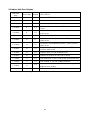
9.1 Indoor Unit Error Display ............................................................................................................. 28
9.2 Trouble shooting.......................................................................................................................... 29

1
1. Precaution
1.1 Safety Precaution
To prevent injury to the user or other
people and property damage, the following
instructions must be followed.
Incorrect operation due to ignoring
instruction will cause harm or damage.
Before service the unit, be sure to
read this service manual at first.
1.2 Warning
Installation
Do not use a defective or underrated
circuit breaker. Use this appliance on a
dedicated circuit.
There is risk of fire or electric shock.
For electrical work, contact the dealer,
seller, a qualified electrician, or an
authorized service center.
Do not disassemble or repair the product,
there is risk of fire or electric shock.
Always ground the product.
There is risk of fire or electric shock.
Install the panel and the cover of
control box securely.
There is risk of fire of electric shock.
Always install a dedicated circuit and
breaker.
Improper wiring or installation may cause fore
or electric shock.
Use the correctly rated breaker of
fuse.
There is risk of fire or electric shock.
Do not modify or extend the power
cable.
There is risk of fire or electric shock.
Do not install, remove, or reinstall the
unit by yourself (customer).
There is risk of fire, electric shock, explosion,
or injury.
Be caution when unpacking and
installing the product.
Sharp edges could cause injury, be especially
careful of the case edges and the fins on the
condenser and evaporator.
For installation, always contact the
dealer or an authorized service center.
Do not install the product on a
defective installation stand.
Be sure the installation area does not
deteriorate with age.
If the base collapses, the air conditioner could
fall with it, causing property damage, product
failure, and personal injury.
Do not let the air conditioner run for a
long time when the humidity is very high
and a door or a window is left open.
Take care to ensure that power cable
could not be pulled out or damaged during
operation.
There is risk of fire or electric shock.
Do not place anything on the power
cable.
There is risk of fire or electric shock.
Do not plug or unplug the power
supply plug during operation.
There is risk of fire or electric shock.
Do not touch (operation) the product
with wet hands.
Do not place a heater or other
appliance near the power cable.
There is risk of fire and electric shock.
Do not allow water to run into
electrical parts.
It may cause fire, failure of the product, or
electric shock.
Do not store or use flammable gas or
combustible near the product.
There is risk of fire or failure of product.
Do not use the product in a tightly
closed space for a long time.
Oxygen deficiency could occur.
When flammable gas leaks, turn off
the gas and open a window for ventilation
before turn the product on.
If strange sounds or smoke comes

2
from product, turn the breaker off or
disconnect the power supply cable.
There is risk of electric shock or fire.
Stop operation and close the window
in storm or hurricane. If possible, remove
the product from the window before the
hurricane arrives.
There is risk of property damage, failure of
product, or electric shock.
Do not open the inlet grill of the
product during operation. (Do not touch the
electrostatic filter, if the unit is so equipped.)
There is risk of physical injury, electric shock,
or product failure.
When the product is soaked, contact
an authorized service center.
There is risk of fire or electric shock.
Be caution that water could not enter
the product.
There is risk of fire, electric shock, or product
damage.
Ventilate the product from time to
time when operating it together with a stove
etc.
There is risk of fire or electric shock.
Turn the main power off when
cleaning or maintaining the product.
There is risk of electric shock.
When the product is not be used for a
long time, disconnect the power supply plug
or turn off the breaker.
There is risk of product damage or failure, or
unintended operation.
Take care to ensure that nobody
could step on or fall onto the outdoor unit.
This could result in personal injury and
product damage.
CAUTION
Always check for gas (refrigerant)
leakage after installation or repair of
product.
Low refrigerant levels may cause failure of
product.
Install the drain hose to ensure that
water is drained away properly.
A bad connection may cause water leakage.
Keep level even when installing the
product.
It can avoid vibration of water leakage.
Do not install the product where the
noise or hot air from the outdoor unit could
damage the neighborhoods.
It may cause a problem for your neighbors.
Use two or more people to lift and
transport the product.
Do not install the product where it will
be exposed to sea wind (salt spray) directly.
It may cause corrosion on the product.
Corrosion, particularly on the condenser and
evaporator fins, could cause product
malfunction or inefficient operation.
Operational
Do not expose the skin directly to
cool air for long time. (Do not sit in the
draft).
Do not use the product for special
purposes, such as preserving foods, works
of art etc. It is a consumer air conditioner,
not a precision refrigerant system.
There is risk of damage or loss of property.
Do not block the inlet or outlet of air
flow.
Use a soft cloth to clean. Do not use
harsh detergents, solvents, etc.
There is risk of fire, electric shock, or damage
to the plastic parts of the product.
Do not touch the metal parts of the
product when removing the air filter. They
are very sharp.
Do not step on or put anything on the
product. (outdoor units)
Always insert the filter securely.
Clean the filter every two weeks or more
often if necessary.
A dirty filter reduces the efficiency of the air
conditioner and could cause product
malfunction or damage.
Do not insert hands or other objects

3
through air inlet or outlet while the product
is operated.
Do not drink the water drained from
the product.
Use a firm stool or ladder when
cleaning or maintaining the product.
Be careful and avoid personal injury.
Replace the all batteries in the remote
control with new ones of the same type. Do
not mix old and new batteries or different
types of batteries.
There is risk of fire or explosion.
Do not recharge or disassemble the
batteries. Do not dispose of batteries in a
fire.
They may burn of explode.
If the liquid from the batteries gets
onto your skin or clothes, wash it well with
clean water. Do not use the remote of the
batteries have leaked.

4
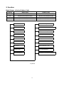
2. Function
Model Names of Indoor/Outdoor Units
Capacity
Indoor units
Outdoor units
9k
42QHC009DS/42QHC009ES
38QHC009DS/38QHC009ES
12k
42QHC012DS/42QHC012ES
38QHC012DS/38QHC012ES
18k
42QHC018DS/42QHC018ES
38QHC018DS/38QHC018ES
24k
42QHC024DS/42QHC024ES
38QHC024DS/38QHC024ES
Cold catalyst filter
Silver Ico Filter(O)
Vitamin C Filter(O)
3M HAM Filter(O)
Bio Filter(O)
Golden Fin(O)
Super Ionizer(O)
Compressor Crankcase Heater(O)Self-cleaning (O)
Louver Position Memory Function
Refrigerant Leakage Detect
Self-diag. Function
Hydrophilic Aluminum Fin
Anti-rust Cabinet
Valve Protection Cover
PTC Heating Belt(O)
Filter 2 ways of drainage
O:optional

5
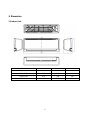
3. Dimension
3.1 Indoor Unit
Model
W
D
H
42QHC009
730
192
291
42QHC012
812
192
300
42QHC018
973
218
319
42QHC024
1082
225
338

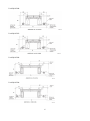
6
For 42QHC009,
For 42QHC012,
For 42QHC018,
For 42QHC024,

7
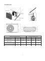
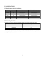
3.2 Outdoor Unit
Outdoor Unit Dimentsion(mm)
Mounting Dimentsion(mm)
Outdoor Unit
W
H
D
A
B
38QHC009DS
700
550
275
450
267
38QHC012DS
38QHC009ES
770
555
300
487
298
38QHC018DS
38QHC012ES/38QHC018ES
800
554
333
515
340
38QHC024DS/38QHC024ES
845
702
363
540
376

8
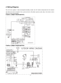
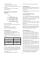
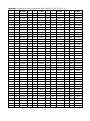
4. Wiring Diagram
The “W” is for system 1 watt consumption standby control, the “W” cable is the power line for outdoor
unit. When the unit is turned off, the system will turn off outdoor power by the relay in the indoor unit to
reduce power consumption.
Outdoor (38QHC009/38QHC012)
Outdoor (38QHC018/38QHC024)

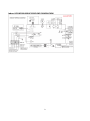
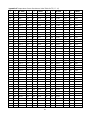
9
Indoor (42QHC009/42QHC012/42QHC018/42QHC024)

10
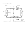
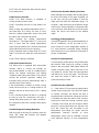
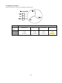
5. Refrigerant Cycle Diagram
LIQUID SIDE
GAS SIDE
HEAT
EXCHANGE
(EVAPORATOR)
HEAT
EXCHANGE
(CONDENSER)
COMPRESSOR
2-WAY VALVE
3-WAY VALVE
4-WAY VALVE
COOLING
HEATING
T2 Evaporator
temp. sensor
T1 Room temp.
sensor
ACCUMULATOR
INDOOR OUTDOOR
CHECK VALVE
(Heating Model only)
CAPILIARY TUBE

11
6. Installation Details
6.1 Wrench torque sheet for installation
Outside diameter
Torque
Additional tightening torque
mm
inch
N.cm
N.cm
Ф6.35
1/4
1500(153kgf.cm)
1600(163kgf.cm)
Ф9.52
3/8
2500(255kgf.cm)
2600(265kgf.cm)
Ф12.7
1/2
3500(357kgf.cm)
3600(367kgf.cm)
Ф15.9
5/8
4500(459kgf.cm)
4700(479kgf.cm)
Ф19
3/4
6500(663kgf.cm)
6700(683kgf.cm)
6.2 Connecting the cables
The power cord of connect should be selected according to the following specifications sheet.
Rated current of appliance
Nominal cross-sectional area (mm²)
>3 and ≤6
0.75
>6 and ≤10
1
>10 and ≤16
1.5
>16 and ≤25
2.5
The cable size and the current of the fuse or switch are determined by the maximum current indicated
on the nameplate which located on the side panel of the unit. Please refer to the nameplate before
selecting the cable, fuse and switch.

12
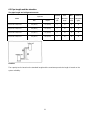
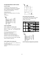
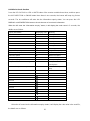
6.3 Pipe length and the elevation
The pipe length and refrigerant amount:
Model
Pipe size
Standard
length
(m)
Max.
Elevation
B (m)
Max.
Length
A (m)
Additional
refrigerant
(g/m)
Gas
Liquid
42QHC009+ 38QHC009
3/8’’(Ф9.52)
1/4’’(Ф6.35)
5
10
25
15
42QHC012+ 38QHC012
3/8’’(Ф9.52)
1/4’’(Ф6.35)
5
10
25
15
42QHC018+ 38QHC018
1/2’’(Ф12.7)
1/4’’(Ф6.35)
5
20
30
15
42QHC024+ 38QHC024
5/8’’(Ф15.9)
3/8’’(Ф9.52)
5
20
40
30
Caution:
The capacity test is based on the standard length and the maximum permissive length is based on the
system reliability.

13
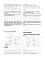
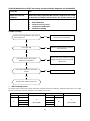
6.4 Installation for the first time
Air and moisture in the refrigerant system have
undesirable effects as below:
● Pressure in the system rises.
● Operating current rises.
● Cooling or heating efficiency drops.
● Moisture in the refrigerant circuit may
freeze and block capillary tubing.
● Water may lead to corrosion of parts in the
refrigerant system.
Therefore, the indoor units and the pipes
between indoor and outdoor units must be leak
tested and evacuated to remove gas and
moisture from the system.
Gas leak check (Soap water method):
Apply soap water or a liquid neutral
detergent on the indoor unit connections or
outdoor unit connections by a soft brush to
check for leakage of the connecting points of
the piping. If bubbles come out, the pipes have
leakage.
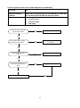
1. Air purging with vacuum pump
1) Completely tighten the flare nuts of the
indoor and outdoor units, confirm that both
the 2-way and 3-way valves are set to the
closed position.
2) Connect the charge hose with the push pin
of handle lo to the 3-way valves gas service
port..
3) Connect the charge hose of handle hi
connection to the vacuum pump.
4) Fully open the handle Lo of the manifold
valve.
5) Operate the vacuum pump to evacuate.
6) Make evacuation for 30 minutes and check
whether the compound meter indicates
-0.1Mpa. If the meter does not indicate
-0.1Mpa after pumping 30 minutes, it
should be pumped 20 minutes more. If the
pressure can’t achieve -0.1Mpa after
pumping 50 minutes, please check if there
are some leakage points.
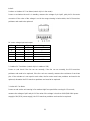
Fully close the handle Lo valve of the manifold
valve and stop the operation of the vacuum
pump. Confirm that the gauge needle does not
move (approximately 5 minutes after turning off
the vacuum pump).
7) Turn the flare nut of the 3-way valves about
45° counterclockwise for 6 or 7seconds
after the gas
coming out, then tighten the flare nut again.
Make sure the pressure display in the pressure
indicator is a little higher than the atmosphere
pressure. Then remove the charge hose from
the 3 way valve.
8) Fully open the 2 way valve and 3 way valve
and securely tighten the cap of the 3 way
valve.
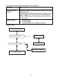
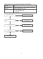
2. Adding the refrigerant if the pipe
length >5m
Procedure:
1). Connect the charge hose to the charging
cylinder, open the 2-way valve and the 3-way
valve.
Connect the charge hose which you

14
disconnected from the vacuum pump to the
valve at the bottom of the cylinder. If the
refrigerant is R410A, make the cylinder bottom
up to ensure the liquid charge.
2). Purge the air from the charge hose.
Open the valve at the bottom of the cylinder
and press the check valve on the charge set to
purge the air (be careful of the liquid
refrigerant).
3) Put the charging cylinder onto the electronic
scale and record the weight.
4) Operate the air conditioner at the cooling
mode.
5) Open the valves (Low side) on the charge set
and charge the system with liquid refrigerant.
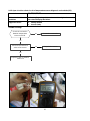
6).When the electronic scale displays the proper
weight (refer to the table), disconnect the charge
hose from the 3-way valve’s service port
immediately and turn off the air conditioner before
disconnecting the hose.
7). Mount the valve stem caps and the service
port
Use torque wrench to tighten the service port
cap to a torque of 18N.m.
Be sure to check for gas leakage.
6.5 Adding the refrigerant after running
the system for many years
Procedure:
1). Connect the charge hose to the 3-way service
port, open the 2-way valve and the 3-way valve.
Connect the charge hose to the valve at the
bottom of the cylinder. If the refrigerant is
R410A, make the cylinder bottom up to ensure
liquid charge.
2). Purge the air from the charge hose.
Open the valve at the bottom of the cylinder
and press the check valve on the charge set to
purge the air (be careful of the liquid
refrigerant).
3) Put the charging cylinder onto the electronic
scale and record the weight.
4) Operate the air conditioner at the cooling
mode.
5) Open the valves (Low side) on the charge set
and charge the system with liquid refrigerant.
6).When the electronic scale displays the proper
weight (refer to the gauge and the pressure of the
low side), disconnect the charge hose from the
3-way valve’s service port immediately and turn
off the air conditioner before disconnecting the
hose.
7). Mount the valve stem caps and the service
port
Use torque wrench to tighten the service port
cap to a torque of 18N.m.
Be sure to check for gas leakage.
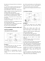
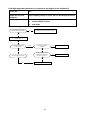
6.6 Re-installation while the indoor unit
need to be repaired
1. Collecting the refrigerant into the outdoor
unit
Procedure
1). Confirm that both the 2-way and 3-way valves
are set to the opened position
Remove the valve stem caps and confirm that the
valve stems are in the opened position.

15
Be sure to use a hexagonal wrench to operate the
valve stems.
2). Connect the charge hose with the push pin of
handle lo to the 3-way valves gas service port.
3). Air purging of the charge hose.
Open the handle Lo valve of the manifold valve
slightly to purge air from the charge hose for 5
seconds and then close it quickly.
4). Set the 2-way valve to the close position.
5). Operate the air conditioner at the cooling cycle
and stop it when the gauge indicates 0.1MPa.
6). Set the 3-way valve to the closed position
immediately
Do this quickly so that the gauge ends up
indicating 0.3 to 0.5Mpa.
Disconnect the charge set, and tighten the 2-way
and 3-way valve’s stem nuts.
Use a torque wrench to tighten the 3-way valves
service port cap to a torque of 18N.m.
Be sure to check for gas leakage.
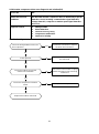
6.7 Re-installation while the outdoor unit
need to be repaired
1. Evacuation for the whole system
Procedure:
1). Confirm that both the 2-way and 3-way
valves are set to the opened position.
2). Connect the vacuum pump to 3-way valve’s
service port.
3). Evacuation for approximately one hour.
Confirm that the compound meter indicates
-0.1Mpa.
4). Close the valve (Low side) on the charge set,
turn off the vacuum pump, and confirm that the
gauge needle does not move (approximately 5
minutes after turning off the vacuum pump).
5). Disconnect the charge hose from the vacuum
pump.
2. Refrigerant charging
Procedure:
1). Connect the charge hose to the charging
cylinder, open the 2-way valve and the 3-way
valve
Connect the charge hose which you
disconnected from the vacuum pump to the
valve at the bottom of the cylinder. If the
refrigerant is R410A, make the cylinder bottom
up to ensure liquid charge.
2). Purge the air from the charge hose
Open the valve at the bottom of the cylinder
and press the check valve on the charge set to
purge the air (be careful of the liquid
refrigerant).
3) Put the charging cylinder onto the electronic
scale and record the weight.
4). Open the valves (Low side) on the charge set
and charge the system with liquid refrigerant
If the system cannot be charge with the specified
amount of refrigerant, or can be charged with a
little at a time (approximately 150g each time) ,
operating the air conditioner in the cooling cycle;
however, one time is not sufficient, wait
approximately 1 minute and then repeat the
procedure.
5).When the electronic scale displays the proper
weight, disconnect the charge hose from the
3-way valve’s service port immediately

16
If the system has been charged with liquid
refrigerant while operating the air conditioner,
turn off the air conditioner before disconnecting
the hose.
6). Mounted the valve stem caps and the service
port. Use torque wrench to tighten the service
port cap to a torque of 18N.m.
Be sure to check for gas leakage

17
7. Operation Characteristics
Mode
Temperature
Cooling operation
Heating
operation
Room temperature
18℃~32℃
0℃~27℃
Outdoor temperature
-15℃~46℃
(For the models with low temperature cooling
system)
-15℃~24℃
CAUTION:
1. If the air conditioner is used beyond the above conditions, certain safety protection features
may come into operation and cause the unit to operate abnormally.
2. The room relative humidity should be less than 80%. If the air conditioner operates beyond this
figure, the surface of the air conditioner may attract condensation. Please set the vertical air flow
louver to its maximum angle (vertically to the floor), and set HIGH fan mode.
3. The optimum performance will be achieved during this operating temperature zone.

18
8. Electronic function
8.1 Abbreviation
T1: Indoor room temperature
T2: Coil temperature of evaporator
T3: Coil temperature of condenser
T4: Outdoor ambient temperature
T5: Compressor discharge temperature
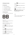
8.2 Display function
7.2.1 Icon explanation on indoor display board.
Digital display:
Displays the temperature settings when the air
conditioner is operational.
Displays the room temperature in FAN mode.
Displays the self-diagnostic codes.
Dispalys ‘ ’ for three seconds when Timer
ON, Fresh, Swing, Turbo or Silence feature is
activated.
Dispalys ‘ ’ for three seconds when Fresh,
Swing, Turbo or Silence feature is cancelled.
Dispalys ‘ ’ under deforsting operation.
Dispalys ‘ ’ when anti-cold air feature is
activated under heating mode.
Dispalys ‘ ’ during self clean operation (if
aplicable).
Dispalys ‘ ’ under 8 heating operation (if
aplicable).
When ECO function(optional) is actived,the
“ ” illuminates gradually one by one as
In one second interval.
NOTE:
A guide on using the infrared remote is not
included in this literature package.
Page is loading ...
Page is loading ...
Page is loading ...
Page is loading ...
Page is loading ...
Page is loading ...
Page is loading ...
Page is loading ...
Page is loading ...
Page is loading ...
Page is loading ...
Page is loading ...
Page is loading ...
Page is loading ...
Page is loading ...
Page is loading ...
Page is loading ...
Page is loading ...
Page is loading ...
Page is loading ...
Page is loading ...
Page is loading ...
Page is loading ...
Page is loading ...
Page is loading ...
-
 1
1
-
 2
2
-
 3
3
-
 4
4
-
 5
5
-
 6
6
-
 7
7
-
 8
8
-
 9
9
-
 10
10
-
 11
11
-
 12
12
-
 13
13
-
 14
14
-
 15
15
-
 16
16
-
 17
17
-
 18
18
-
 19
19
-
 20
20
-
 21
21
-
 22
22
-
 23
23
-
 24
24
-
 25
25
-
 26
26
-
 27
27
-
 28
28
-
 29
29
-
 30
30
-
 31
31
-
 32
32
-
 33
33
-
 34
34
-
 35
35
-
 36
36
-
 37
37
-
 38
38
-
 39
39
-
 40
40
-
 41
41
-
 42
42
-
 43
43
-
 44
44
-
 45
45


Carrier 38QHC009DS series User manual
- Category
- Split-system air conditioners
- Type
- User manual
- This manual is also suitable for
Ask a question and I''ll find the answer in the document
Finding information in a document is now easier with AI
Related papers
Other documents
-
mundoclima Series MUPR-H6 User manual
-
-
Midea MOA01-09HFN1 User manual
-
Klimaire KSIN024-H215 -O / -I User manual
-
CASPER LC Series Air Conditioner User guide
-
Airwell AWAU-YMF024-H61 User manual
-
 PIONEER Air Conditioner WYS012GMFI22RL User guide
-
-
-
Airwell AWSI-HMF009-N12 User manual
