Page is loading ...

Thermostats
Frost Protection Thermostat Type 5312-2
Mounting and
Operating Instructions
EB 5207 EN
Edition September 2008
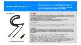
Fig. 1 · Type 5312-2 Frost Protection Thermostat

2 EB 5207 EN
DANGER!
DANGER indicates a hazardous situation
which, if not avoided, will result in death or
serious injury.
NOTICE
NOTICE indicates a property damage
message.
Note: Supplementary explanations, infor
-
mation and tips
Definitions of the signal words used in these instructions

1 General safety instructions
For your own safety, follow these instructions concerning the mounting, start-up and opera
-
tion of the thermostat:
4
The thermostat may only be mounted, started up or operated by trained and experienced
personnel familiar with the product.
According to these Mounting and Operating Instructions, trained personnel refers to
individuals who are able to judge the work they are assigned to and recognize possible
dangers due to their specialized training, their knowledge and experience as well as their
knowledge of the relevant standards.
4
On wiring and connecting the thermostat, you are required to observe the VDE
regulations and the regulations of the local power suppliers. Therefore, this type of work
must only be performed by trained personnel.
To avoid damage to any equipment, the following also applies:
4
Proper shipping and appropriate storage are assumed.
Note:
The device with a CE marking fulfills the requirements of the Directives 89/336/EEC.
The Declaration of Conformity is available on request.
EB 5207 EN 3
General safety instructions

2 Design and principle of
operation
The Type 5312-2 Frost Protection Thermo
-
stat fulfills the function of a temperature
monitor:
The double-throw switch is triggered if the
temperature at the sensor rises above the
adjusted set point. When the temperature
falls below the set point, the switch is auto
-
matically reset.
2.1 Technical data
Type 5312-2
Set point range –10 to +12 °C
Function Temperature monitor (TM)
Sensor Copper capillary, approx.
6 m in length, already
sensitive in partial ranges of
approx. 0.3 m
Switching
differential
Approx. 1 K
Switching point
accuracy
±
0.12 K
Temperature
Medium Max. +200 °C
Housing –15 to +55 °C
Switching element Microswitch, 1 changeover
contact
Contact rating
At 24–250 V~
15 (8) A with resistive load
2 A with cos
ϕ
= 0.6
At 24 V~ Min. 150 mA
Housing Sheet steel, degree of
protection IP 40
2.2 Ambient temperature
The thermostat is calibrated for an ambient
temperature of 22 °C.
At higher ambient temperatures, the switch
-
ing point is reduced by 0.08 %/K.
The switching points are raised at lower am
-
bient temperatures.
4 EB 5207 EN
Design and principle of operation

3 Installation
NOTICE!
On installing the thermostat, follow the in
-
structions described below to prevent dam
-
age to the thermostat and to ensure it can
function properly:
–
Only use with non-corrosive media.
–
Do not bend the capillary. The smallest
bending radius must not be smaller than
5 mm.
–
The temperature at the housing must be
at least as high as the adjusted value,
but must not be higher than 55 °C.
–
Mount the housing as close to the point
of measurement as possible since the
capillary is sensitive along its entire
length.
Note: A broken capillary is indicated when
the temperature falls below the set point.
To position the capillary properly at the out-
let of the heater battery, mounting clamps
are required (not included in the scope of
delivery).
Any mounting position can be chosen.
4 Electrical connection
Risk of electric shock!
On connecting the thermostat, you
are required to observe the relevant
regulations, especially VDE 0100.
1. Open the housing.
2. Route the connecting lead (
∅
5 to 10 mm,
max. 2.5 mm² wire cross-section)
through the cable gland in the housing
and connect it to the terminals according
to the wiring plan (Fig. 2).
3. Route the ground wire to the PE terminal
of the housing.
4. Close the housing.
EB 5207 EN 5
Installation
2
1
4
Fig. 2 · Wiring plan

5 Set point adjustment
Use a screwdriver to adjust the required set
point temperature at the adjustment screw
according to the scale.
6 Dimensions in mm
6 EB 5207 EN
Set point adjustment
105
46.5
39.5
43
77
25
27
Ø5.5
M20x1.5
Ø41
112
27
22
55
M5
10
6
Adjustment
screw

EB 5207 EN 7

SAMSON AG · MESS- UND REGELTECHNIK
Weismüllerstraße 3 · 60314 Frankfurt am Main · Germany
Phone: +49 69 4009-0 · Fax: +49 69 4009-1507
Internet: http://www.samson.de
EB 5207 EN
2008-09
/