
LP GAS CONVERSION INSTRUCTIONS
For WCG, MGC, KCGS and ICS5/6 Model Series
INSTRUCTIONS DE CONVERSION - GAZ PROPANE
Pour séries de modèles WCG, MGC, KCGS et ICS5/6
W10733303A
Table of Contents/Table des matières
COOKTOP SAFETY........................................................................2
Tools and Parts ............................................................................3
Convert from Natural Gas to LP Gas...........................................3
Convert from LP Gas to Natural Gas...........................................6
Lighting the Electronic Igniters ....................................................9
Flame Height Adjustment.............................................................9
Complete Burner Adjustment ....................................................10
SÉCURITÉ DE LA TABLE DE CUISSON ....................................11
Outillage et pièces......................................................................12
Conversion de gaz naturel à propane........................................13
Conversion de propane à gaz naturel........................................16
Allumeurs électroniques - allumage...........................................18
Réglage de la taille des flammes ...............................................19
Achever le réglage des brûleurs.................................................20
IMPORTANT:
Installer: Leave installation instructions with the homeowner.
Homeowner: Keep installation instructions for future reference.
IMPORTANT :
Installateur : Remettre les instructions d'installation au propriétaire.
Propriétaire : Conserver les instructions d'installation pour référence ultérieure.

2
COOKTOP SAFETY
You can be killed or seriously injured if you don't immediately
You
can be killed or seriously injured if you don't
follow
All safety messages will tell you what the potential hazard is, tell you how to reduce the chance of injury, and tell you what can
happen if the instructions are not followed.
Your safety and the safety of others are very important.
We have provided many important safety messages in this manual and on your appliance. Always read and obey all safety
messages.
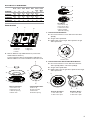
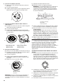
This is the safety alert symbol.
This symbol alerts you to potential hazards that can kill or hurt you and others.
All safety messages will follow the safety alert symbol and either the word “DANGER” or “WARNING.”
These words mean:
follow instructions.
instructions.
DANGER
WARNING
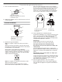
WARNING: If the information in this manual is not followed exactly, a fire or explosion
may result causing property damage, personal injury or death.
– Do not store or use gasoline or other flammable vapors and liquids in the vicinity of this
or any other appliance.
– WHAT TO DO IF YOU SMELL GAS:
•
Do not try to light any appliance.
•
Do not touch any electrical switch.
•
Do not use any phone in your building.
•
Immediately call your gas supplier from a neighbor's phone. Follow the gas supplier's
instructions.
•
If you cannot reach your gas supplier, call the fire department.
– Installation and service must be performed by a qualified installer, service agency or
the gas supplier.
WARNING: Gas leaks cannot always be detected by smell.
Gas suppliers recommend that you use a gas detector approved by UL or CSA.
For more information, contact your gas supplier.
If a gas leak is detected, follow the “What to do if you smell gas” instructions.
In the State of Massachusetts, the following installation instructions apply:
■
Installations and repairs must be performed by a qualified or licensed contractor, plumber, or gasfitter qualified or licensed by
the State of Massachusetts.
■
If using a ball valve, it shall be a T-handle type.
■
A flexible gas connector, when used, must not exceed 3 feet.

3
Tools and Parts
Gather the required tools and parts necessary for correct LP gas
conversion.
Tools needed
■ Flat-blade screwdriver
■ ³⁄₃₂" (#0 [2.0 mm]) flat-blade screwdriver (screwdriver shaft
must be a minimum of 2" [5.1 cm] long)
■ Adjustable wrench
■ 7.0 mm nut driver
■ 7.0 mm wrench
■ T10 Torx
®†
adapter
Parts needed
For models KCGS550ESS, KCGS556ESS, KCGS950ESS and
KCGS956ESS use the following parts:
■ LP orifice package (W10676662)
■ Conversion instructions (W10597146A)
For all other models use the following parts:
■ LP orifice package (W10676661)
■ Conversion instructions (W10597146A)
High Altitude Conversion
To convert the cooktop for elevations above 6,560 ft (1999.5 m),
order a High Altitude Conversion Kit.
For models KCGS550ESS, KCGS556ESS, KCGS950ESS and
KCGS956ESS use the following parts:
■ Part Number W10679116 - LP high altitude
■ Part Number W10679118 - Natural gas high altitude
For all other models use the following parts:
■ Part Number W10679114 - LP high altitude
■ Part Number W10679113 - Natural gas high altitude
To order, see the “Assistance or Service” section of the User Guide.
IMPORTANT: Gas conversions from Natural gas to LP gas must
be done by a qualified installer. Before proceeding with
conversion, shut off the gas supply to the cooktop prior to
disconnecting the electrical power.
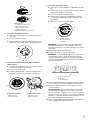
Convert from Natural Gas to LP Gas
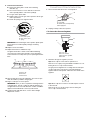
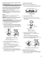
1. Turn manual shutoff valve to the closed position.
2. Unplug cooktop or disconnect power.
To Convert Gas Pressure Regulator
3. Determine the type of regulator you have:
Style 1: The cap has a slot and “NAT” printed on it.
Remove access cap by using a flat-blade screwdriver or coin,
turning the access cap counterclockwise.
†®TORX is a registered trademark of Acument Intellectual Properties, LLC.
WARNING
This conversion kit shall be installed by a
qualified service agency in accordance
with the manufacturer's instructions and
all applicable codes and requirements of
the authority having jurisdiction. If the
information in these instructions is not
followed exactly, a fire, explosion or
production of carbon monoxide may
result causing property damage, personal
injury or loss of life. The qualified service
agency is responsible for the proper
installation of this kit. The installation is
not proper and complete until the
operation of the converted appliance is
checked as specified in the
manufacturer's instructions supplied with
this kit.
A. To cooktop
B. Shutoff valve (closed position)
C. Gas supply line
A. Access cap
B. Rear of cooktop
C. Gas pressure regulator
D. Gas flow
WARNING
Explosion Hazard
Use a new CSA International approved gas supply line.
Install a shut-off valve.
Securely tighten all gas connections.
If connected to LP, have a qualified person make sure
gas pressure does not exceed 14" (36 cm) water
column.
Examples of a qualified person include:
licensed heating personnel,
authorized gas company personnel, and
authorized service personnel.
Failure to do so can result in death, explosion, or fire.
A
B
C
A
B
C
D

4
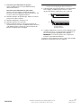
The gas pressure regulator has 2 settings that are stamped
on either side of the cap. Turn the cap and reinstall into
regulator with the stamp “LP” visible from the outside of the
regulator.
Style 2: The cap does not have a slot and requires a wrench
to be removed.
Remove the access cap by using a wrench, turning the
access cap counterclockwise.
Remove spring retainer from the cap by pushing against the
flat side of the spring retainer. Look at the spring retainer to
locate the “NAT” or “LP” position. Turn over the spring
retainer so the “LP” is showing on the bottom. Snap the
spring retainer back into the cap. Reinstall the cap onto the
regulator.
4. Test the gas pressure regulator and gas supply line.
The regulator must be checked at a minimum 1" (2.5 cm)
water column above the set pressure. The inlet pressure to
the regulator should be as follows for operation and checking
the regulator setting:
LP Gas:
Minimum pressure 10" (25.4 cm) W.C.P.
Supply pressure 14" (35.5 cm) W.C.P.
Gas Supply Pressure Testing
Line pressure testing above ½ psi gauge (14" WCP)
The cooktop and its individual shutoff valve must be
disconnected from the gas supply piping system during any
pressure testing of that system at test pressures in excess of
½ psi (3.5 kPa).
Line pressure testing at ½ psi gauge (14" WCP) or lower
The cooktop must be isolated from the gas supply piping
system by closing its individual manual shutoff valve during
any pressure testing of the gas supply piping system at test
pressures equal to or less than ½ psi (3.5 kPa).
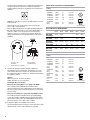
5. If the burner grates are installed, remove them.
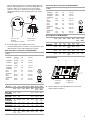
Use the following charts to match the correct gas orifice spud
with the burner location and model being converted.
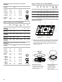
LP Gas Orifice Spud Chart for Kit W10676661
Burner Models for Kit W10676661
LP Gas Orifice Spud Chart for Kit W10676662
A. Access cap
B. Gasket
C. Gas pressure regulator
D. LP position
E. NAT position
A
B
CDE
Burner
Rating
Color Stamp (A) Size
5,000 BTU Green 66 0.66 mm
7,000 BTU White 75 0.75 mm
8,000 BTU Orange 79 0.79 mm
11,000 BTU Red 97 0.97 mm
13,000 BTU Yellow 108 1.08 mm
16,000 BTU Pink 115 1.15 mm
12,000 BTU
Inner
Outer
Brown
Brown
85
48
0.85 mm
0.48 mm
A. Size stamp
Model No. Left
Front
Left
Rear
Center
Inner
Center
Outer
Right
Rear
Right
Front
WCG51US0D
MGC7430D
ICS500DS00
66
Green
108
Yell ow
N/A N/A 97
Red
75
White
WCG75US0D
MGC9530D
66
Green
115
Pink
N/A N/A 97
Red
75
White
WCG97US0D
KCGS350E
ICS655DS00
75
White
79
Orange
85
Brown
48
Brown
66
Green
75
White
WCG51US6D
MGC7536D
75
White
75
White
108
Yell ow
N/A 66
Green
97
Red
WCG97US6D
MGC9536D
KCGS356E
75
White
75
White
85
Brown
48
Brown
66
Green
97
Red
Burner
Rating
Color Stamp (A) Size
5,000 BTU
White
66 0.66 mm
A. Size stamp
6,000 BTU Green 70 0.70 mm
9,100 BTU Black 89 0.89 mm
11,000 BTU Orange 97 0.97 mm
13,000 BTU
Inner
Outer
Blue
Brown
45
97
0.45 mm
0.97 mm
14,000 BTU
Inner
Outer
Blue
Yell ow
45
101
0.45 mm
1.01 mm
16,000 BTU
Inner
Outer
Blue
Red
45
105
0.45 mm
1.05 mm
9,000 BTU
Inner
Outer
Pink
Pink
40
80
0.40 mm
0.80 mm
A
A

5
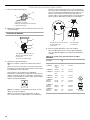
Burner Models for Kit W10676662
Burner locations
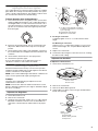
6. Remove all burner caps and burner bases (see the User
Guide for burner reference).
To remove the burner base for the Dual Flame and Dual Tier
Ultra Torch burners use a Torx
®
T10 driver to remove the screw.
7. To Convert Standard Burner:
■ Use 7.0 mm wrench to loosen and remove the orifice
spud (A).
■ Set gas orifice spud aside.
■ Replace with correct LP gas orifice spud. See LP gas
orifice spud charts.
8. To Convert Dual Tier Ultra and Dual Flame Burners:
■ Use 7.0 mm wrench to loosen and remove the inner
orifice spud (A) and the outer orifice spud (B).
■ Set gas orifice spuds aside.
■ Replace with correct LP gas orifice spuds. See the LP gas
orifice spud charts.
Model No. Left
Front
Left
Rear
Center
Inner
Center
Outer
Right
Rear
Right
Front
Inner
Right
Front
Outer
KCGS550E
89
Black
66
White
45
Blue
97
Brown
70
Green
89
Black
N/A
KCGS556E
89
Black
66
white
45
Blue
101
Yellow
70
Green
89
Black
N/A
KCGS950ES
89
Black
66
White
45
Blue
97
Brown
70
Green
40
Pink
80
Pink
KCGS956ES
97
Orange
66
White
45
Blue
105
Red
70
Green
40
Pink
80
Pink
A. Left front
B. Left rear
C. Center
D. Right rear
E. Right front
Dual Tier Ultra Burner
A. Inner burner cap
B. Outer burner cap
C. Gas tube opening
D. Burner base
Standard and Dual Flame
A. Burner cap
B. Igniter electrode
C. Burner base
D. Gas tube opening
B
D
C
E
A
D
A
B
C
A
B
C
D
Torch Burner
A. Inner burner cap
B. Inner burner base
C. Outer burner base
D. Burner support
E. Gas tube opening
A. Orifice spud
Dual Tier Ultra Burner
A. Inner orifice spud
B. Outer orifice spud
Dual Flame Burners
A. Inner orifice spud
B. Outer orifice spud
E
D
A
B
C
A
A
B
A
B

6
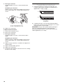
9. To Convert Torch Bur ner
■
Remove the spring that is shown in the following
illustration (C).
■ Use 7.0 mm wrench to loosen and remove the inner
orifice spud (A) and the outer orifice spud (B).
■ Set gas orifice spuds aside.
■ Replace with correct LP gas orifice spud. See the LP gas
orifice spud charts.
■ Return the spring to its original location.
IMPORTANT: Place Natural gas orifice spuds in plastic parts
bag for future use and keep with package containing
literature.
10. Replace sheet of insulation.
11. Replace burner bases and burner caps.
The igniter electrode is ceramic and could break during
conversion. Be sure that the electrode comes through the
hole in the burner smoothly while you are replacing the burner
base.
12. Open shutoff valve in the gas supply line. The valve is open
when the handle is parallel to the gas pipe.
13. Plug in cooktop or reconnect power.
REMEMBER: Once you have completed converting all of the
cooktop burners, test the cooktop for leaks by brushing on
an approved noncorrosive leak-detection solution. If bubbles
appear, a leak is indicated. Correct any leaks found.
14. To adjust single and dual valves, see the “Flame Height
Adjustment” section.
Convert from LP Gas to Natural Gas
1. Turn manual shutoff valve to the closed position.
2. Unplug cooktop or disconnect power.
To Convert Gas Pressure Regulator
3. Determine the type of regulator you have:
Style 1: The cap has a slot and “LP” printed on it.
Remove access cap by using a flat-blade screwdriver or coin,
turning the access cap counterclockwise.
The gas pressure regulator has 2 settings that are stamped
on either side of the cap. Turn the cap and reinstall into
regulator with the stamp “NAT” visible from the outside of the
regulator.
Style 2: The cap does not have a slot and requires a wrench
to be removed.
Remove the access cap by using a wrench, turning the
access cap counterclockwise.
A. Inner orifice spud
B. Outer orifice spud
C. Spring
A. Burner cap
B. Electrode
C. Burner base
A
B
C
B
C
A
A. To cooktop
B. Shutoff valve (closed position)
C.Gas supply line
A. Access cap
B. Rear of cooktop
C. Gas pressure regulator
D. Gas flow
A
B
C
A
B
C
D
NAT

7
Remove spring retainer from the cap by pushing against the
flat side of the spring retainer. Look at the spring retainer to
locate the “NAT” or “LP” position. Turn over the spring
retainer so the “NAT” is showing on the bottom. Snap the
spring retainer back into the cap. Reinstall the cap onto the
regulator.
4. If the burner grates are installed, remove them.
Use the following charts to match the correct gas orifice spud
with the burner location and model being converted.
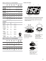
Natural Gas Orifice Spud Chart for Kit W10676661
Burner Models for Kit W10676661
Natural Gas Orifice Spud Chart for Kit W10676662
Burner Models for Kit W10676662
Burner locations
5. Remove all burner caps and burner bases (see the User
Guide for burner reference).
A. Access cap
B. Gasket
C. Gas pressure regulator
D. NAT position
E. LP position
Burner
Rating
Color Stamp (A) Size
5,000 BTU
Green
95 0.95 mm
A. Size stamp
9,100 BTU White or
no color
130 1.30 mm
10,000 BTU Orange 135 1.35 mm
12,00 BTU Red or
Blue
150 1.50 mm
15,000 BTU Yellow 175 1.75 mm
18,00 BTU Pink 189 1.89 mm
17,000 BTU
Inner
Outer
Red
Red
175
57
1.75 mm
0.57 mm
18,00 BTU
Inner
Outer
Brown
Brown
180
57
1.80 mm
0.57 mm
19,000 BTU
Inner
Outer
White
White
185
57
1.85 mm
0.57 mm
Model No. Left
Front
Left
Rear
Center
Inner
Center
Outer
Right
Rear
Right
Front
Inner
Right
Front
Outer
WCG51US0D
MGC7430D
ICS500DS00
95
Green
175
Yellow
N/A N/A 150
Red
130
White
130
White
WCG75US0D
MGC9530D
95
Green
189
Pink
N/A N/A 150
Red
130
White
130
White
WCG97US09
KCGS350E
ICS655DS00
130
No
color
135
Orange
175
Red
175
Red
95
Green
130
No
color
130
No
color
WCG51US6D
MGC7536D
130
White
130
White
175
Yellow
175
Yellow
95
Green
150
Red
150
Red
WCG97US6D
MGC9536D
130
No
color
130
No
color
180
Brown
57
Brown
95
Green
150
Blue
150
Blue
KCGS356E
130
No
color
130
No
color
185
White
57
White
95
Green
150
Blue
150
Blue
A
B
CDE
A
Burner
Rating
Color Stamp (A) Size
6,000 BTU Red 105 1.05 mm
A. Size stamp
7,000 BTU Black 115 1.15 mm
10,000 BTU White 140 1.40 mm
12,00 BTU Brown 150 1.50 mm
17,000 BTU
Inner
Other
Blue
Green
91
160
0.91 mm
1.60 mm
18,000
Inner
Outer
Blue
Blue
91
165
0.91 mm
1.65 mm
20,000 BTU
Inner
Outer
Blue
Light Blue
91
180
0.91 mm
1.80 mm
10,000 BTU
Inner
Outer
Pink
Pink
66
123
0.66 mm
1.23 mm
Model No. Left
Front
Left
Rear
Center
Inner
Center
Outer
Right
Rear
Right
Front
Inner
Right
Front
Outer
KCGS550E
140
White
105
Red
91
Blue
160
Green
115
Black
140
White
N/A
KCGS556E
140
White
105
Red
91
Blue
180
Light
Blue
115
Black
140
white
N/A
KCGS950ES
140
White
105
Red
91
Blue
160
Green
115
Black
66
Pink
123
Pink
KCGS956ES
150
Brown
105
Red
91
Blue
180
Light
Blue
115
Black
66
Pink
123
Pink
A. Left front
B. Left rear
C. Center
D. Right rear
E. Right front
A
B
D
C
E
A

8
To remove the burner base for the Dual Flame and Dual Tier
Ultra Torch burners use a Torx
®
T10 driver to remove the
screw.
6. To Convert Standard Burner:
■ Use 7.0 mm wrench to loosen and remove the orifice
spud (A).
■ Set gas orifice spud aside.
■ Replace with correct Natural gas orifice spud. See Natural
gas orifice spud charts.
7. To Convert Dual Tier Ultra and Dual Flame Burners:
■ Use 7.0 mm wrench to loosen and remove the inner
orifice spud (A) and the outer orifice spud (B).
■ Set gas orifice spuds aside.
■ Replace with correct Natural gas orifice spuds. See the
Natural gas orifice spud charts.
.
8. To Conver t Torch Bur ner
■
Remove the spring that is shown in the following
illustration (C).
■ Use 7.0 mm wrench to loosen and remove the inner
orifice spud (A) and the outer orifice spud (B).
■ Set gas orifice spuds aside.
■ Replace with correct Natural gas orifice spud. See the
Natural gas orifice spud charts.
■ Return the spring to its original location.
IMPORTANT: Place Natural gas orifice spuds in plastic parts
bag for future use and keep with package containing
literature.
9. Replace sheet of insulation.
10. Replace burner bases and burner caps.
The igniter electrode is ceramic and could break during
conversion. Be sure that the electrode comes through the hole
in the burner smoothly while you are replacing the burner base.
11. Open shutoff valve in the gas supply line. The valve is open
when the handle is parallel to the gas pipe.
12. Plug in cooktop or reconnect power.
REMEMBER: Once you have completed converting all of the
cooktop burners, test the cooktop for leaks by brushing on
an approved noncorrosive leak-detection solution. If bubbles
appear, a leak is indicated. Correct any leaks found.
13. To adjust single and dual valves, see the “Flame Height
Adjustment” section.
Dual Tier Ultra Burner
A. Inner burner cap
B. Outer burner cap
C. Gas tube opening
D. Burner base
Standard and Dual Flame
A. Burner cap
B. Igniter electrode
C. Burner base
D. Gas tube opening
Torch Burner
A. Inner burner cap
B. Inner burner base
C. Outer burner base
D. Burner support
E. Gas tube opening
A. Orifice spud
D
A
B
C
A
B
C
D
E
D
A
B
C
A
Dual Tier Ultra Burner
A. Inner orifice spud
B. Outer orifice spud
Dual Flame Burners
A. Inner orifice spud
B. Outer orifice spud
A. Inner orifice spud
B. Outer orifice spud
C. Spring
A. Burner cap
B. Electrode
C. Burner base
A
B
A
B
A
B
C
B
C
A

9
Lighting the Electronic Igniters
The cooktop burners use electronic igniters in place of standing
pilots. When the cooktop control knob is pushed in, the system
creates a spark to light the burner. This sparking continues until
the control knob is turned to the desired setting.
To Check Operation of the Cooktop Burners:
1. Push in and turn knobs to the ignition position (see the User
Guide for additional information). The cooktop burner flame
should light within 4 seconds. The first time a burner is lit, it
may take longer than 4 seconds to light because of air in the
gas line. Do not leave the knob in the ignition position after
the burner lights.
2. If burners do not light properly, turn the control knob to the
Off position. Make sure the burner caps are in the proper
position.
3. Check that the power supply cord is plugged in. Check that
the circuit breaker has not tripped or the household fuse has
not blown.
4. Check that the shutoff valve is in the open position.
5. Check burner operation again.
If one or all of the burners do not light at this point, see
“Assistance or Service” section in the User Guide.
Flame Height Adjustment
Each burner flame has been factory set to the lowest position
available to provide reliable and constant reignition of the burner.
However, each burner can be adjusted.
NOTE: If your model number begins with KGCS5 or KGCS9, call
service, as this operation will require opening the unit.
To Adjust:
The flame can be adjusted using the adjustment screws
underneath the control knob.
NOTE: Check the Use and Care Guide for information on each
burner to determine whether they are single or dual flame. Adjust
the valves accordingly.
Adjustment for Single Valve
1. Set the burner flame to LO.
2. Remove the control knob.
3. Hold knob stem with a pair of pliers. Use a ³⁄₃₂" (#0 [2.0 mm])
flat-blade screwdriver to turn the screw located within the
shaft of the control knob stem until the flame is the proper
size.
4. For LP gas conversion:
Completely tighten screw “C” to set the minimum flame
height.
For Natural gas conversion:
Tighten screw “C” to reduce flame height. Loosen screw to
increase flame height. See “Complete Burner Adjustment”
section.
5. Replace the control knob.
6. Test the flame by turning the control from LO to HI, checking
the flame at each setting.
Adjustment for Dual Valve
To Adjust Inner Crown Flame:
1. Set the inner crown flame to LO.
2. Remove the control knob.
3. Remove the black rubber grommet.
4. Using needle-nose pliers, remove the gray shield inside the
burner valve opening.
A.
³⁄₃₂
" (#0 [2.0 mm]) flat-blade screwdriver
(screwdriver shaft must be a minimum of
2" [5.1 cm] long)
B. Control knob stem opening
C. Adjustment screw location
A. Inner crown
B. Outer crown
A. Control knob
B. Black rubber grommet
C. Gray shield
B
C
A
A
B
M
e
d
A
B
C

10
5. For LP gas conversion:
Completely tighten screw “A” to set the minimum flame
height.
For Natural gas conversion:
Tighten screw “A” to reduce flame height. Loosen screw to
increase flame height. See “Complete Burner Adjustment”
section.
6. Replace the control knob.
To Adjust Outer Crown Flame:
1. Set the outer crown flame to LO.
2. Remove the control knob.
3. For LP gas conversion:
Completely tighten screw “B” to set the minimum flame
height.
For Natural gas conversion:
Tighten screw “B” to reduce flame height. Loosen screw to
increase flame height. See “Complete Burner Adjustment”
section.
4. Replace the gray shield. Use a screwdriver to help push the
shield into place.
5. Replace the black rubber grommet.
6. Replace the control knob.
7. Test the flame by turning the control from LO to HI, checking
the flame at each setting.
Complete Burner Adjustment
1. Check burner flame(s) for a proper size and shape. The
cooktop low burner flame should be a steady blue flame
approximately ¹⁄₄" (0.64 cm) high.
2. Completely fill out the conversion label and attach label to
bottom of the cooktop next to the rating tag. Do not cover the
rating tag with the conversion label.
IMPORTANT: Place gas orifice spuds in plastic parts bag for
future use and keep with package containing literature.
Read “Sealed Surface Burners” section in the Use and Care
Guide supplied with your cooktop.
A. Inner crown adjustment screw
B. Outer crown adjustment screw
B
A
A. Low flame
B. High flame
A
B
Page is loading ...
Page is loading ...
Page is loading ...
Page is loading ...
Page is loading ...
Page is loading ...
Page is loading ...
Page is loading ...
Page is loading ...
Page is loading ...
-
 1
1
-
 2
2
-
 3
3
-
 4
4
-
 5
5
-
 6
6
-
 7
7
-
 8
8
-
 9
9
-
 10
10
-
 11
11
-
 12
12
-
 13
13
-
 14
14
-
 15
15
-
 16
16
-
 17
17
-
 18
18
-
 19
19
-
 20
20


Ask a question and I''ll find the answer in the document
Finding information in a document is now easier with AI
in other languages
Related papers
-
Whirlpool 4 Stainless Steel Surface 24-Inch Gas Cooktop Operating instructions
-
KitchenAid YKDSS907SS00 Installation guide
-
-
-
-
-
KitchenAid KGCU482VSS User manual
-
-
KitchenAid KFGD500ESS00 Installation guide
-
Other documents
-
JennAir JGC3530GS Operating instructions
-
JennAir JGC3115GS Operating instructions
-
Whirlpool WFG510S0HW0 Installation guide
-
Estate TGS325VB Installation Instructions Manual
-
-
Maytag TGS325VQ0 Installation guide
-
Inglis IGS326RD1 Installation guide
-
Whirlpool SF462LXSQ0 Installation guide
-
-
Whirlpool W10658550A User manual