Versitron FDVTR1AA5A-AE Owner's manual
- Category
- Video switches
- Type
- Owner's manual
This manual is also suitable for

FDVx1AAx
VersiVision
FDVT1AAxA-AE / FDVR1AAxA-AE
1-CHANNEL DIGITALLY ENCODED VIDEO
1-CHANNEL BI-DIRECTIONAL DATA
1-CHANNEL BI-DIRECTIONAL CONTACT CLOSURE
1-CHANNEL BI-DIRECTIONAL AUDIO
AND
1-CHANNEL 10/100BASE ETHERNET
MULTIPLEXER
USER’S MANUAL
Revision D
© April 2013
VERSITRON, Inc.
83 Albe Drive / Suite C
Newark, DE 19702
www.versitron.com

www.versitron.com FDVx1AAx
PROPRIETARY DATA
All data in this manual is proprietary and may not be disclosed,
used or duplicated, for procurement or manufacturing purposes,
without prior written permission by VERSITRON.
WARRANTY
All VERSITRON products are covered by a Lifetime Warranty against defects in materials
and workmanship. This coverage is applicable to the original purchaser and is not transferable.
We repair, or at our option, replace parts/products that, during normal usage and operation, are
proven to be defective during the time you own the products, provided that said products and parts
are still manufactured and/or available. Such repair/replacement is subsequent to receipt of your
product at our facility and our diagnostic evaluation and review of the unit.
This warranty does not cover damage to products caused by misuse, mishandling, power surges,
accident, improper installation, neglect, alteration, improper maintenance, or other causes which
are not normal and customary applications of the products and for which they were not intended.
No other warranty is expressed or implied, and VERSITRON is not liable for direct, indirect,
incidental or consequential damages or losses.
In the unlikely event a warranty issue should arise, simply contact us at 302-894-0699 or
1-800-537-2296 or via email at fibe[email protected] to obtain a Return Material Authorization
(RMA) number, along with instructions for returning your product.
Note: This warranty is effective for commercial products as of January 1, 2001 and for GSA
products as of July 1, 2006.

www.versitron.com FDVx1AAx
Table of Contents
General Information ……………………………………………………………….. 3
Introduction ……………………………………………………………………. 3
Technical Specifications ………………………………………………………. 3
Installation Instructions …………………………………………………………… 6
Installation Procedure ……………………………………………….………… 6
Indicator LEDs ………………………………………………………………… 7
System Terminal Block Connections …………………………………………. 7
Troubleshooting …………………………………………………………………… 11

www.versitron.com FDVx1AAx
GENERAL INFORMATION
Introduction:
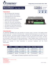
The VERSITRON VersiVision FDVT1AAxA-AE and FDVR1AAxA-AE Series video, data and
audio transmitter and receiver support simultaneous transmission of one channel of 8-bit digitally
encoded video, one channel of bi-directional data and one-channel of bi-directional audio over one
multi-mode or single-mode optical fiber. The modules are universally compatible with major
camera systems and support the RS-485 data protocol. Plug and Play design ensures ease of
installation and electronic and optical adjustments are never required.
Model Number
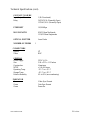
Technical Specifications:
VIDEO
Video Input 2.0 volt pk-pk (75 ohms)
Input/Output Channels 1
Bandwidth 5 Hz - 8 MHz
Bit Resolution 8-bit
Differential Gain < 2%
Differential Phase < 0.6°
Tilt < 1%
S/N Ratio 60dB (Weighed)
DATA
Data Interface RS-485 (RS-422, RS-232 Optional)
Data Channel 1-Channel Bi-Directional
Data Rate 100Kbps
Bit Error Rate 10
-9
AUDIO
Audio Impedance 600 Ohms
Input/Output Voltage 2.0Vp-p
Frequency Response 10Hz - 20Khz
Bit Resolution 24-Bit
S/N Ratio 95dB
Unit Type Model Number
1-channel Digitally Encoded Video + Bi-Directional Data & Audio Transmitter FDVT1AAxA-AE
1-channel Digitally Encoded Video + Bi-Directional Data & Audio Receiver FDVR1AAxA-AE

www.versitron.com FDVx1AAx
Technical Specifications (cont):
CONTACT CLOSURE
Input/Output Channels 1 (Bi-Directional)
Relay 24VDC/0.5A (Normally Open)
125VAC/0.1A (Normally Open)
ETHERNET 10/100Mbps
WAVELENGTH 850/1310nm Multimode
1310/1550nm Singlemode
OPTICAL EMITTER Laser Diode
NUMBER OF FIBERS 1
CONNECTORS
Optical ST
Video BNC
GENERAL
Power Supply 5VDC @ 2A
Size 5.98 x 5.12 x 1.13 Inches
Construction Aluminum
MTBF > 100,000 hours
Operating Temp -35° C to + 65° C
Storage Temp -45° C to + 85° C
Relative Humidity 0% to 95% (non-condensing)
INDICATOR
Green Video Sync Present
Green Data Sync Present
Green Power On

www.versitron.com FDVx1AAx
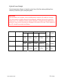
Optical Power Budget
Optical transmission distance is limited to optical loss of the fiber and any additional loss
caused by connectors, splices, and patch panels.
Transmitter Receiver Fiber Wavelength
Model Output Model Sensitivity
Optical
Power
Budget
Max
Distance
Singlemode 1310/1550nm FDVT
1AA5A-
AE
-5 dBm
FDVR
1AA5A-
AE
-26 dBm
21 dB
30 Km
Transmitter Receiver Fiber Wavelength
Model Output Model Sensitivity
Optical
Power
Budget
Max
Distance
Multimode 850/1310nm FDVT
1AA5A-
AE
-10 dBm
FDVR
1AA5A-
AE
-24 dBm
14 dB
3 Km
CAUTION!
The transmitter unit contains a laser-emitting diode located in the optical connector.
This device emits invisible infrared electromagnetic radiation that can be harmful to
human eyes. The radiation from this optical connector, if viewed closely without any
protection, may cause instantaneous damage to the retina of the eye. Direct viewing of
this LED should be avoided at all times.

www.versitron.com FDVx1AAx
INSTALLATION INSTRUCTIONS
Installation Procedure
The VERSITRON VersiVision FDVT1AAxA-AE and FDVR1AAxA-AE video transmission
systems series are preset for immediate use. There are indicator LEDs on the units for
monitoring the real-time status of video, data and power. The following instructions describe
the typical installation procedure and the function of the LED indicators located on each unit.
1. Connect the video source (camera) to the video input BNC connector on the transmitter
unit (FDVT1AAxA-AE) using coaxial cable.
2. Connect the video output BNC connector on the receiver unit (FDVR1AAxA-AE) to the
video monitor using coaxial cable.
3. Connect the fiber optic cable between the transmitter and receiver units.
4. Apply the power supply to both the transmitter and receiver units.
5. When the power is applied, the green POWER LED will light, indicating the presence of
operating power. The green VIDEO LED and DATA LED will give an indication as stated
on the following pages.
6. The system should now be operational.

www.versitron.com FDVx1AAx
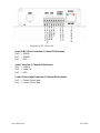
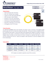
Indicator LEDs
The stand-alone units have integral LEDs that are used to monitor the state of the unit. There
are one video LED and one power LED on each unit. One, labeled as “PWR, lights when
operating power is present. Another LED under the BNC connector will illuminate when the
video input/output signals are detected. The other LEDs above the green terminals blink at the
rate of the operating data. As shown in the following diagram:
TRANSMITTER and RECEIVER:
Power: ON: (Green) Indicates that correct power has been applied
Transmitter:
Video: OFF: Indicates no video detected on input BNC connector
(No Video present on input BNC)
ON: (Green) Indicates video detected on input BNC connector
(Video present on input BNC)
Data: OFF: Indicates no data detected on the transmit data cable
Blinking: (Green) Indicates data transmitted at the rate of the operation data.
Receiver:
Video: OFF: Indicates no video present on output BNC connector
(No Video present on output BNC)
ON: (Green) Indicates video detected on output BNC connector
(Video present on input BNC)
Data: OFF: Indicates no data detected on the receive data cable
Blinking: (Green) Indicates data received at the rate of the operation data.
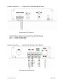
System Terminal Block Connections
The various input and output connections for the VERSITRON VersiVision
FDVT1AAxA-AE and FDVR1AAxA-AE
video transmission systems series are as follows:
Video Input or Output: BNC Connectors
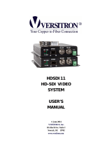
System Connection —— Camera Site (Transmitter Front Panel):

www.versitron.com FDVx1AAx
*Front panel of FDVT1AAxA-AE
Data RS-485 2-Wire Connection (1-Channel Bi-directional)
Pin 6——RS485A
Pin 7——RS485B
Pin 5——GND
Audio Connection (1-Channel Bi-directional)
Pin 9——Audio In
Pin 8——Audio Out
Pin 5——GND
Contact Closure Input Connection (1-Channel Bi-directional)
Pin 1——Contact Closure Input
Pin 2——Contact Closure Input

www.versitron.com FDVx1AAx
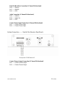
System Connection —— Camera Site (Transmitter Rear Panel):
*Rear panel of FDVT1AAxA-AE
Contact Closure Output Connection (1-Channel Bi-directional)
Pin 1——Contact Closure Output
Pin 2——Contact Closure Output
System Connection —— Control Site (Receiver Front Panel):
*Front panel of FDVR1AAxA-AE

www.versitron.com FDVx1AAx
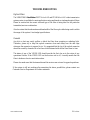
Data RS-485 2-Wire Connection (1-Channel Bi-directional)
Pin 6——RS485A
Pin 7——RS485B
Pin 5——GND
Audio Connection (1-Channel Bi-directional)
Pin 9——Audio In
Pin 8——Audio Out
Pin 5——GND
Contact Closure Input Connection (1-Channel Bi-directional)
Pin 1——Contact Closure Input
Pin 2——Contact Closure Input
System Connection —— Control Site (Receiver Rear Panel):
*Rear panel of FDVR1AAxA-AE
Contact Closure Output Connection (1-Channel Bi-directional)
Pin 1——Contact Closure Output
Pin 2——Contact Closure Output

www.versitron.com FDVx1AAx
TROUBLESHOOTING
Optical Fiber
The VERSITRON VersiVision FDVT1AAxA-AE and FDVR1AAxA-AE video transmission
systems series is available for most applications using multimode or singlemode optical fibers.
Please be certain that the correct size and type of the fiber is being used for the particular
transmitter/receiver combination.
Also be certain that the attenuation and bandwidth of the fiber optic cable being used is within
the range of the system’s loss budget specifications.
General
Any dirt or dust may easily pollute or block the fiber from accepting or radiating light.
Therefore, please try to keep the optical connector clean and always use the dust caps
whenever the connector is exposed to air. It is suggested that the tip of the optical connecter
should be carefully cleaned with a lint-free cloth moistened with alcohol from time to time.
The status of any of the VIDEO LED should provide the first clue as to the origin of any
operational failure. If the VIDEO LED on the receiver unit is off, it usually means that the
fiber is broken or has too much attenuation.
Please also make sure that the transmitter and the receiver are not used in opposite positions.
If the system is still not working after examining the above possibilities, please contact our
Customer Service Department for further assistance
-
 1
1
-
 2
2
-
 3
3
-
 4
4
-
 5
5
-
 6
6
-
 7
7
-
 8
8
-
 9
9
-
 10
10
-
 11
11
-
 12
12


Versitron FDVTR1AA5A-AE Owner's manual
- Category
- Video switches
- Type
- Owner's manual
- This manual is also suitable for
Ask a question and I''ll find the answer in the document
Finding information in a document is now easier with AI
Related papers
-
 Versitron FDVTR1A03A Owner's manual
-
 Versitron FVMTR4AC5A-C0 Owner's manual
-
 Versitron FVMTR2A03A Owner's manual
-
 Versitron FVMTR2BB3A Technical Manual
-
 Versitron FVMTR2005A Technical Manual
-
 Versitron FVMTR2BB3A Technical Manual
-
Versitron HDCVITR2A05 User manual
-
 Versitron FVMTR2005A Technical Manual
-
-
 Versitron HDSDI11 Owner's manual


Other documents
-
Standard Horizon Modem FVR1000 User manual
-
ATC 277SM User manual
-
Radiant Communications VABX700S Series User manual
-
 Optical Systems Design OSD361 User manual
-
 oxic XFO1013TS User manual
-
CSI Fiberlink 7220 Series User manual
-
-
-
-

