Page is loading ...

Page / Página 1 05_25720_25721_25733_25734_0A
ShadeLogic
™
Sun Shade Sail
™
Assembly Instructions / Manuel d’instruction
Instruciones de Ensamblaje
DESCRIPTION / DESCRIPCIÓN MODEL / MODÈLE / MODELO Nº
12 ft. / 3,7m Sun Shade Sail
™
-Triangle / Triángulo - Sand
25720
16 ft. / 4,9m Sun Shade Sail
™
-Triangle / Triángulo - Sand
25721
12 ft. / 3,7m Sun Shade Sail
™
-Triangle / Triángulo - Sea
25733
16 ft. / 4,9m Sun Shade Sail
™
-Triangle / Triángulo - Sea
25734
Please read instructions COMPLETELY before assembly. This shelter MUST be securely anchored.
THIS IS A TEMPORARY STRUCTURE AND NOT RECOMMENDED AS A PERMANENT STRUCTURE.
Before you start: 2+ individual recommended for assembly, approximate time 1 hr.
150 Callender Road
Watertown, CT 06795
www.shelterlogic.com
1-800-524-9970
1-800-559-6175
Canada:
11/15/10
RECOMMENDED TOOLS / OUTILS RECOMMANDÉS / HERRAMIENTAS RECOMENDADAS:
Lire TOUTES les instructions avant de monter. Cet abri DOIT
être bien ancré.
CECI EST UNE STRUCTURE TEMPORAIRE, IL N'EST PAS
RECOMMANDÉ D'EN FAIRE UNE STRUCTURE PERMANENTE.
Avant de commencer: Il faut 2 personnes ou plus pour le montage
qui prend environ 1 heure.
Por favor lea las instrucciones COMPLETAMENTE antes de
ensamblar. Esta carpa DEBE de estar anclada de manera
asegurada.
ESTA ES UNA ESTRUCTURA TEMPORAL Y NO SE RECOMIENDA
COMO ESTRUCTURA PERMANENTE.
Antes de empezar: se recomiendan 2 o más personas para
ensamblar, el tiempo aproximado de ensamble son 1 hora.

Page / Página 2 05_25720_25721_25733_25734_0A
3,7m / 12 ft. or 4,9m / 16 ft. ShadeLogic
TM
Sun Shade Sail
TM
Models / Modèles / Modelos N
o
25720, 25721, 25733 or 25734
3
3
3
6
6
6
3
1
Turnbuckle / Ridoir / Torniquete
Drop-in Anchor / Cheville / Caída de Ancla
Eye Bolt / Boulon à Oeil / Perno de Ojo
Washer / Joint / Junta de Culata
Hex Nut / Écrous / Nueces
Wire-Rope Clip / Serre Câble / Gancho de Cable
3m / 10 ft. Nylon Rope / Corde en Nylon / Cuerda de Nylon
Sun Shade Sail
™
- Triangle / Triángulo
Description of Parts / Description des Pièces / Descripción of Piezas:
Quantity /
Quantité
Cantidad
:
PROPER ANCHORING OF THE PRODUCT IS THE RESPONSIBILITY OF THE CONSUMER.
ShelterLogic
®
, LLC
is not responsible for damage to the unit or the contents from acts of nature. Any structure that is not installed
securely has the potential to y away causing damage, and is not covered under the warranty. Periodically check the anchors to ensure
stability. NOTE: Sun Shade Sails can be quickly removed and stored prior to severe weather conditions. If strong winds or severe
weather is forecasted, removal of the shade sail is recommended.
Covered by U.S. Patents and patents pending: 6,871,614; 6,994,099; 7,296,584; D 430,306; D 415,571; D 414,564; D 409,310; D 415,572
CARE AND CLEANING: To ensure best performance, always maintain a taut shade sail. Loose fabric can accelerate
deterioration. Use extreme caution and immediately remove any accumulated debris from the structure. DO NOT use hard-edged
tools or instruments. Shade sail is easily cleaned with mild soap and water, using a sponge or soft brush, letting it soak for 10 minutes.
Rinse thoroughly with water. DO NOT MACHINE WASH.
ATTENTION: This Sun Shade Sail is manufactured with quality materials and provides UV protection from the sun. Please anchor
this ShelterLogic
®
, LLC structure properly. Please read and understand the installation details and warnings prior to beginning
installation. If you have any questions, call the customer service number listed below.
DANGER: Choose the location carefully. Keep away from electrical wires. Check for overhead
utility lines, tree branches or other structures. DO NOT hang objects from the sail or support cables.
CAUTION: Use CAUTION when setting up the shade sail. Always use safety goggles during
installation. Ensure all mounting points are structurally sound and all hardware is secured tightly during
installation. Inspect regularly. Avoid exposure to aggressive chemicals (e.g. chlorine), as it may result
in premature breakdown of the fabric. Keep re and open ames away from the sail.
REPLACEMENT PARTS, ASSEMBLY, SPECIAL ORDERS: Genuine ShelterLogic
®
, LLC replacement parts and
accessories are available from the factory, including anchoring kits and fabrics. All items are shipped factory direct to your door.
QUESTIONS - CLAIMS - SPECIAL ORDERS? CALL OUR CUSTOMER SERVICE HOTLINE:
U.S. CUSTOMER SERVICE: 1-800-524-9970 INTERNATIONAL CUSTOMER SERVICE: 001-860-945-6442 CANADA CUSTOMER SERVICE: 1-800-559-6175
HOURS OF OPERATION: MON-FRI 8:30AM-8:00PM EST, SAT-SUN 8:30AM-5:00PM EST.
WARRANTY: This product carries a full limited warranty against defects in workmanship. ShelterLogic
®
, LLC warrants to the
Original Purchaser that if properly used and installed, the product and all associated parts, are free from manufacturer’s defects for a
period of:
Warranty period is determined by date of shipment from ShelterLogic
®
, LLC for factory direct purchases or date of purchase from an authorized
reseller, (please save a copy of your purchase receipt). If this product or any associated parts are found to be defective or missing at the time of receipt,
ShelterLogic
®
, LLC will repair or replace, at it’s option, the defective parts at no charge to the original purchaser. Replacement parts or repaired
parts shall be covered for the remainder of the Original Limited Warranty Period. All shipping costs will be the responsibility of the customer. Parts and
replacements will be sent C.O.D. You must save the original packaging materials for shipment back. If you purchased from a local dealer, all claims must
have a copy of original receipt. After purchase, please ll out and return warranty card for product registration. Please see warranty card for more details.
1 YEAR FOR SHADE SAIL FABRIC
11910

05_25720_25721_25733_25734_0APage 4
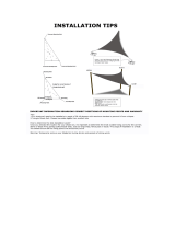
2. DETERMINING ANCHORING / FIXING POINTS
Once the location is chosen, it is important to determine the most suitable xing points for the sail's corners
(e.g. a pergola, sundeck, large tree, fence post or fascia).
This stage of installation is critical! Ensure all xing points are structurally sound and if uncertain, obtain
independent advice from a technician or engineer. A xing height of at least 8 ft. is recommended.
Lay out the sail in a large open space to determine suitable xing points. Allow a minimum of an ad-
ditional 10% of the sail's length between each xing point and the sail's corner ring for the tensioning device
(turnbuckle). See Diagram A.
If you have a 12-ft. Sail: 10% = 14.5 inches If you have a 16-ft. Sail: 10% = 19.25 inches
Attaching to a fascia: The use of a fascia support is strongly recommended. A fascia support connects the
overhangs of rafters or trusses and is available from your local hardware store. See Diagram B.
Attaching to trees: Attach the sail to trees temporarily only. The recommended diameter of the tree should
be at least 10 inches.
Minimum 10%
of sail length
Fixing
Point
Minimum 10%
of sail length
Fixing
Points
Fascia
Sail
Rafter
or Truss
Fascia
Support
1. DETERMINE A SUITABLE LOCATION
It's very important that you consider the most suitable location for your sail. Take into account the following:
A. Size of the sail.
B. Strength of the existing structures intended to be anchoring points.
C. Possibility to insert xing posts.
D. Location of barbecues, sun direction, high wind areas, electrical / telephone cables, water pipes, etc.
Connect all points and pre-tension the sail by hand at rst. Complete the tension by using the turnbuckle.
Stop increasing the tension when the sail becomes rigid and little or no fold marks are visible. Do not over-
tighten the sail.
4. TENSION
The hardware enclosed is suitable for most common xing points. Additional hardware such as D-shackles,
pad-eyes, S-hooks, snap hooks, strap tensioners, etc. are available at your local hardware store. Attach the
hardware to the mounting points as required, facing towards the middle of the sail (see Diagram C). Secure
tightly. See Diagram D for a sample conguration.
3. ATTACHING THE SAIL
Dia. D
Dia. C
Dia. A
Dia. B
EyeBolt
Turnbuckle
Nylon Rope
Rope Clips
Corner
Ring
Shade
Sail

Página 6 05_25720_25721_25733_25734_0A
2. DETERMINACIÓN DE PUNTOS DEL ANCLAJE / DE LA FIJACIÓN
Una vez que se elige la localización, es importante determinar los puntos más convenientes de la jación para las esqui-
nas de la vela (p.ej. una pérgola, terraza al sol, árbol grande, poste de la cerca o una pared).
¡Esta etapa de la instalación es crítica! Asegúrese que todos los puntos de la jación sean de estructuras sanas y si
estan inciertos, obtengan consejo independiente de un técnico o de un ingeniero. Una altura de jación se recomienda
por lo menos de 8 pies.
Presente la vela en un espacio abierto grande para determinar puntos convenientes de la jación. Permita un
mínimo de un 10% adicional de longitud de la vela entre cada punto de la jación y el anillo de la esquina de la vela para
el dispositivo tensor (torniquete). Vea el Diagrama A.
Si usted tiene una Vela de 12 pies: 10% = 14.5 pulgadas Si usted tiene una Vela de 16 pies: 10% = 19.25 pulgadas
Atadura a una pared: El uso de un soporte de una pared se recomienda fuertemente. Un soporte de la pared conecta
las proyecciones de vigas o de bragueros y está disponible de su almacén local de ferretería. Vea el Diagrama B.
Atadura a los árboles: Atando la vela a los árboles temporalmente solamente. El diámetro recomendado del árbol debe
ser por lo menos 10 pulgadas.
Pared
Vela
Viga o
Braguero
Soporte
de Pared
1. DETERMINE UNA LOCALIZACIÓN CONVENIENTE
Es muy importante que usted considere la localización más conveniente para su vela. Considere lo siguiente:
A. Tamaño de la vela.
B. La fuerza de las estructuras existentes que se prepuso ser puntos de anclaje.
C. Posibilidad para insertar los postes de jación.
D. Localización de barbacoas, dirección del sol, áreas de vientos fuertes, cables eléctricos / de teléfono, tubería de agua, etc.
Conecte todos los puntos y pretensióne la vela a mano al principio. Termine la tensión usando el torniquete.
Pare el aumentar de la tensión cuando la vela llega a ser rígida y poco o nada de marcas del doblez son
visibles. No apriete la vela demasiado.
4. TENSIÓN
La ferretería incluida es conveniente para la mayoría de los puntos comunes de la jación. La ferretería adicional tal
como D-grillos, los cojín-ojos, los ganchos-S, los ganchos rápidos, los tensores de la correa, etc. están disponibles en su
almacén local de ferretería. Ate la ferretería a los puntos de montaje como sea necesario, revestimiento hacia el centro
de la vela (vea el Diagrama C). Asegure rmemente. Vea el Diagrama D para una conguración de ejemplo.
3. ATADURA DE LA VELA
Perno de Ojo
Torniquete
Cuerda de
Nylon
Gancho de
Cuerda
Anillo de
la esquina
Vela de
Sombra
Mínimo 10%
de longitud de
la vela
Puntos de
Fijación
Punto de
Fijación
Mínimo 10%
de longitud de
la vela
Dia. D
Dia. C
Dia. A
Dia. B
/