Page is loading ...

ROTRONIC AG, CH-8303 Bassersdorf
Tel. +41 44 838 11 44, www.rotronic.com
ROTRONIC Messgeräte GmbH, D-76275 Ettlingen
Tel. +49 7243 383 250, www.rotronic.de
ROTRONIC SARL, 56, F - 77183 Croissy Beaubourg
Tél. +33 1 60 95 07 10, www.rotronic.fr
ROTRONIC Italia srl, I- 20157 Milano
Tel. +39 2 39 00 71 90, www.rotronic.it
ROTRONIC Instruments (UK) Ltd, West Sussex RH10 9EE
Phone +44 1293 571000, www.rotronic.co.uk
ROTRONIC Instrument Corp, NY 11788, USA
Phone +1 631 427-3898, www.rotronic-usa.com
ROTRONIC Canada Inc.,Canada L8W 3P7
Phone + 1 416-848-7524, www.rotronic.ca
ROTRONIC Instruments Pte. Ltd., Singapore 159836
Phone +65 6376 2107, www.rotronic.sg
ROTRONIC Shanghai Rep. Office, Shanghai 200233, China
Phone +86 40 08162018, www.rotronic.cn
Menu Navigation
Button Menu Points
MENU / One menu level back
Increase value / Display line up
Decrease value / Display line down
Change value / Display selection to the left
Change value / Display selection to the right
ENTER
SHORT INSTRUCTION MANUAL
Clean Room Panel
CRP1 SeRieS
☞
A
CRP1 panel
Wall bracket
Remark: Please note that the humidity and temperature probes must be ordered
separately.
Mechanical Installation
Select an installation site where the humidity, temperature and pressure conditions are represen-
tative of the environment that is to be measured.
A
Congratulations on your new CRP1 clean
room panel. You have bought a state-of-
the-art device. Please read these short
instructions carefully before installing
the device.
General Description
The CRP1 is a clean room panel for monitoring and control of essential parameters in a clean
room. It measures relative humidity and temperature with high precision using a HygroClip2
probe from ROTRONIC. It also features two analog outputs, two optional relays and a RS-485
interface to enable communication with MODBUS RTU. These short instructions are limited to a
description of the main functions and installation of the device. The detailed instruction manual
can be found on the internet at: www.rotronic.com.
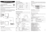
Dimensions / Connections
182
136
OK
24.5
53
107
153
1.5
40
15
136
124
182
170
Ø
3.5
• Constructasuitablerecessinyour
wall. You can use the dimensions given
below for this.
• Makesurethatallnecessaryelectric
cables have been passed through the
cable bushings in the wall bracket.
• Mountthewallbracketin thewall.
You can use the hardware provided
or a suitable glue for this.
• Connectallelectricconnectorstothe
CRP1.
• PushtheCRP1intothewallbracket.
The CRP1 is fastened mechanically by
its bolts.
• Tofastenthedevicepermanently,gluetheCRP1tothewallorwallbracketwithasuitableglue
or silicone.
Relative Humidity and Temperature Measurement
Relative humidity is extremely temperature-dependent. In order to measure it exactly, the probes
and sensors must be set exactly on the temperature level of the environments that are to be
measured.Theinstallationsitecanthereforehaveasignicantinuenceontheperformance
of the device.
Electrical Installation
Supply Voltage / Technology
Caution: Wrong supply voltages and excessive loads on the outputs can damage the
CRP1 clean room panel.
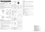
Terminal Assignment
Terminal Description
Power Supply
1 10...36 VDC
2 GND
Analog Outputs
3 Output 1
4 Output 2
RS-485
5 RXTX+ (MODBUS RTU)
6 RXTX- (MODBUS RTU)
HygroClip2 Connection
7 Probe power 5.0 V (green)
8 Probe GND (gray)
9 Probe RXD (red)
10 Probe TXD (blue)
Relays
11 Relay 2 +
12 Relay 2 –
13 Relay 1 +
14 Relay1−
Programming
The basic settings of the devices are made in the factory.
Service Interface / RS-485
Caution: Make sure that all settings have been made correctly before integrating and connecting
the CRP1 in the network.
Display
☞
Note: Unauthorized use of the
menu can be prevented by
disabling the setting “Display
Menu” (setting with HW4
software).
OK
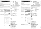
Menu Item Submenu Description Options
Device Settings
Units Units Metric / English
Backlight Backlight Key Press/On/Off
Contrast Contrast input 0…100
Trend Trend indicator On/Off
Interval Graphic interval 1…720
Disp.Mode Display mode Manual / Auto
Decimal Number of decimals to be shown 1…2
AudioAlarm Audible alarm signal ON / OFF
Device Information
Version Firmware version
Serial No. Serial number of the device
Address Device address
Type Device type
Name Device name
Probe Information
Version Firmware version
Serial No. Serial number of the probe
Address Probe address
Name Probe name
SensorTest Sensor test On/Off
Humidity Adjust
RefValue Input adjustment value
Acquired Number of adjustment points
<Acquire> Record adjustment point
<Delete> Delete adjustment point
<Adjust> Adjust
Temperature Adjust
RefValue Input adjustment value
<Adjust> Adjust
Alarm Settings
Set Alarm/Relay 1
Trigger by Switch parameters All parameters
High Limit Upper switching threshold Value
Low Limit Lower switching threshold Value
Delay1 Switch-off delay Value [s]
Set Alarm/Relay 2
Trigger by Switch parameters All parameters
High Limit Upper switching threshold Value
Low Limit Lower switching threshold Value
Delay2 Switch-off delay Value [s]
Communication
Baud Rate Value
Address Network address 00…63
Protocol Communication protocol Modbus RTU / RO-ASCII
Avoiding Sources of Error
Measuredvaluescanbecompromisedbythefollowinginuences:
Temperature errors:Throughinsufcientadaptationtime,coldouterwalls,heaters,direct
sunlight, etc.
Humidity errors: Through vapor, splashed water, dripping water or condensation on the sensor,
etc. This does not, however, impair reproducibility or long-term stability, even when the sensor is
exposed to high humidity or saturation with water vapor (condensation) for a prolonged period.
Soiling:Throughdustintheair.Theprobeltermustbecleanedorreplacedperiodically.
Scaling / Firmware Update
All device settings can be made with the help of the HW4 software and the AC3006 service cable.
Periodic Calibration of the Probe / Panel
The device and its probe are very stable and do not normally need to be changed or calibrated
after factory calibration. For maximum accuracy we recommend regular calibration of the device
and probe.
Caution: Make sure you do not touch the sensor when carrying out calibration or
adjustment work.
Technical Data
Device type Humidity / Temperature transmitter
Range of application -10…60 °C / 0…100 %RH, non-condensing
Measurement ranges 0…100 %RH, -100…200 °C (probe-dependent)
Accuracy humidity Probe-dependent
Accuracy temperature Probe-dependent
Startup time <15 s
Electrical connections Screw terminals at back
Power supply 10...36 VDC
Current consumption <500 mA
Inputs HygroClip2 input
Outputs 2 x 4…20 mA or 0…10 V (freely scalable), relay
Resolution 12 bit
Digital communication RS-485 (MODBUS RTU / HW4)
Permissible load >10 kΩ (voltage output)
Maximum load <500 Ω (current output)
HW4 compatibility V3.7.0 and later
Relay switching capacity <30 VDC at 2 A (optional)
<50 VAC at 0.5 A (optional)
Display 36 x 25 mm, monochrome LCD
Housing material Steel 1.4401 / Plastic
Dimensions 182 x 136 x 40 mm
IP protection Front IP65 / Rear IP54
Mounting position Wall mounting
Detailed documentation can be found on the internet at: www.rotronic.com
/


