DECATHLON-EP-ITEM CODE: BH53. INSTRUCTION MANUAL
20
3. Turn the airplane up side down. Place
your fingers on the masking tape and care-
fully lift the plane .
Accurately mark the balance point on the top
of the wing on both sides of the fuselage. The
balance point is located 60mm back from the
leading edge. This is the balance point at which
your model should balance for your first flights.
Later, you may wish to experiment by shifting
the balance up to 10mm forward or back to
change the flying characteristics. Moving the
balance forward may improve the smooth-
ness and arrow- like tracking, but it may then
require more speed for take off and make it
more difficult to slow down for landing. Moving
the balance aft makes the model more agile
with a lighter and snappier ”feel”. In any case,
please start at the location we recommend .
With the wing attached to the fuselage, all
parts of the model installed ( ready to fly), and
empty fuel tanks, hold the model at the
marked balance point with the stabilizer level.
Lift the model. If the tail drops when you
lift, the model is “tail heavy” and you must add
weigh* to the nose. If the nose drops, it is “nose
heavy” and you must add weight* to the tail to
balance.
*If possible, first attempt to balance the model
by changing the position of the receiver bat-
tery and receiver. If you are unable to obtain
good balance by doing so, then it will be nec-
essary to add weight to the nose or tail to
achieve the proper balance point.
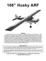
1) We highly recommend setting up a
plane using the control throws listed.
2) The control throws should be meas-
ured at the widest point of each control sur-
face.
3) Check to be sure the control surfaces
move in the correct directions.
CONTROL THROWS.
Ailerons : 8mm up 8mm down
Elevator : 16mm up 16mm down
Rudder : 20mm right 20mm left
Aileron Control
16
16
20
20
8
8
1) Completely charge your transmitter and
receiver batteries before your first day of fly-
ing.
2) Check every bolt and every glue joint in
your plane to ensure that everything is tight
and well bonded.
3) Double check the balance of the
airplane.
4) Check the control surface.
5) Check the receiver antenna . It should
be fully extended and not coiled up inside the
fuselage.
6) Properly balance the propeller.
PRE-FLIGHT CHECK.
We wish you many safe and enjoyable
flights with your DECA
THLON-EP.
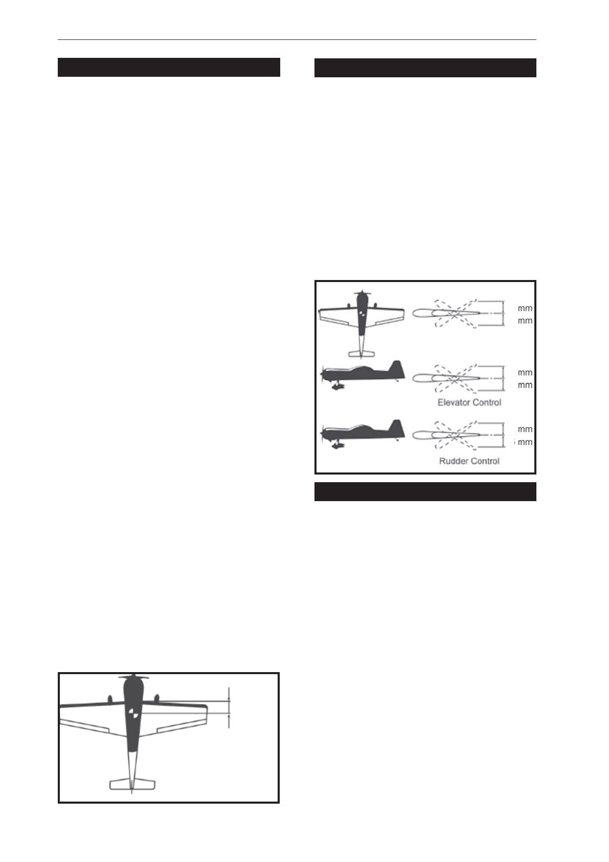
CG
60mm
1) It is critical that your airplane be bal-
anced correctly. Improper balance will cause
your plane to lose control and crash.
THE CENTER OF GRA VITY IS LOCA TED
60MM BACK FROM THE LEADING EDGE OF
THE WING.
2) Mount the wing to the fuselage. Using a
couple of pieces of masking tape, place them
on the top side of the wing 60 mm back from
the leading edge, at the fuselage sides.
BALANCING.