19
www.hearthrite.com
200128-01A
WARNING: You must oper-
ate this heater with the screen
in place. Make sure screen is
installed before running heater.
NOTICE: During initial operation
of new heater, burning logs will
give off a paper-burning smell.
Orange ame will also be pres-
ent. Open damper or window to
vent smell. This will only last a
few hours.
1. STOP! Read the safety information on
page 18.
2. Make sure equipment shutoff valve is fully
open.
3. Turn gas control knob clockwise to
the OFF position. Set the thermostat to the
lowest setting and turn ON/OFF switch to
the OFF position.
4. Wait ve (5) minutes to clear out any gas.
Then smell for gas around heater and
near the oor. If you smell gas, STOP!
Follow "B" in the safety information on
page 18. If you do not smell gas, go to
the next step.
5. Fro the OFF position, turn the gas con-
trol knob counterclockwise to the
PILOT position. Press in control knob for
ve (5) seconds.
Note: The rst time that the heater is
operated after connecting the gas supply,
the control knob should be pressed for
about thirty (30) seconds. This will allow
air to bleed from the gas system. If pilot
does not stay lit, refer to Troubleshooting,
pages 23 though 25. Also contact a quali-
ed service technician or gas supplier for
repairs. Until repairs are made, light pilot
with match.
• If control knob does not pop up when
released, contact a qualified service
technician or gas supplier for repairs.
6. With control knob pressed in, push
down and release ignitor button. This
will light pilot. The pilot is attached to
the rear of the burner. If needed, keep
pressing ignitor button until pilot lights.
Note: If pilot does not stay lit, refer to
Troubleshooting, pages 23 though 25.
Also contact a qualied service technician
or gas supplier for repairs. Until repairs
are made, light pilot with match. To light
pilot with match, see Manual Lighting
Procedure, page 20.
7. Keep control knob pressed in for 30
seconds after lighting pilot to prevent the
ame detector from shutting off the gas
whle the probe is warning up. After 30
seconds, release control knob.
Note: If pilot goes out, repeat steps 3
through 7. This heater has a safety inter-
lock system. Wait one (1) minute before
lighting pilot again.
8. Turn control knob counterclockwise
to the ON position. The main burner
should light. Set control knob to the de-
sired heating level.
Note: Please wait one minute after shut-
ting off heater to allow the control valve
to reset before starting again.
9. This valve is equpped with a HI/LO fea-
ture. Set replace input as desired.
10. If heater will not operate, follow the in-
structions To Turn Off Gas To Appliance,
page 20, and call your service technicial
or gas supplier.
11. Wait 30 seconds before readjusting the
heater when the control knob has been
turned down to a lower setting.
CAUTION: Do not try to ad-
just heating levels by using the
equipment shutoff valve.
LIGHTING INSTRUCTIONS
OPERATION
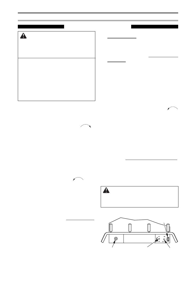
Ignitor
Control Knob
O (Remote)
I (Manual)
Switch
Flame Control
Figure 19 - Ignitor Button and Control
Knob Locations


