Page is loading ...

1
OPERATION
MANUAL
INTERPHASEINTERPHASE
TWINSCOPE™

2
To Our Customer:
Thank you for choosing the Interphase Twinscope Forward Scanning Sonar. Throughout the
development of this fine product, we have been primarily concerned with creating a unit that offers
the best possible value for your money. Selection of features, ease of use, superior performance
and outstanding reliability were the benchmarks upon which all important design decisions were
made. We feel proud of the Twinscope Forward Scanning Sonar and your satisfaction is very
important to us. To this end, we welcome any comments or suggestions that you might have in
regard to this equipment.
It is very important that you complete and return the WARRANTY REGISTRATION CARD
within 15 days of purchase so that your unit may be protected under the warranty.
Sincerely,
INTERPHASE TECHNOLOGIES, INC.
©2004 Interphase Technologies, Inc.
Interphase Twinscope™ is a trademark of Interphase Technologies, Inc.
Publication # = Twinscope 2.5
Interphase Part # = 25-1038-000

3
Table Of Contents
Important Notice 5
Principle of Operation 6
Display Unit Installation 8
Transducer Installation 12
Basic Operation 20
Getting Started 24
Vertical and Horizontal Scanning Modes 25
Vertical (Probe) Mode:
Set-Up View 28
Demo Program 28
Units of Measure 28
Language Selection 29
Transducer Level Adjustment 29
Forward View (Full Scan) 30
Plot (Track Plot) View 33
Chart View 35
Data View 39
Chart/Plot View 42
Chart/Scan View 44
Horizontal (Sea Scout) Mode:
Set-Up View 47
Alignment Adjustment 48
Forward View (Full Scan) 49
Plot (Track Plot) View 52
Chart View 54
Data View 58
Chart/Plot View 61
Chart/Scan View 63
NMEA 0183 Interface 66
Interpreting the Twinscope’s Forward Vertical (Probe) Display 67
Distance Forward 68
Noise and Sensitivity Adjustments 68
Transducer Sidelobe Effect 68
Interpreting the Twinscope’s Forward Horizontal (Sea Scout) Display 70
Noise and Sensitivity Adjustments 71
Reference Information 73
FAQ’s (Frequently Asked Questions) 76
Maintenance 78
Reset Unit & Calibration 79
Troubleshooting Guide 80
Interference Problems 81
Specifications 82
How To Obtain Service 85
Warranty 87

4
General Information
Thank you for your selection of the Interphase Twinscope
Forward Scanning Sonar. The Twinscope’s ruggedly built,
compact design makes it ideal for installation on nearly any
boat. It will display water depth, bottom conditions and
submerged objects such as fish, or objects in your path, on its
high resolution display. The Twinscope is available with
either two transom a single thru-hull or two thru-hull scanning
sonar depth transducers. In addition, an optional speed/
temperature transducer (either transom or thru-hull) is
available which will enable your Twinscope to display boat
speed, elapsed distance and surface water temperature. Refer
to the accessories part numbers printed in the Transducer
Installation section (Page 19) of this manual, then see your
dealer or call Interphase to order.
The Twinscope has an unprecedented number of advanced
features, in addition to the forward scanning capability, to
make your boating safer and your fishing more productive. Its
high resolution SuperTwist Liquid Crystal Display (LCD)
provides split screen views of 4X magnification zoom and
bottom lock, large digital display and speed and temperature
readings (with the speed/temperature transducer). You will
appreciate the very useful features of fish and depth alarms,
manual or automatic gain control, bottom hardness indicator
and fish symbol identification.
The Twinscope allows operation in your choice of nine
languages: English, French, Italian, Spanish, German, Danish,
Finnish, Swedish, or Greek. Power-off memory saves
language, depth range, gain and contrast settings, screen
advance speed and location in screen menu. Due to its unique
multi-tasking operation, the Twinscope provides instant full
screen updates when switching between modes (no data loss).
If you have your Twinscope interfaced with a Loran-C or GPS
unit, you can take advantage of the included track plot
displays. The Loran-C, DECCA, and GPS track plot displays
on the Twinscope give a whole new dimension, enabling you
to not only see the depths beneath and in front of your boat,
but also to see a graphic display of your boat’s position and
progress over time. The track plot display makes it easy to
find and return to the same fishing spot, or to troll back over
the same productive areas.
To ensure that you receive the maximum benefits available
from the outstanding features of the Interphase Twinscope,

5
please carefully follow the steps outlined in this manual. An
instructive demonstration simulator has been designed into the
Twinscope and we highly recommend that you spend some
time using the demo mode prior to actual use of the unit. We
also recommend that you read this entire manual before
attempting to either install or operate your Twinscope.
Warranty Information
Interphase provides a 5-Year limited warranty on the
Twinscope Forward Scanning Sonar. We strongly urge you to
read this warranty (reprinted at the back of this manual) and
closely follow its terms and conditions should your Twinscope
require repair. It is highly recommended that you save all
packing materials so that if you should need to send in the unit
for repair, it can be fully protected. If you wrap your display
unit in the original plastic bag and ship it in the box with
cardboard inserts, this will protect your unit from scratches
and shock during shipment.
Should you experience a problem with your Twinscope, first
refer to the Troubleshooting section (Page 80) of this manual.
Most common problems and their solutions are described here.
If problems persist, call Interphase Technical Service at
(831) 477-4944. We will be happy to try to assist you, and if
required, we will give you instructions on how to quickly get
your set repaired.
The enclosed warranty registration card must be completed
and returned to Interphase within 15 days of purchase so that
your unit may be protected under the warranty. Failure to
return the warranty card may cause unnecessary delays in
processing your unit for warranty repair.
WARNING
Navigation based solely on one method or
one instrument should never be practiced.
While the Twinscope can be quite useful in
showing underwater structure and changing
bottom conditions both below and in front of
your vessel, there are many situations and
conditions which can cause erroneous or
distorted readings.
In addition, there are many situations that can
cause “blind spots” in the Twinscope’s field
of view including the presence of
temperature inversion layers (thermoclines),
water turbulence, and high concentrations of
suspended particles in the water.
While the Twinscope can be considered as a
useful aid to navigation, it should never be
the only means of navigation.
IMPORTANT NOTICE
Since the Twinscope’s Forward Looking
technology is revolutionary, there is a strong
possibility that we will develop many new
and exciting features in the future. We
would like to make sure we can send you
information about these new features and
enhancements.
Please fill out and return the Warranty
Registration Card immediately. This is our
only method to keep in contact with you and
we may want to advise you of future
enhancements to your Twinscope.
If future changes or improvements are made,
software upgrades wil be available for a
nominal charge.

6
Principle of Operation
The Twinscope Forward Scanning Sonar uses a proprietary
phased array acoustic technology first developed for marine
use by Interphase Technologies. Known as “phased array
ultrasound technology”, its capabilities have been proven in
the medical industry for many years. The amazing video
images provided by medical ultrasound equipment are familiar
to most people and clearly demonstrate the technology’s
ability to show highly defined images in a "real time" or "live
action" mode. Interphase has taken this same technology and
modified it for use in the marine market.
Present day fish finders/ depth sounders all work on a principle
developed during W.W. II, called SONAR, where acoustic
pulses are used to detect the presence and range or distance to
an underwater object. During the 1950’s, several devices
which used sonar principles were developed and marketed to
fishing and boating enthusiasts to detect the distance to the
bottom (depth) and to indicate the presence of any intervening
submerged objects - such as fish.
An acoustic array is a group of piezoelectric ceramic elements
that are precisely sized and spaced. Each element will send
and receive acoustic pulses, as when used in more
conventional single element depth sounders. However, when
all elements in the array are sending or receiving acoustic
energy at the same time, the entire array behaves like a single
larger element with one important difference: the ability of the
array to concentrate its acoustic energy in different directions,
depending on the different “phasing” of the signals applied or
received by each element. Depending on the signal phasing of
the array, acoustic beams can be directed in an almost
unlimited number of directions. For example, using a 16
element phased array transducer, the Twinscope is capable of
steering the acoustic beam in any of 90 different directions in
either the horizontal or vertical direction. Conventional fixed-
beam technology would require the use of 180 different
elements to duplicate this capability. The resulting transducer
would be much too large and costly to be of any practical use.
Since the acoustic beam in the phased array is steered
electronically, requiring no moving parts, it can be quickly and
reliably scanned and re-scanned over a large area. When
displayed, the changing information between subsequent scans
takes on an almost animated quality - for example, showing
movement of underwater targets such as fish or rapidly
changing bottom conditions.
Award Winning
Technology
For its pioneering work in developing
Phased Array Scanning Sonar,
Interphase Technologies won the
prestigious IMTEC INNOVATION
AWARD.
The Twinscope Forward Looking
Scanning Sonar is based on this same
award-winning technology.

7
In addition to its ability to electronically steer an acoustic
beam, the phased array has other advantages over fixed-beam
technologies, such as: allowing the user to adjust the
transducer beam width, to scan large areas limited only by the
physics of the speed of sound in water (5,000 feet/second), and
the ability to provide nearly real time or live action underwater
views.
When operating, the Twinscope converts a small amount of
electrical current from your battery into ultrasonic sound
pulses, which are then fed to the phased array transducer.
These acoustic pulses travel out from the transducer in a cone
shaped pattern, called the cone angle. When the sound pulse
strikes an underwater object, it is reflected back (echo return),
received by the transducer and converted back into small
electrical impulses. These impulses are amplified, then
displayed as an image on the LCD screen.
The strength of the echo, the depth of the object, and the angle
of the transducer’s beam all affect how the image appears on
the display. Other factors which affect the image include boat
speed relative to the movement, position of the underwater
target and the number of objects reflecting pulses back to the
Twinscope.
The Twinscope’s forward looking display is new and learning
to properly interpret scanning sonar takes both patience and
experience, but once mastered, the Twinscope can offer
tremendous operational advantages over conventional fixed-
beam depth sounders. It is also important to realize that while
the Twinscope shows the bottom in both the forward and the
conventional downlooking mode, the presentations are really
quite different. The forward scan shows a view as the beam
“sweeps” across an arc (just like a radar), while the
conventional downlooking view shows a history of repetitive
soundings packed tightly together.

8
Installation
Display Unit
The compact size of the Twinscope display unit allows
for easy installation in almost any vessel. To get
maximum performance and life from your unit, the
following guidelines should be considered when
selecting a mounting location:
1) Select a location where the unit is protected from
excessive temperatures. Heat is one of the worst
enemies of electronic components, and will accelerate
component aging, thereby reducing the trouble-free life
of your Twinscope.
2) Mount the display in a location where it will be
convenient to route the power cord and transducer cable.
Power connection
Connect the two-pin plug on the end of the power
supply cable to the power supply jack located at the rear
of the main display unit. Connect the red wire to the
positive terminal and the black wire to the negative
terminal of your boat’s 12 VDC battery.
To minimize electrical interference, carefully route the
power cable so that it does not run parallel or close to
the transducer cable, engine, refrigeration, bilge pump or
any other critical wiring.
IMPORTANT: The Twinscope’s 12 VDC power leads
should go directly to the boat’s battery, distribution
board, or breaker panel. Instability of the display may
result if the unit has to share leads with other electrical
systems aboard your boat.
Shelf/Table
Overhead
IN-DASH BRACKET INSTALLATION
Optional in-dash bracket available.
Interphase part # 17-0054-008

9
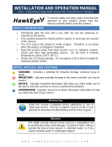
Transducer Connections
It is important that the two leads from the transducer or
transducers be connected to the correct connector on the
rear of the Twinscope . The label on the rear of the
Twinscope shows which transducer cable should be
connected to each of the two 9-pin connectors. If these
cables are reversed, the Twinscope will not scan
correctly.
The Twinscope can be purchased with either transom
mounted or thru-hull transducers.
The standard Twinscope single thru-hull transducer (T1-
I200-032) has two cables. Inside the transducer, one
cable connects to the array that does vertical scanning and
the other cable to the array that does the horizontal
scanning. These two cables are identified as either the
Probe (Vertical scanning) or Sea Scout (Horizontal
scanning) by a small label near the connector on each
cable. (see sketch at right)
The Twinscope can also use two seperate thru-hull
transducers - one for the Vertical scanning (Interphase
part number (T1-I200-026) and another for Horizontal
scanning (part number T1-I200-029). These transducers
can be identified by looking at the labels attached near the
connector on each cable.
For transom mount applications, the Twinscope uses two
seperate transducers, one for Vertical scanning (T1-0200-
025) and the other for Horizontal scanning (T1-0200-
028). These transducers can also be identified by
looking at the labels attached near the connector on each
cable.
The Transducer Installation Section, starting on page 12,
describes the procedures for properly installing the
Twinscope transducer(s) in the vessel.
Rear View of
Twinscope
Display
THRU-HULL
Vertical
Transducer Ca-
ble
12 VDC Power Cable
Horizontal Transducer Cable
CHECK LABEL ON TRANSDUCER CABLE
VERTICAL HORIZONTAL
TRANSOM
T1-0200-025 T1-0200-028
1 THRU HULL
PROBE/
VERTICAL
SEA SCOUT/
HORIZONTAL
2 THRU-HULLS
T1-I200-026 T1-I200-029

10
Note: The transom mount Probe (Vertical)
and Sea Scout (Horizontal) transducers are
almost identical in appearance. If the labels
are not readable, you can tell the difference by
looking at the mounting brackets. The Sea
Scout has a 1/4” hole drilled as shown in the
sketches below. Also, the Probe’s part number
(on the label) is T1-0200-025, and the Sea
Scout’s number is T1-0200-028.
PROBE
SEA SCOUT
Difference Between Probe and Scout
Transom Transducers

11
Wiring for Power and Transducer
Connectors
The correct pin-out wiring sequences for the power and
transducer connectors are shown at below. DO NOT
SHORTEN THE TRANSDUCER CABLES. If
transducer cables longer than the 30’ length supplied with
your unit is needed, please contact your Interphase
dealer. 30-foot scanning sonar transducer extension
cables are available. (P/N # 04-0014-008)
DANGER: Removal of any connector, disassembly of
transducer, shortening of any cable or use of any cable
other than that supplied by Interphase will void your
warranty. NO EXCEPTIONS.
Cable Connectors (view from front of female
plug)
Transducers:
1 White 1st element
2 Brown 2nd element
3 Orange 3rd element
4 Yellow 4th element
5 Green 5th element
6 Blue 6th element
7 Violet 7th element
8 Gray 8th element
9 Shield Ground/Return
NMEA & SPEED/TEMP Input
1 Speed Data
2 +5VDC
3 NMEA Data
4 N/C
5 NMEA Return
6 + Temp
7 - Temp
8 Shield/Ground
Power Connector
1 +12 vdc (red)
2 - Ground (black)
SINGLE THRU-HULL
TWO TRANSOM MOUNTS
TWO THRU-HULL'S
(T1-I200-032)
(T1-I200-026 - vertical)
(T1-I200-029 - horizontal)
(T1-0200-025 - vertical)
(T1-0200-028 - horizontal)
12 VDC
Battery
Power and Transducer
Connections
vertical transducer cable
speed/temp & NMEA
horizontal transducer cable
Transducer Configurations

12
Transducer Installation
The Twinscope comes standard with either a single or twin
thru-hull or with two transom mount forward scanning
transducers. An optional speed/temperature transducer is
also available which will allow the Twinscope to display
current boat speed, surface water temperature and elapsed
distance. The following section deals with the installation
of the scanning depth transducers only; installation
instructions for the optional speed/temperature transducer
are included with that accessory
The Twinscope’s uses two 8 element phased arrays (total of
16 elements). In the single thru-hull model all 16 elements
are enclosed in a single transducer. For transom mount
applications (or for the two thru-hull version) two
transducers are required, each containing an 8 element array.
One of the 8 element arrays is positioned to scan vertically
from straight ahead to directly below the boat, while the
other array is positioned to scan forward horizontally from
side to side. The Twinscope has an amazing amount of
capabilities, but it can not perform magic. It can not see
through objects such as your boat’s hull. Therefore, it is
important to position the transducer so that it has as clear a
view as possible of the water directly below and ahead of
your boat, as indicated at left.
The scanning transducer(s) must be positioned properly so
that it scans in the proper direction (i.e. from in front of the
boat to the bottom below). The sketch at left shows the
proper orientation for both the transom mount or the thru-
hull transducer(s). NOTE THAT ON THE TRANSOM
MOUNT TRANSDUCERS, THE ROUNDED SIDE
MUST POINT FORWARD, AND ON THE THRU-
HULL TRANSDUCER, THE MORE BLUNT AREA
MUST POINT FORWARD.
General Considerations
DO NOT CUT OR SPLICE YOUR PHASED ARRAY
TRANSDUCER CABLE OR REMOVE THE 9-PIN
CONNECTOR BECAUSE THE SYSTEM
PERFORMANCE MAY BE SERIOUSLY
DEGRADED. THIS ACTION WILL VOID YOUR
WARRANTY. NO EXCEPTIONS.
Forward Direction
Transom Mounted Transducer
Forward
Thru-Hull Transducer(s)
Scanning Directions.
Vertical scan Probe
mode shown above
and Horizontal Sea
Scout mode below
side view
top view

13
If you need a longer length cable than comes with the
transducer (30’), then purchase the optional 30’
extension cable, Interphase Part # 04-0014-008.
In addition to the above, the following considerations
should be observed:
1) Choose a location where there is the least amount
of acoustic noise, air bubbles or turbulence caused by
the boat’s movement. The transducer(s) should not be
located nearby or especially directly behind the
propeller.
2) Choose a location where the transducer(s) can be
mounted so that it will be level to the water’s surface
and will not be tilted to either side. Otherwise the
transducer(s) will not scan properly.
3) The transducer(s) must always remain
submerged, regardless of the speed of the boat and
should not be mounted where it could be damaged by
underwater obstacles or when loading on a trailer.
4) DO NOT locate the transducer(s) in the extreme
bow of the boat where it will be subject to intense
turbulence as the boat pounds through the water.
5) DO NOT locate the transducer(s) directly behind
any hull protrusion which will cause the water to be
turbulent when it reaches the transducer(s) or which
will obstruct the transducer’s forward looking view.
For displacement-hull power and sail boats, the thru-
hull installation is usually required.
DANGER: DO NOT allow any solvents, i.e. gasoline,
acetone, to come in contact with the transducer(s) or
display unit as this may dissolve the plastic material.
Transom Transducer Installation
The transom transducers are attached to the boat with
heavy-duty stainless kick-up brackets to provide
protection against impact at speeds of 25 - 30 MPH.
When the water force exceeds this setting, the
transducer automatically kicks up and becomes non-
operational.
30’ Extension Cable
9-pin
Male
9-pin
Female
Interphase Part #
04-0014-008
Transom Mount Bracket in Released
Position
Suggested materials required for installation:
♦ Variable speed electric drill with a chuck
capacity of 10mm (3/8”) or larger.
♦ Hole saw or spade bit 19 mm (7/8”) for
transom hole to route cable and
connector
♦ Chamfer bit or 6 mm (1/4”) drill bit
♦ Drill bit No. 28 or 4 mm (9/64”)
♦ Drill bit 3 mm (7/64”)
♦ Marine bedding/sealing compound
♦ Note: Make sure your tooling is sharp and
of the correct diameter before proceeding.
Note: Will not
work at speeds
above 30MPH

14
Transom Mounting Location
The main source of vessel acoustic noise is the propeller.
It is very important to position the transducers to
minimize noise pickup and provide as clear a view as
possible of the water ahead of the boat. Study the hull
shape of the vessel carefully to determine the best
transducer mounting location. To achieve optimal
operation the transducers should be mounted in a spot
which:
* Minimizes acoustic noise reception.
* Minimizes the chance that aerated water
will flow across the transducer’s frontal
nose area.
* Optimizes the transducers view of the area
ahead and directly below the boat. (See
diagram below, bottom left)
The transducers can be installed on either side of an
outboard or inboard/outboard engine, or between twin
outboards. For single engine installations, normally 18”
to 24” outboard of the propeller center line is acceptable
and the down stroke side of the propeller is preferred.
Choose a location where water flow is smoothest. For
dual engine installation, just off the center line is usually
acceptable.
Because the transducers rotate back and upwards when
the brackets kick up, they must be mounted in a location
where there is sufficient clearance and headroom to allow
the full kick-up.
Attaching the Transducer and Spray Shield
to the Bracket
Locate the stainless spray shield inside the transducer’s
stainless mounting ears. Make sure spray shield is
orientated as shown in sketch on following page.
Then, assemble the stainless kick-up bracket to the
transducers using the 4 screws, washers and lock nuts
provided. The bracket arms must be mounted outside the
stainless steel mounting ears of the transducer. Do not
fully tighten the lock nuts at this time.
Position the transducer so that it is perpendicular from
side to side and make sure the rounded shaped area is
pointed towards the front of the boat.
Mounting the Transducer to the Boat
After you have selected the optimum mounting location
and have assembled the mounting bracket to the
Boat’s Hull
Tramsom Mount Locations
18 - 24"
Cables
Twin Outboards
Transducer
Cable

15
transducer, mount the bracket onto the hull as shown
on the right.
Make sure to position the transducers so they are level
in both the fore and aft and side to side direction so
they will look straight down. Check the location of
your boat’s waterline and position the flat top surface
of the transducer so that it is parallel to the waterline as
shown below.
Note: If the transducers are not mounted so that the
fore and aft direction is parallel to the surface, then the
forward looking display may be distorted where flat
bottoms appear to be slanted upwards or downwards.
After mounting the transducer and actually using the
Twinscope on the water, you may need to readjust the
transducers' mounting for optimum performance.
Attach Transducers and Spray Shields to Brackets
Fasten with 4
screws &
nylock
washers as
shown
Side
View
Rear View
Spray Shield
Waterline
Transducer
must be
mounted
vertically
Rear
View
Side
view
Waterline
Flat area on top of
transducer must be
level with waterline
Mount Transducers So They Will Scan Properly

16
Thru-Hull Transducer Installation
The thru-hull transducer is the recommended choice for larger
boats with in-board engines. Thru-hull mounting is usually
required on larger power and sail craft in order to find a
mounting location free of forward looking hull obstructions.
The Twinscope must have a clear view of the water ahead as it
can not magically see through obstructions such as the vessel’s
hull. Please read the following carefully before starting the
thru-hull installation.
Normally, thru-hull installations are performed by a profes-
sional in a boat haul-out facility. We suggest you seek profes-
sional assistance before attempting to mount this transducer.
Selecting the Best Location
The best location to mount the thru-hull transducer will vary
with the type of boat. Try to find a location with the smallest
dead rise angle to make installation easiest.
a. On displacement hulls (sailboats, trawlers, etc.) locate the
transducer about 1/3 aft along the waterline. Generally this
provides the best compromise between obtaining aeration-free
water and minimizing propeller noise. The Twinscope’s
transducer can not see through aerated water and water near
the bow and near the keel can be quite aerated. Aeration of the
transducer can be minimized by keeping the transducer
mounted away from the keel and by not mounting too far
forward.
b. On sailboats, the transducer should be mounted where the
acoustic beam will not be shaded by the keel. Try to find an
accessible spot with a minimum dead rise angle.
c. On planing powerboat hulls, the transducer should be
mounted well aft and close to the keel to insure that the
transducer is in contact with the water at higher boat speeds.
On I/O’s, transducer mounting close to the
engine usually yields good results.
(Transducer in front of propeller.)
On inboards always mount the transducer
well ahead of the propeller(s). Turbulence
from props can seriously degrade perform-
ance. (Thru-hull installation is recommended.)
d. Mount the transducer on the side of the hull where the
propeller is moving downwards. The upward motion of the
propeller generates pressure waves and pushes bubbles up
against the hull.

17
DO NOT install a bronze transducer housing directly into
an aluminum or steel hull because electrolytic corrosion
will occur.
IMPORTANT:
1) Make sure the water flow across the thru-hull
transducer is bubble and turbulence free at all speeds if
good performance is to be achieved.
2) Make sure the transducer has an unobstructed view of
the water ahead and below the boat.
3) On displacement-hull power boats, the transducer
should be mounted relatively close to the center line of
the hull.
4) Mount the transducer in a place which has reasonable
access from inside the vessel since the transducer’s
bronze nut will require tightening from inside the hull.
Because the Twinscope scans a 12 degree beam from the
surface ahead to directly below the boat, it is important to
make sure that the transducer is installed so that it will
scan in a vertical direction and not off to either side. The
transducer must be mounted so that it’s bronze stem is as
perpendicular to the water line as possible. If necessary,
use a fairing block to properly position the transducer.
Use of a Thru-hull Fairing Block
Nearly all vessels have some dead rise angle at the
transducer mounting location. If the thru-hull transducer
were mounted directly to the hull, the sound beam would
be tilted off the vertical at the same angle as the dead-rise.
Most thru-hull installations will require a fairing block to
insure the transducer is mounted properly.
A fairing block is typically made of teak, mahogany
wood or plastic and should be placed between the
transducer and hull (both inside and outside) to insure
that the transducer’s mounting shaft is perpendicular to
the water’s surface. Make the fairing block as smooth as
possible, and not bigger than the transducer’s face, to
minimize possible turbulence.
After cutting the fairing block, trial fit the block to the
hull. It is very important that the flat top surface of the
transducer be parallel to the water. Because of the
equipment and skill required, we suggest that your
professional boatyard install the fairing block.
Suggested Thru-Hull
Transducer Locations
Fin Keel
Planing Hull
Displacement Hull -
Both Power and Sail

18
Installing the Thru-hull Transducer
1) Drill a 1/8” pilot hole from inside the hull to assure
access to tighten the housing nut and clearance for the
transducer cables. If there is any hull irregularity near the
selected mounting location, it may be desirable to drill from
the outside.
2) Use a 1 - 1/16” hole saw and drill the hole from the
outside of the hull. Sand or clean the area around the hole,
inside and outside to insure that the sealing compound will
adhere properly to the hull. Select a marine grade bedding/
caulking compound and use according to the instructions.
3) Remove the bronze hex nut from the housing and cables.
4) Uncoil the two transducer cables and thread it through
the hole into the inside of the hull.
DANGER: DO NOT apply tension to the transducer
cables as this may sever internal connections. Apply a 1/8”
thick layer of sealant on the upper flat surface of the bronze
housing and fairing block (if used).
5) From the outside of the hull, push the cables and
housing into the 1 - 1/16” hole. Twist the housing slightly
to squeeze out excess sealant. Carefully confirm that the
transducer is aligned so that the blunt rounded end (the
front) is pointed directly toward the front of the boat.
6) Install and tighten bronze hex nut (allow for swelling in
wooden hulls). Do not overtighten nut - especially if a
wooden fairing block is used as it will expand in water.
7) Remove excess sealant from the outside to assure
smooth water flow over the transducer.
DANGER: Wood hulls and fairing blocks will expand
after the boat is put back into the water, so it is important
that the transducer be only hand-tightened until the wood
fully expands. Otherwise the wood fairing block may
crack.
DANGER: Be sure to check for leaks when the boat is
placed in the water. Allow at least 24 hours after
installation for any leak to appear.
Hull
Hull
Waterline
Waterline
Keep parallel
to waterline !
Keep parallel
to waterline !
Forward
Transducer
Mount Transducer so it is Vertical
If your installation requires a fairing block, you
may either have one made locally, or purchase
a molded plactic unit from Interphase or your
Interphase distributor.
For this transducer, the molded Fairing Block
Part Number is:
42-2005-000
MOLDED FAIRING BLOCK

19
DANGER: If the boat is kept in saltwater, it is
recommended that the transducer be coated with an
anti-fouling paint. USE ONLY WATER BASED
ANTI-FOULING PAINT. DO NOT USE KETONE
BASED PAINTS. Ketone based anti-fouling paint
will attack the plastic materials used in the transducer.
See page 78 for recommendations.
Transducer
Wood or
Plastic
Fairing
Block (Add
sealing
compound
between
faring block
& hull).
Boat’s
Hull
Bronze Nut
OPTIONAL SPEED/TEMPERATURE
TRANSDUCERS
INTERPHASE DESCRIPTION
PART #
T1-0200-021 Transom mount S/T
transducer
T1-0200-027 Thru-hull mount S/T
transducer
04-0009-008 30’ Speed/Temp extension
cable
Both the transom and thru-hull S/T transducers are
separately installed. The transom mount S/T
transducer can be used with the thru-hull depth only
transducer if desired.
To order, call your local Interphase dealer, or
Interphase directly at (831) 477-4944.

20
Basic Operation
The Twinscope has been designed to be as easy to learn and
operate as possible. The raised push-button keys provide a
tactile feel to each operation and the Twinscope responds with
an audible beep each time a key is pressed. All keys necessary
for operation of the unit are on the front panel. The Twinscope
uses a unique approach called “soft keys” along the bottom of
the display. These five keys are labeled by the LCD display and
are controlled by the unit’s software, thus the name “soft keys”.
In addition, a large front panel rotating knob eliminates the need
for multiple button pushes while making gain, depth range,
display contrast and many other adjustments. The knob
provides easy and quick adjustments while giving the user a
familiar style of operation.
The “soft key” buttons allow very easy operation as they almost
guide you along, even though the Twinscope possesses an
amazing number of advanced sonar features. It would take a
considerable number of additional buttons and greatly add to
the unit’s operational complexity if each function had a
dedicated button instead of using the “soft key” approach. In
addition, the use of “soft keys”, coupled with the front panel
adjustment knob, allow for easy future software upgrades which
may include new important features. The use of fixed,
permanently labeled buttons would severely limit any future
upgrade ability.
User Interface
The Twinscope is a very advanced product with many features
never before found on marine instrumentation. In order to
provide these sophisticated new features while continuing to
keep user operation simple and easy to learn, several new design
approaches were adopted. Some of the more significant
approaches are described in the following.
Multi-Tasking Operation
The Twinscope’s Multi-Tasking operation was developed to
make sure your time would not be wasted whenever you change
screen displays. When changing displays with other
conventional systems, the microprocessor has to completely re-
assemble a new display picture which can take a considerable
amount of time. These time delays can be very frustrating and
are unnecessary if a Multi-Tasking operating system is used.
Interphase Twinscope
Short-cut
In this manual you will find
instruction on how to change all
adjustable settings by using the “soft
keys”. However, any setting
adjustment can be done (when the
appropriate menu selection is made)
by turning the control knob.
Settings which can be adjusted by
using the control knob are:
Range
Alarm
Contrast
Sensitivity
Zoom
Sector Width & Direction
LCD screen contrast can be
changed any time while in the
Control Center simply by turning
the control knob.
Softkeys
Power On/
Off
/