Sanyo plc xc55 User manual

Category
Data projectors
Type
User manual
Multimedia Projector
MODEL PLC-XC50
PLC-XC55
Owner's Manual
2
Table of ContentsFeatures and Design
This Multimedia Projector is designed with the most advanced technology for portability, durability, and ease
of use. This projector utilizes built-in multimedia features, a palette of 16.77 million colors, and matrix liquid
crystal display (LCD) technology.
Compatibility
The projector widely accepts various video and
computer input signals including: Computers,
6 Color systems (PAL, SECAM, NTSC,
NTSC4.43, PAL-M, and PAL-N), Component
video, S-video and RGB scart.
Simple Computer System Setting
The projector has the Multi-scan system to
conform to almost all computer output signals
quickly. (p.27)
Digital Zoom (for Computer)
The digital zoom function expands (to approx.
16 times of the screen size) or compresses
(to approx. a half of the screen size) the
image size, allowing you to focus on crucial
information during the presentation. (p.36)
Blackboard Function
Blackboard* can be used as a projection
screen.
*The board color is limited to Green. (pp.31-32, 40-41)
Colorboard Function
This enables you to get the close color image
to the color image projected on a white screen
by selecting the similar color to the wall color
from the preset four colors.
Quick Termination
  The AC power cord can be unplugged
immediately after turning off the projector
without waiting for the termination of the
cooling fan rotation.
Auto setup Function
This function enables Input search, Auto
Keystone correction and AUTO PC adjustment
by simple pressing the AUTO SETUP button on
the top control or the AUTO SET button on the
remote control. (p.46)
Notes:
The On-Screen Menu and figures in this
manual may differ slightly from the product.
T
he contents of this manual are subject to
change without notice.
Multilanguage Menu Display
Operation menu is available in 16 languages:
English, German, French, Italian, Spanish,
Portuguese, Dutch, Swedish, Finnish, Polish,
Hungarian, Romanian, Russian, Chinese,
Korean, and Japanese. (p.45)
Logo Function
The Logo function allows you to customize the
screen logo with the Logo functions. (pp.48-49)
You can capture an image for the screen logo,
choose a logo between provided and captured.
Power Management
The Power management function reduces
power consumption and maintains the lamp
life. (p.50)
Lamp Control
Brightness of the projection lamp can be
selected. (pp.24,51)
Security Function
The Security function helps you to ensure
the security with the Key lock (p.53) and the
PIN code lock (pp.18, 53, 54) functions. You
can lock the operation on the projector and
the remote control. Also you can prevent
unauthorized persons from using the projector.
Closed Caption
This is a printed version of the program sound
or other information displayed on the screen.
You can turn on the feature and switch the
channels. (p.51)
Automatic Filter Replacement Function
The projector monitors the condition of the
lter and replaces a lter automatically when it
detects the clogging.
3
Table of ContentsFeatures and Design
Trademarks
Each name of corporations or products in this book is either a registered trademark or a trademark of its
respective corporation.
Features and Design . . . . . . . . . . . . .2
Table of Contents . . . . . . . . . . . . . . . .3
To the Owner. . . . . . . . . . . . . . . . . . . .4
Safety Instructions. . . . . . . . . . . . . . .5
Air Circulation 6
Installing the Projector in Proper
Position 6
Moving the Projector 6
Compliance. . . . . . . . . . . . . . . . . . . . .7
Part Names and Functions . . . . . . . .8
Front 8
Back 8
Bottom 8
Rear Terminal 9
Top Control 10
Remote Control 11
Remote Control Battery Installation 12
Operating Range 12
Installation. . . . . . . . . . . . . . . . . . . . . .13
Positioning the Projector 13
Adjustable Feet 13
Connecting to a Computer 14
Connecting to Video Equipment 15
Connecting to Component Video
and RGB (Scart) Equipment 16
Connecting the AC Power Cord 17
Basic Operation . . . . . . . . . . . . . . . . .18
Turning On the Projector 18
Turning Off the Projector 19
How to Operate the On-Screen Menu 20
Menu Bar 21
Zoom and Focus Adjustment 22
Auto setup function 22
Keystone Correction 22
Sound Adjustment 23
Remote Control Operation 23
Computer Input . . . . . . . . . . . . . . . . .25
Input Source Selection (RGB: Computer 1
(Analog)/Computer 2 ) 25
Input Source Selection (RGB(PC digital),
RGB(AV HDCP)) 26
Computer System Selection 27
Auto PC Adjustment 28
Manual PC Adjustment 29
Image Level Selection 31
Image Level Adjustment 33
Screen Size Adjustment 34
Video Input . . . . . . . . . . . . . . . . . . . . .37
Input Source Selection (Video,S-video)
37
Input Source Selection
(Component, RGB Scart 21-pin)
38
Video System Selection 39
Image Level Selection 40
Image Level Adjustment 42
Screen Size Adjustment 44
Setting . . . . . . . . . . . . . . . . . . . . . . . . .45
Setting 45
Maintenance and Care . . . . . . . . . . . .57
Filter Instructions 57
Replacing the Filter Cartridge 58
Resetting the Filter Counter 59
Resetting the Scroll Counter 59
Lamp Replacement 60
Resetting the Lamp Counter 62
Warning TEMP. indicator 63
Cleaning the Lens Cover 64
Cleaning the Projector Cabinet 64
Appendix. . . . . . . . . . . . . . . . . . . . . . .65
Troubleshooting 65
Menu Tree 68
Indicators and Projector Condition 71
Compatible Computer Specifications 73
Technical Specifications 75
Optional Parts 76
Configurations of Terminals 77
Dimensions 78
PIN Code Number Memo 79
4
Safety InstructionsTo the Owner
Before operating this projector, read this manual
thoroughly and operate the projector properly.
This projector provides many convenient features and
functions. Operating the projector properly enables you to
manage those features and maintains it in better condition
for a considerable time.
Improper operation may result in not only shortening the
product-life, but also malfunctions, fire hazard, or other
accidents.
If your projector seems to operate improperly, read this
manual again, check operations and cable connections
and try the solutions in the "Troubleshooting" section on
pages 65-67 of this manual. If the problem still persists,
contact the dealer where you purchased the projector or
the service center.
CAUTION: TO REDUCE THE RISK OF ELECTRIC
SHOCK, DO NOT REMOVE COVER (OR
BA
CK). NO USER-SERVICEABLE PARTS
INSIDE EXCEPT LAMP REPLACEMENT.
REFER SERVICING TO QUALIFIED SERVICE
PERSONNEL.
THIS SYMBOL INDICATES THAT DANGEROUS
VOLTAGE CONSTITUTING A RISK OF ELECTRIC
SHOCK IS PRESENT WITHIN THIS UNIT.
THIS SYMBOL INDICATES THAT THERE ARE
IMPORTANT OPERATING AND MAINTENANCE
INSTRUCTIONS IN THE OWNER'S MANUAL WITH
THIS UNIT.
CAUTION
RISK OF ELECTRIC SHOCK
DO NOT OPEN
NOTE: This symbol and recycle system are applied to EU
countries only and not applied to the countries in the other
area of the world.
Your SANYO product is designed
and manufactured with high quality
materials and components which can
be recycled and reused.
This symbol means that electrical and
electronic equipment, at their end-of-
life, should be disposed of separately
from your household waste.
Please dispose of this equipment at your local
community waste collection/recycling centre. In the
European Union there are separate collection systems
for used electrical and electronic products.
Please help us to conserve the environment we live in!
Safety Precaution
WARNING: ● THIS APPARATUS MUST BE EARTHED.
● TO REDUCE THE RISK OF FIRE OR ELECTRIC
SHOCK, DO NOT EXPOSE THIS APPLIANCE TO
RAIN OR MOISTURE
.
This projector produces intense light from the projection
lens. Do not stare directly into the lens, otherwise, eye
damage could result. Be especially careful that children
do not stare directly into the beam.
Install
the projector in a proper position. If not, it may
result in a fire hazard.
P
rovide appropriate space on the top, sides and rear
of the projector cabinet for allowing air circulation
and cooling the projector. Minimum clearance must
be maintained. If the projector is to be built into a
compartment or similarly enclosed, the minimum
distances must be maintained. Do not cover the
ventilation slot on the projector. Heat build-up can
reduce the service life of your projector, and can also be
dangerous.
If
the projector is not to be used for an extended time,
unplug the projector from the power outlet.
SIDE and TOP REAR
CAUTION
Not for use in a computer room as defined in the Standard
for the Protection of Electronic Computer/Data Processing
Equipment, ANSI/NFPA 75.
Ne peut être utilisé dans une salle d’ordinateurs telle
que définie dans la norme ANSI/NFPA 75 Standard
for Protection of Electronic Computer/Data Processing
Equipment.
READ AND KEEP THIS OWNER'S MANUAL FOR LATER USE.
CAUTION
DO NOT SET THE PROJECTOR IN GREASY, WET, OR SMOKY
CONDITIONS SUCH AS IN A KITCHEN TO PREVENT A
BREAKDOWN OR A DISASTER. IF THE PROJECTOR COMES
IN CONTACT WITH OIL OR CHEMICALS, IT MAY BECOME
DETERIORATED.
5
Safety Instructions
All the safety and operating instructions should be read
before the product is operated.
Read all of the instructions given here and retain them
for later use. Unplug this projector from AC power supply
before cleaning. Do not use liquid or aerosol cleaners.
Use a damp cloth for cleaning.
Follow all warnings and instructions marked on the
projector.
For added protection to the projector during a lightning
storm, or when it is left unattended and unused for long
periods of time, unplug it from the wall outlet. This will
prevent damage due to lightning and power line surges.
Do not expose this unit to rain or use near water... for
example, in a wet basement, near a swimming pool, etc...
Do not use attachments not recommended by the
manufacturer as they may cause hazards.
Do not place this projector on an unstable cart, stand,
or table. The projector may fall, causing serious injury
to a child or adult, and serious damage to the projector.
Use only with a cart or stand recommended by the
manufacturer, or sold with the projector. Wall or shelf
mounting should follow the manufacturer's instructions,
and should use a mounting kit approved by the
manufacturers.
An appliance and cart combination
should be moved with care. Quick
stops, excessive force, and uneven
surfaces may cause the appliance and
cart combination to overturn.
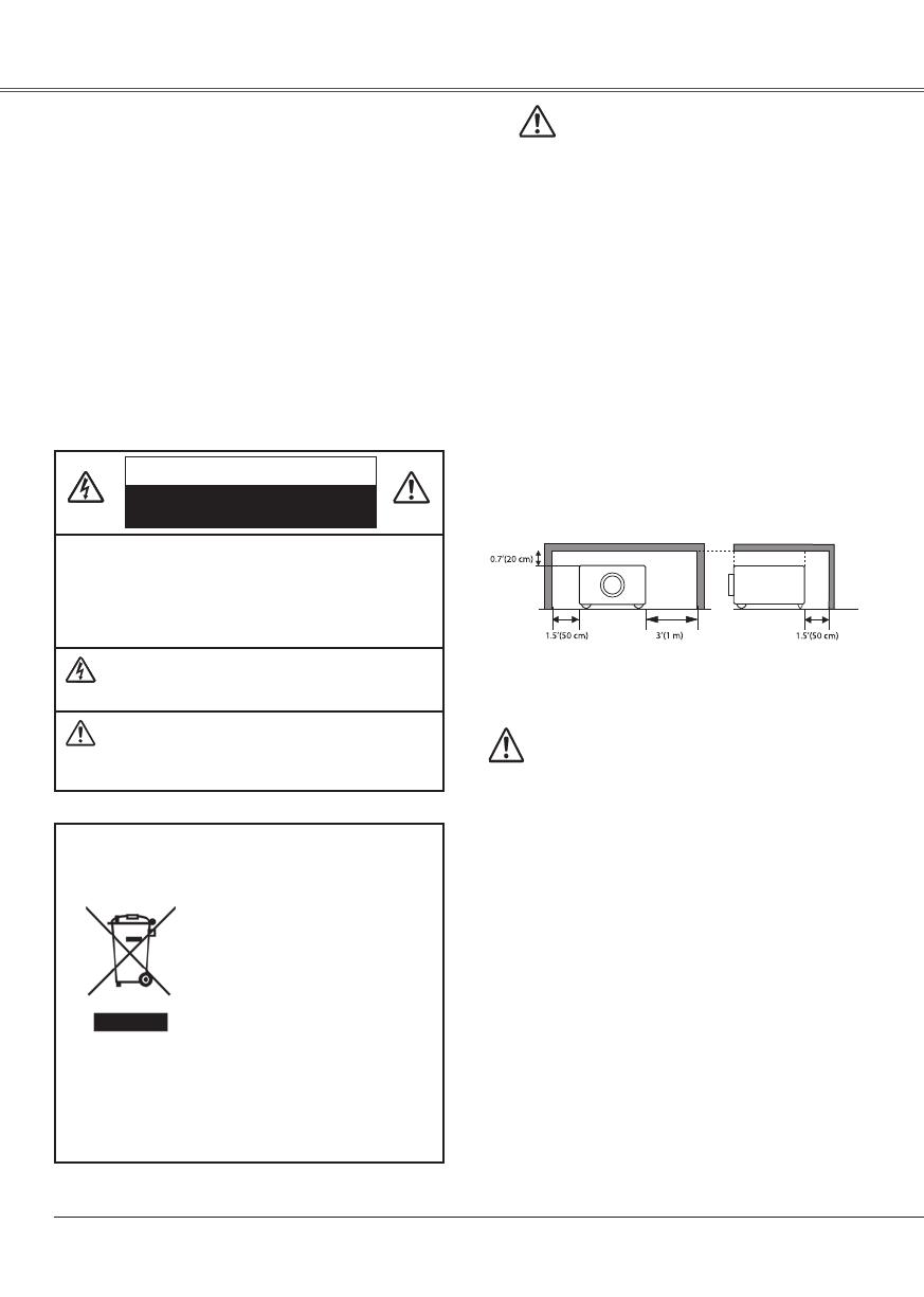
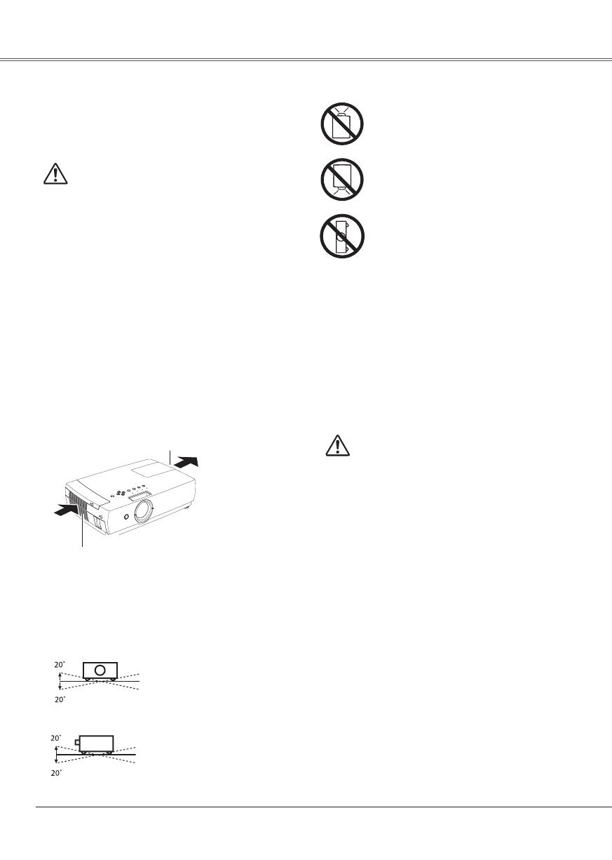
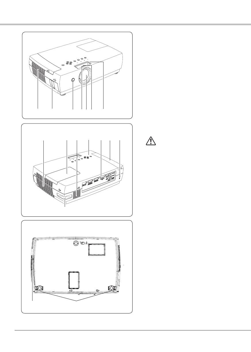
Slots and openings in the back and bottom of the cabinet
are provided for ventilation, to ensure reliable operation of
the equipment and to protect it from overheating.
The openings should never be covered with cloth or other
materials, and the bottom opening should not be blocked
by placing the projector on a bed, sofa, rug, or other
similar surface. This projector should never be placed
near or over a radiator or heat register.
This projector should not be placed in a built-in installation
such as a book case unless proper ventilation is provided.
Never push objects of any kind into this projector through
cabinet slots as they may touch dangerous voltage points
or short out parts that could result in a fire or electric
shock. Never spill liquid of any kind on the projector.
Do not install the projector near the ventilation duct of air-
conditioning equipment.
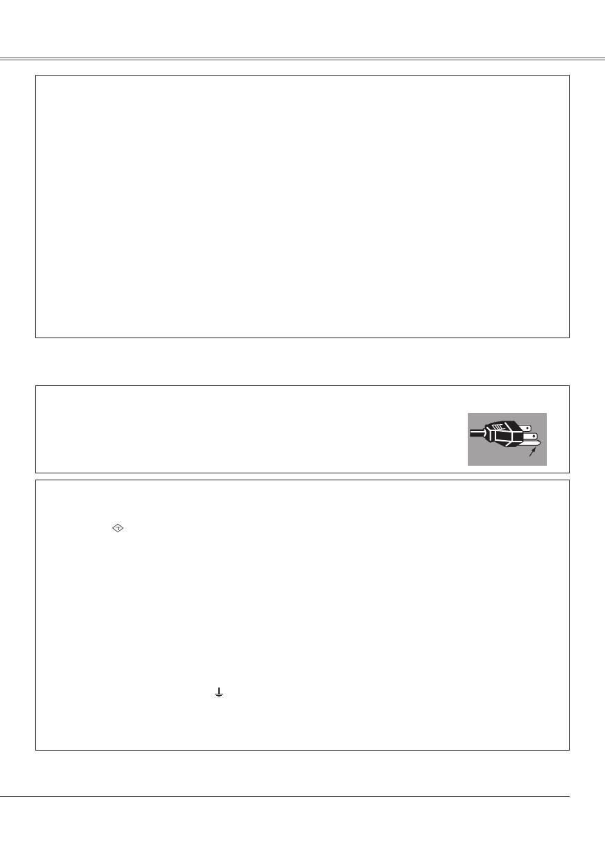
To the Owner
This projector should be operated only from the type of
power source indicated on the marking label. If you are not
sure of the type of power supplied, consult your authorized
dealer or local power company.
Do not overload wall outlets and extension cords as this
can result in fire or electric shock. Do not allow anything to
rest on the power cord. Do not locate this projector where
the cord may be damaged by persons walking on it.
Do not attempt to service this projector yourself as opening
or removing covers may expose you to dangerous voltage
or other hazards. Refer all servicing to qualified service
personnel.
Unplug this projector from wall outlet and refer servicing to
qualified service personnel under the following conditions:
a.When the power cord or plug is damaged or frayed.
b.If liquid has been spilled into the projector.
c.
If the projector has been exposed to rain or water
.
d.If the projector does not operate normally by following
the operating instructions. Adjust only those controls that
are covered by the operating instructions as improper
adjustment of other controls may result in damage and
will often require extensive work by a qualified technician
to restore the projector to normal operation.
e.If the projector has been dropped or the cabinet has
been damaged.
f.
W
hen the projector exhibits a distinct change in
performance-this indicates a need for service.
When replacement parts are required, be sure the service
technician has used replacement parts specified by the
manufacturer that have the same characteristics as the
original part. Unauthorized substitutions may result in fire,
electric shock, or injury to persons.
Upon completion of any service or repairs to this projector,
ask the service technician to perform routine safety
checks to determine that the projector is in safe operating
condition.
NOTE FOR CUSTOMERS INTHE US
Hg LAMP(S) INSIDE THIS PRODUCTCONTAIN MERCURY
AND MUST BE RECYCLED OR DISPOSED OF
ACCORDING TO LOCAL,STATE OR FEDERAL LAWS.
6
Compliance
Safety Instructions
Openings in the cabinet are provided for ventilation and to
ensure reliable operation of the product and to protect it
from overheating, and these openings must not be blocked
or covered.
CAUTION
Hot air is exhausted from the exhaust vent. When using
or installing the projector, the following precautions
should be taken.
D
o not put any flammable object or spray can near
the projector, hot air is exhausted from the ventilation
holes.
– Keep
the exhaust vent at least 3' (1 m) away from any
objects.
– D
o not touch a peripheral part of the exhaust vent,
especially screws and metallic part. This area will
become hot while the projector is being used.
– Do
not put anything on the cabinet. Objects put on the
cabinet will not only get damaged but also cause fire
hazard by heat.
Cooling fans are provided to cool down the projector.
The fans’ running speed is changed according to the
temperature inside the projector.
Air Circulation
Do not roll the projector more
than 20 degrees from side to
side.
Do not point the projector up to project an
image.
Do not point the projector down to project
an image.
Do not put the projector on either side to
project an image.
Install the projector properly. Improper Installation may
reduce the lamp life and cause a fire hazard.
Installing the Projector in Proper
Position
USE CAUTION IN CARRYING OR TRANSPORTING
THE PROJECTOR
– Do not drop or bump the projector, otherwise damages
or malfunctions may result.
– W
hen carrying the projector, use a suitable carrying
case.
– D
o not transport the projector by using a courier or
transport service in an unsuitable transport case. This
may cause damage to the projector. To transport the
projector through a courier or transport service, consult
your dealer for their information.
– Do
not put the projector in a case before the projector
is cooled enough.
Moving the Projector
When moving the projector, close the slide shutter and
retract the adjustable feet to prevent damage to the
lens and cabinet. When the projector is not in use
for an extended period, put it into a suitable case to
protect the projector.
When handling the projector, do not drop, bump,
subject it to strong forces, or put other things on the
cabinet.
Air Intake Vent
Exhaust Vent
(Hot air exhaust)
Air flow
Do not pitch the projector more
than 20 degrees above and
below.
7
Compliance
Federal Communications Commission Notice
Note: This equipment has been tested and found to comply with the limits for a Class B digital device, pursuant to
Part 15 of the FCC Rules. These limits are designed to provide reasonable protection against harmful interference in
a residential installation. This equipment generates, uses, and can radiate radio frequency energy, and if not installed
and used in accordance with the instructions, may cause harmful interference to radio communications. However,
there is no guarantee that interference will not occur in a particular installation. If this equipment does cause harmful
interference to radio or television reception, which can be determined by turning the equipment off and on, the user is
encouraged to try to correct the interference by one or more of the following measures:
Reorient or relocate the receiving antenna.
Increase the separation between the equipment and receiver.
– Connect the equipment into an outlet on a circuit different from that to which the receiver is connected.
– Consult the dealer or an experienced radio/TV technician for help.
Use of shielded cable is required to comply with class B limits in Subpart B of Part 15 of FCC Rules.
Do not make any changes or modifications to the equipment unless otherwise specified in the instructions. If such
changes or modifications should be made, you could be required to stop operation of the equipment.
Model Number
: PLC-XC50 / PLC-XC55
Trade Name : Sanyo
Responsible party : SANYO FISHER COMPANY
Address : 21605 Plummer Street, Chatsworth, California 91311
Telephone No. : (818)998-7322
The AC Power Cord supplied with this projector meets the requirement for use in the country you purchased it.
AC Power Cord for the United States and Canada:
AC Power Cord used in the United States and Canada is listed by the Underwriters
Laboratories (UL) and certified by the Canadian Standard Association (CSA).
AC Power Cord has a grounding-type AC line plug. This is a safety feature to be sure that the
plug will fit into the power outlet. Do not try to defeat this safety feature. Should you be unable
to insert the plug into the outlet, contact your electrician.
GROUND
AC Power Cord Requirement
AC Power Cord for the United Kingdom:
This cord is already fitted with a moulded plug incorporating a fuse, the value of which is indicated on the pin face of
the plug. Should the fuse need to be replaced, an ASTA approved BS 1362 fuse must be used of the same rating,
marked thus
ASA
. If the fuse cover is detachable, never use the plug with the cover omitted. If a replacement fuse
cover is required, ensure it is of the same colour as that visible on the pin face of the plug (i.e. red or orange). Fuse
covers are available from the Parts Department indicated in your User Instructions.
If the plug supplied is not suitable for your socket outlet, it should be cut off and destroyed.
The end of the flexible cord should be suitably prepared and the correct plug fitted.
WARNING : A PLUG WITH BARED FLEXIBLE CORD IS HAZARDOUS IF ENGAGED IN A LIVE SOCKET
OUTLET.
The Wires in this mains lead are coloured in accordance with the following code:
Green-and-yellow . . . . . . Earth
Blue. . . . . . . . . . . . . . . . . Neutral
Brown . . . . . . . . . . . . . . . Live
As the colours of the wires in the mains lead of this apparatus may not correspond with the coloured markings
identifying the terminals in your plug proceed as follows:
The wire which is coloured green-and-yellow must be connected to the terminal in the plug which is marked by the
letter E or by the safety earth symbol
or coloured green or green-and-yellow.
The wire which is coloured blue must be connected to the terminal which is marked with the letter N or coloured
black.
The wire which is coloured brown must be connected to the terminal which is marked with the letter L or coloured red.
W
ARNING: THIS
APPARATUS MUST BE EARTHED.
THE SOCKET-OUTLET SHOULD BE INSTALLED NEAR THE EQUIPMENT AND EASILY ACCESSIBLE.
8
Part Names and Functions
Air Intake Vent
Power Cord Connector
Infrared Remote Receiver
Focus Ring (front)
Lens and Lens cover
Zoom Ring (rear)
Slide Shutter
Exhaust Vent
CAUTION
Hot air is exhausted from the exhaust vent. Do not
put heat-sensitive objects near this side.
Lamp Cover
Speaker
Top Controls and Indicators
Terminals and Connectors
Filter Cover
Adjustable feet
Kensington Security Slot
This slot is for a Kensington lock used to deter
theft of the projector.
*Kensington is a registered trademark of ACCO Brands
Corporation.

Security Bar
A commercially available anti-theft chain or
wire can be attached to the security bar on the
projector.
Back
Front
Bottom

9
Part Names and Functions
Rear Terminal
MONITOR OUT
This terminal can be used to output the incoming
RGB signal from COMPUTER IN 1 / DVI-I
terminal or COMPUTER IN 2/COMPONENT IN
terminal to the other monitor (p.14).
CONTROL PORT
When the projector is controlled by a computer,
connect to this jack with serial control cable.
COMPUTER IN 2 / COMPONENT IN
Connect output signal from a computer, RGB
scart 21-pin video output or component video
output to this terminal. (pp.14,16)
AUDIO IN
Connect the audio output from video equipment
connected to
or to this jack. (When
the audio output is monaural, connect it to L
(MONO) jack.). (p.15)
VIDEO IN
Connect the composite video output from video
equipment to VIDEO jack. (p.15)
AUDIO OUT (VARIABLE)
Connect an external audio amplifier to this jack.
(pp.14 - 16)
T
h
is terminal outputs sound from AUDIO IN
terminal ( or ).
S-VIDEO IN
Connect the S-VIDEO output signal from video
equipment to this jack (p.15).
COMPUTER IN 1 / DVI-I
Connect computer output (Digital/Analog DVI-I
type) to this terminal (p.14).
COMPUTER1/ COMPUTER2 COMPONENT
AUDIO IN
Connect the audio output (stereo) from a
computer or video equipment connected to
or
to this jack. (pp14, 16)
10
Top Control
LAMP REPLACE indicator
Turn yellow when the life of the projection lamp
draws to an end. (pp.60, 71-72)
WARNING FILTER indicator
Blink slow when the filter is being scrolled .
(pp.57, 71)
Blink fast when the filter cartridge is not
installed. (pp.57, 72)
Light orange when the clogging of the filter is
detected or the filter counter reaches a time
set in the timer setting, urging immediate filter/
filter cartridge replacement. (pp.55, 57, 72)
POWER ON/STAND-BY button
Turn the projector on or off. (pp.18, 19)
POWER indicator
Light red when the projector is in stand-by
mode.
Light green during operations.
Blink green in the Power management mode .
(p.50)
Blink red during cooling down.
MENU button
Open or close the On-Screen Menu. (p.20)
POINT (▲▼) buttons
Select an item or adjust the value in the
On-Screen Menu. (p.20)
Pan the image in Digital zoom + mode.
(p.36)
SELECT button
Execute the selected item. (p.20)
Expand or compress the image in Digital
zoom mode. (p.36)
Part Names and Functions Part Names and FunctionsPart Names and Functions
POINT (◄►) buttons
Select an item or adjust the value in the
On-Screen Menu. (p.20)
Pan the image in Digital zoom + mode.
(p.36)
AUTO SETUP button
Execute the setting of Auto setup (includes
Input search, Auto PC adj. and Auto Keystone
functions) in the setting menu.
(pp.22,24,28,46)
WARNING TEMP. indicator
Emit a red light when the projector detects
an abnormal condition. This also blinks red
when the internal temperature of the projector
exceeds the operating range. (pp.63, 71-72)
INPUT button
Select an input source. (pp.25-26, 37-38)
11
Part Names and Functions Part Names and FunctionsPart Names and Functions
Remote Control
POWER ON/STAND-BY button
Turn the projector on or off. (pp.18, 19)
VIDEO button
Select VIDEO input source. (p.37)
COMPUTER 1 button
Select Computer 1 (Analog) or Computer 1 (Digital)
input source. (pp.25, 26)
MENU button
Open or close the On-Screen Menu. (p.20)
D.ZOOM ▲▼ buttons
Zoom in and out the images. (pp.24, 36)
AUTO SET button
E
xecute t
he setting of Auto setup (includes Input
search function, Auto PC adj. function and Auto
Keystone function). (pp.22, 24, 28, 46)
IMAGE button
Select the image level. (pp.24, 31, 40)
FREEZE button
Freeze the picture. (p.23)
MUTE button
Mute the sound. (p.23)
P-TIMER button
Operate the P-timer function. (p.24)
NO SHOW button
Temporarily turn off the image on the screen. (p.24)
KEYSTONE button
Correct the keystone distortion. (pp.22, 47)
Point ▲▼◄► buttons
– Select an item or adjust the value in the On-
Screen Menu. (p.20)
– Pan the image in Digital zoom + mode. (p.36)
SELECT button
– Execute the selected item. (p.20)
– Expand or compress the image in Digital zoom
mode. (p.36)
LAMP CONTROL button
Select the lamp mode. (pp.24, 51)
To ensure safe operation, please observe
the following precautions:
– Do not bend, drop or expose the remote
control to moisture or heat.
– For cleaning, use soft dry cloth. Do not
apply benzene, thinner, spray or any
chemical material.
1
2
+
_
COMPUTER 2 button
Select COMPUTER 2 input source. (pp.25, 38)
S-VIDEO button
Select S-VIDEO input source. (p.37)
COMPONENT button
Select COMPONENT input source. (p. 38)
VOLUME + / – buttons
Adjust the volume level. (p.23)
12
Installation
Part Names and Functions
To ensure safe operation, please observe the following precautions:
Use two (2) AA or LR6 type alkaline batteries.
Always replace batteries in sets.
Do not use a new battery with a used battery.
Avoid contact with water or liquid.
Do not expose the remote control to moisture or heat.
Do not drop the remote control.
If the battery has leaked on the remote control, carefully wipe the case clean and install new
batteries.
Risk of explosion if a battery is replaced by an incorrect type.
Dispose of used batteries according to the instructions.
Open the battery
compartment lid.
Install new batteries
into the compartment.
Replace the
compartment lid.
Two AA size batteries
For correct polarity
(+ and –), be sure
battery terminals are in
contact with pins in the
compartment.
Remote Control Battery Installation
1 2 3
Point the remote control toward the
projector (Infrared Remote Receiver)
when pressing any button. Maximum
operating range for the remote control is
about 16.4' (5 m) and 60° in front of the
projector.
Operating Range
16.4'
(5 m)
13
Installation
Part Names and Functions
Notes:
The brightness in the room has a great influence on picture quality. It is recommended to limit ambient
lighting in order to obtain the best image.
The values shown below are approximate and may vary from the actu
al sizes.
Positioning the Projector
Screen Size
(W x H) mm
4 : 3 aspect ratio
Zoom (min)
40"
Zoom (max)
813 x 610
5.5' (1.7 m)
100"
2032 x 1524
13.9' (4.2 m)
11.6' (3.5 m)
150"
3048 x 2286
20.9' (6.4 m)
17.4' (5.3 m)
200"
4064 x 3048
27.8' (8.5 m)
23.2' (7.1 m)
300"
6096 x 4572
41.8' (12.7 m)
34.8' (10.6 m)
4.6' (1.4 m)
11.6' (3.5 m)
4.6' (1.4 m)
17.4' (5.3 m)
23.2' (7.1 m)
34.8' (10.6 m)
41.8' (12.7 m)
For projector positioning, see the figures below. The projector should be set horizontally to the flat screen.
Projection angle can be adjusted up to 10.0 degrees with the adjustable feet.
Lift the front of the projector and push the feet lock
latches on the projector.
1
Release the feet lock latches to lock the adjustable
feet and rotate the adjustable feet to adjust the
position and tilt.
To retract the adjustable feet, lift the front of the
projector and push and undo the feet lock latches.
Keystone distortion of the projected image can be
corrected with the remote control or menu operation.
(pp.22, 46)
Adjustable Feet
2
3
Adjustable Feet Feet Lock Latches
14
Installation
Connecting to a Computer
Cables used for connection
• DVI Cable or DVI-VGA Cable
• VGA Cables (Mini D-sub 15 pin) (Only one cable is supplied.)
Audio Cables (Mini Plug: stereo)
( Not all the cables are supplied with this projector.)
Notes:
Input sound to the COMPUTER 2 / COMPONENT AUDIO IN terminal when using the COMPUTER IN 2
/COMPONENT IN as input.
Input
sound to the COMPUTER 1 AUDIO IN terminal when using the COMPUTER IN 1 / DVI-I terminal
as input.
When the
AUDIO OUT is plugged-in, the projector's built-in speaker is not available.
Unplug the power cords of both the projector and external equipment from the AC outlet before
connecting cables.
External Audio Equipment
VGA
cable
Audio cable
(stereo)
Monitor Output
COMPUTER 2
/ COMPONENT
/COMPUTER 1
AUDIO IN
AUDIO OUT
(stereo)
Audio Input
Monitor Output
COMPUTER IN 2
/COMPONENT IN
DVI-VGA
cable
COMPUTER IN
1/ DVI-I
VGA
cable
Audio cable
(stereo)
Audio Output
Installation
Monitor Input
MONITOR OUT
DVI
cable
15
Installation Installation
Connecting to Video Equipment
Cables used for connection
• Video and Audio Cable (RCA x 3)
• S-video Cable
Audio Cables (RCA x 2, Mini Plug: stereo)
(Cables are not supplied with the projector.)
Unplug the power cords of both the projector and external equipment from the AC outlet before
connecting cables.
Note:
When the AUDIO OUT is plugged-in, the projector's built-in speaker is not available.
External Audio Equipment
Audio cable
(stereo)
S-VIDEO IN
S-video
cable
Video and
Audio cable
Composite Video and Audio Output
S-video Output
Audio Input
AUDIO OUT
(stereo)
(R) (L)
(R) (L) (Video)
(Video)(R) (L)
(R) (L)
Audio cable
(stereo)
16
Installation
Connecting to Component Video and RGB (Scart) Equipment
Cables used for connection
Audio Cables (Mini Plug :stereo)
• Scart-VGA Cable
• Component Cable
• Component-VGA Cable
(Cables are not supplied with the projector.)
Notes:
When the AUDIO OUT is plugged-in, the projector's built-in speaker is not available.
See page 76 for ordering optional parts.
Unplug the power cords of both the projector and external equipment from the AC outlet before
connecting cables.
External Audio Equipment
COMPUTER IN 1/COMPONENT IN
COMPUTER2/
COMPONENT
AUDIO IN
Audio cable
(stereo)
Audio cable (stereo)
Audio Input
Component Video Output
(Y, Pb/Cb, Pr/Cr)
RGB Scart
21-pin Output
Audio Output
Scart-VGA
cable
Component-VGA cable
AUDIO OUT
(stereo)
Component cable
Installation
17
Installation
To the AC outlet.
(200 - 240 V AC)
Installation
This projector uses nominal input voltages of 100-120 V
or 200-240 V AC. This projector automatically selects
the correct input voltage. It is designed to work with
single-phase power systems having a grounded neutral
conductor. To reduce the risk of electrical shock, do not
plug into any other type of power system.
Consult your authorized dealer or service station if you are
not sure of the type of power being supplied.
Connect the projector with all peripheral equipment before
turning the projector on. (See pages 14-16 for connection)
Connecting the AC Power Cord
NOTE ON THE POWER CORD
AC power cord must meet requirement of the country where you use the projector.
Confirm the AC plug type with the chart below and proper AC power cord must be used.
If supplied AC power cord does not match your AC outlet, contact your sales dealer.
To power cord
connector on your
projector.
Projector side
AC outlet side
Ground
To the AC outlet.
(120 V AC)
For the U.S.A. and Canada
To the AC outlet.
(200 - 240 V AC)
CAUTION
The AC outlet must be near this equipment and must be easily
accessible.
For the U.K.For Continental Europe
Note:
Unplug the AC power cord when the projector is not in use.
When this projector is connected to an outlet with the AC
power cord, it is in Stand-by mode and consumes a little
electric power.
Connect the AC power cord
(supplied) to the projector.
18
Basic Operation
Connect the projectors AC power cord into an AC
outlet. The POWER indicator becomes red.
Press the POWER ON/STAND-BY button on the
top control or on the remote control. The POWER
indicator becomes green and the cooling fans start
to operate. The preparation display appears on the
screen and the count down starts.
2
3
1
4
After the countdown, the input source that was
selected the last time and the Lamp mode status icon
(see page 51) appears on the screen.
Complete peripheral connections (with a computer,
VCR, etc.) before turning on the projector.
Turning On the Projector
To Enter a PIN code
Select a number by pressing the Point ▲▼ buttons,
and then press the Point
button to fix the number
and move the pointer. The number changes to "". If
you fixed an incorrect number, move the pointer to the
number you want to correct by pressing the Point
button, and then select the correct number by pressing
the Point
▲▼ buttons.
Repeat this step to complete entering a four-digit
number.
"1234" is set as the initial PIN code at the factory.
After entering the four-digit number, move the pointer
to "Set" by pressing the Point
button. Press the
SELECT button so that you can start to operate the
projector.
If you entered an incorrect PIN code, "PIN code" and
the number () turns red. Enter the correct PIN
code all over again.
What is PIN code?
PIN (Personal Identification Number) code that allows
the person who knows it to operate the projector.
Setting a PIN code prevents unauthorized use of the
projector.
A PIN code consists of a four-digit number. Refer to the
PIN code lock function in the Setting on pages 53 and
54 for locking operation of the projector with your PIN
code.
CAUTION ON HANDLING PIN CODE
If you forget your PIN code, the projector can no longer
be started. Set a new PIN code with special care,
write it down in column on page 79 of this manual, and
k
e
ep it on hand. Should the PIN code be missing or
forgotten, consult your dealer or service center.
16
The preparation display disappears after 30
seconds.
(See page 51 for Lamp mode.)
Note:
The Filter warning and Lamp replacement icons
may appear on the screen depending on the
usage state of the projector.
Selected Input Source and Lamp Mode
Lamp mode
After the OK icon
disappears, you can
operate the projector.
PIN Code Input Dialog Box
If the projector is locked with a PIN code, PIN code
Input Dialog Box appears. Enter the PIN code as
instructed below.
Notes:
W
hen the Input Search function is set
On1 or On2, the input signal will be
searched automatically (p.46)
When the Logo select function is off,
the logo is not shown on the screen.
(p.48)
W
hen the "Countdown off" or "Off" is
selected in the Display function, the
countdown is not shown on the screen.
(p.47)
D
uring the countdown period, all
operations are invalid.
If
the PIN code number is not input for
three minutes after the PIN code dialog
box appeared, the projector is turned off
automatically.
Basic Operation
19
Basic Operation
Basic Operation
Press the POWER ON/STAND-BY button on the
top control or on the remote control, and a message
"Power off?" appears on the screen.
Press the POWER ON/STAND-BY button again to
turn off the projector.The POWER indicator starts to
blink red, and the cooling fans keep running. (You can
select the level of fan quietness and rotation speed.
See page 55.)
At this time you can disconnect the AC power cord
even if the fans are still running.
1
2
TO MAINTAIN THE LIFE OF THE LAMP, ONCE
YOU TURN THE PROJECTOR ON, WAIT AT
LEAST FIVE MINUTES BEFORE TURNING IT OFF.
3
When the projector has cooled down enough, the
POWER indicator stops blinking and you can turn on
the projector.
Turning Off the Projector
Notes:
When the On start function is on, this projector is turned on automatically by connecting the AC power
cord to an AC outlet. (p.51)
The running speed of cooling fans is changed according to the tempe
rature inside the projector.
Do not put the projector in a case before the projector is cooled enough.
If the WARNING TEMP. indicator blinks or emits a red light, see "Indicators and Projector Condition" on
pages 71-72.
While
the POWER indicator is blinking, lamp is being cooled down and the projector cannot be turned
on. Wait until the POWER indicator stops blinking to be turned on again.
• The
fan rotation will terminate directly if the AC power cord is unplugged immediately after the projector
is turned off.
The
projector can be turned on after the POWER indicator turns red. The waiting time to restart will be
shortened when the normal power-off processing for fan cooling is completed, compared with the time
the AC power cord is immediately unplugged after the power-off.
The message disappears after 4 seconds.
DO N O T O P ER ATE TH E P R OJ EC TO R
CONTINUOUSLY WITHOUT REST.CONTINUOUS
USE MAY RESULT IN SHORTENTING THE LAMP
LIFE.TURN OFF THE PROJECTOR AND GIVE IT A
REST ABOUT AN HOUR IN EVERY 24 HOURS.
20
Basic Operation
How to Operate the On-Screen Menu
The projector can be adjusted or set via the On-Screen
Menu. Refer to the following pages regarding each
adjustment and setting procedures.
Press the Point
◄► buttons to select a Menu icon to
adjust and press the Point
▲▼ buttons to select an
item to adjust.
Press the SELECT button to show the item data. To
adjust the data, press the Point
◄► buttons. Refer to
the following pages for each adjustment.
To close the On-Screen Menu, press the MENU button
again.
Press the MENU button to display the On-Screen
Menu.
Note:
The selected item is not active until the SELECT
button is pressed.
1
2
3
Top Control
1
2
+
_
SELECT button
POINT buttons
Remote Control
MENU button
Menu bar
Pointer
(red frame )
Menu icon
Item data
Press the Point
buttons to adjust the
value.
SELECT
button
Pointer (red frame )
Press the Point
▲▼ buttons to
move the pointer.
Item
On-Screen Menu
Quit
Exit this menu.
MENU button SELECT button
POINT buttons
(outer ring)
Basic Operation
Press the SELECT button here
to display previous items.
Press the SELECT button here to
display next items.
  • Page 1 1
  • Page 2 2
  • Page 3 3
  • Page 4 4
  • Page 5 5
  • Page 6 6
  • Page 7 7
  • Page 8 8
  • Page 9 9
  • Page 10 10
  • Page 11 11
  • Page 12 12
  • Page 13 13
  • Page 14 14
  • Page 15 15
  • Page 16 16
  • Page 17 17
  • Page 18 18
  • Page 19 19
  • Page 20 20
  • Page 21 21
  • Page 22 22
  • Page 23 23
  • Page 24 24
  • Page 25 25
  • Page 26 26
  • Page 27 27
  • Page 28 28
  • Page 29 29
  • Page 30 30
  • Page 31 31
  • Page 32 32
  • Page 33 33
  • Page 34 34
  • Page 35 35
  • Page 36 36
  • Page 37 37
  • Page 38 38
  • Page 39 39
  • Page 40 40
  • Page 41 41
  • Page 42 42
  • Page 43 43
  • Page 44 44
  • Page 45 45
  • Page 46 46
  • Page 47 47
  • Page 48 48
  • Page 49 49
  • Page 50 50
  • Page 51 51
  • Page 52 52
  • Page 53 53
  • Page 54 54
  • Page 55 55
  • Page 56 56
  • Page 57 57
  • Page 58 58
  • Page 59 59
  • Page 60 60
  • Page 61 61
  • Page 62 62
  • Page 63 63
  • Page 64 64
  • Page 65 65
  • Page 66 66
  • Page 67 67
  • Page 68 68
  • Page 69 69
  • Page 70 70
  • Page 71 71
  • Page 72 72
  • Page 73 73
  • Page 74 74
  • Page 75 75
  • Page 76 76
  • Page 77 77
  • Page 78 78
  • Page 79 79
  • Page 80 80

Sanyo plc xc55 User manual

Category
Data projectors
Type
User manual

Ask a question and I''ll find the answer in the document

Finding information in a document is now easier with AI