Page is loading ...

Page 1
98350C (Rev. D - 9/09)
HACFSCDBL*D HACFSCDDBL*D HACFSCDDBLR*D HACFSCWFDBL*D HACFSCWFDDBL*D
HAC8FSCBLQ*1D HAC8FSCBLRQ*1D HAC8FSCWFBL*1D
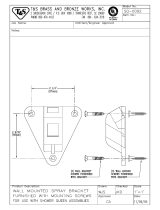
FIG. 1
HAC8FSCBL SHOWN
NOTE: Non-refrigerated units do not include all electrical and refrigeration components shown above. Other components and rough-in are the same as shown.
HALSEY TAYLOR OWNERS MANUAL
BI-LEVEL BARRIER FREE COOLER
USES HFC-134A REFRIGERANT
32,33,35,
36,37,38,39
65
17
22 (BL)
23 (BLR)
43
31
6
8
46
44
2,3,4,5
9
8
9
10,11
45
40
19
65
45
20 (BL)
21 (BLR)
28,29,30
45
See Fig. 4 (Page 4) For
Push Bar Mechanism
1
42
33,34,35,
36,37,38,39
42
24,25,26
27
18
45
17
40 10,11
65
12
13
7
45
41

Page 2
HACFSCDBL*D HACFSCDDBL*D HACFSCDDBLR*D HACFSCWFDBL*D HACFSCWFDDBL*D
HAC8FSCBLQ*1D HAC8FSCBLRQ*1D HAC8FSCWFBL*1D
98350C (Rev. D - 9/09)
12 5/16"
313mm
3 1/2"
89mm
4 1/2"
114mm
18 3/4"
476mm
6 1/4"
159mm
20 1/8"
511mm
25 1/8"
638mm
20 3/8"
518mm
2 7/16"
63mm
5"
127mm
10"
254mm
A
D
F
B
FINISHED FLOOR
PISO ACABADO
PLANCHER FINI
*
HANGER BRACKET
FIJADOR DE SUSPENSION
SUPPORT DE SUSPENSION
13 7/8"
352mm
37 1/2"
952mm
1 3/8"
35mm
1 3/8"
35mm
5 3/4"
146mm
5 3/4"
146mm
1 3/8"
35mm
1 3/8"
35mm
5 3/4"
146mm
5 3/4"
146mm
6 1/2"
165mm
18 1/16"
459mm
11/16"
18mm
4 9/16"
116mm
2 9/16"
65mm
7 1/4"
185mm
E
F
5/16" (8mm) DIA. (10 HOLES)
8mm (10 TROUS)
8MM (10 AGUJEROUS)
RIM HEIGHT
ALTURA DE LA
CORONA
HAUTEUR DE
BORD
ORIFICE HEIGHT
ALTURA DE LA
ORIFICIO
HAUTEUR DE
L'ORIFICE
ORIFICE HEIGHT
ALTURA DE LA
ORIFICIO
HAUTEUR DE
L'ORIFICE
L
C
L
C
27"
686mm
31 7/8"
809mm
33"
838mm
39 1/2"
1003mm
C
4 1/8"
105mm
18 5/8"
473mm
2 5/8"
67mm
6 3/4"
172mm
8"
203mm
E
FIG. 2
* ADA REQUIREMENT
* REQUISITO DE A.D.A.
* EXIGENCE ADA
REDUCE HEIGHT BY 3" FOR INSTALLATION OF CHILDRENS ADA COOLER
HAC8FSCBL
LEGEND/LEYENDA/LÉGENDE
A = RECOMMENDED WATER SUPPLY LOCATION. SHUT OFF VALVE (NOT FURNISHED) TO ACCEPT 3/8 O.D. UNPLATED COPPER TUBE.
POSICIÓN DE ABASTECIMIENTO DE AGUA RECOMENDADA. VÁLVULA CERRADA (NO AMUEBLADO) PARA ACEPTAR 3/8" O.D. TUBO DE
COBRE NO PLATEADO.
ENDROIT D’APPROVISIONNEMENT EN EAU RECOMMANDÉ. LA VALVE ARRÊTÉE (NON FOURNI) POUR ACCEPTER 3/8" PO. (9,5mm)
TUBE COULEUR CUIVRE NON PLAQUÉ.
B = RECOMMENDED LOCATION FOR WASTE OUTLET 1-1/2” O.D. DRAIN
UBICACIÓN RECOMENDADA PARA EL DRENAJE DE SALIDA DE AGUA, DE 1-1/2 DE DIÁMETRO.
EMPLACEMENT RECOMMANDÉ POUR LE DRAIN DE D.E. 1-1/2 DE SORTIE D’EAU.
C = 1-1/2" TRAP NOT FURNISHED**
PURGADOR DE 1-1/2 NO PROPORCIONADO**
SIPHON 1-1/2 NON FOURNI**
D = ELECTRICAL SUPPLY (3) WIRE RECESSED BOX
CAJA RECESIVA DE ALAMBRES (3) DE SUMINISTRO ELÉCTRICO
BOÎTE ENCASTRÉE D’ALIMENTATION ÉLECTRIQUE (3) FILS
E = INSURE PROPER VENTILATION BY MAINTAINING 6" (152 mm) (MIN.) CLEARANCE FROM CABINET LOUVERS TO WALL.
ASEGURE UNA VENTILACIÓN ADECUADA MANTENIENDO UN ESPACIO E 6" (152 mm) (MÍN.) DE HOLGURA ENTRE LA REJILLA DE
VENTILACIÓN DEL MUEBLE Y LA PARED
ASSUREZ-VOUS UNE BONNE VENTILATION EN GARDANT 6" (152 mm) (MIN.) ENTRE LES ÉVENTS DE L’ENCEINTE ET LE MUR.
F = 7/16 BOLT HOLES FOR FASTENING UNIT TO WALL
AGUJEROS DE LAS TUERCAS DE 7/16 PARA SUJETAR LA UNIDAD A LA PARED
TROUS D’ÉCROUS 7/16 POUR FIXER L’APPAREIL AU MUR

Page 3
98350C (Rev. D - 9/09)
HACFSCDBL*D HACFSCDDBL*D HACFSCDDBLR*D HACFSCWFDBL*D HACFSCWFDDBL*D
HAC8FSCBLQ*1D HAC8FSCBLRQ*1D HAC8FSCWFBL*1D
*
HANGER BRACKET
FIJADOR DE SUSPENSION
SUPPORT DE SUSPENSION
RIM HEIGHT
ALTURA DE LA
CORONA
HAUTEUR DE
BORD
ORIFICE HEIGHT
ALTURA DE LA
ORIFICIO
HAUTEUR DE
L'ORIFICE
ORIFICE HEIGHT
ALTURA DE LA
ORIFICIO
HAUTEUR DE
L'ORIFICE
L
C
L
C
C
13 7/8"
352mm
7 1/4"
185mm
2 9/16"
65mm
6 1/4"
159mm
11/16"
18mm
4 9/16"
116mm
18 3/4"
476mm
37 1/2"
952mm
6 1/2"
165mm
18 1/16"
459mm
5 3/4"
146mm
5 3/4"
146mm
5 3/4"
146mm
5 3/4"
146mm
1 3/8"
35mm
1 3/8"
35mm
1 3/8"
35mm
1 3/8"
35mm
2 7/16"
63mm
5"
127mm
10"
254mm
20 3/8"
518mm
26 11/16"
678mm
31 11/16"
805mm
3 1/2"
89mm
4 1/2"
114mm
5/16" (8mm) DIA. (10 HOLES)
8mm (10 TROUS)
8mm (10 AGUJEROUS)
12 5/16"
313mm
27"
686mm
4 1/8"
105mm
18 5/8"
473mm
2 5/8"
67mm
31 7/8"
810mm
33"
838mm
39 1/2"
1003mm
B
E
E
D
A
F
F
FINISHED FLOOR
PISO ACABADO
PLANCHER FINI
6 3/4"
172mm
8"
203mm
FIG. 3
* ADA REQUIREMENT
* REQUISITO DE A.D.A.
* EXIGENCE ADA
REDUCE HEIGHT BY 3" FOR INSTALLATION OF CHILDRENS ADA COOLER
HAC8FSCBLR
LEGEND/LEYENDA/LÉGENDE
A = RECOMMENDED WATER SUPPLY LOCATION. SHUT OFF VALVE (NOT FURNISHED) TO ACCEPT 3/8 O.D. UNPLATED COPPER TUBE.
POSICIÓN DE ABASTECIMIENTO DE AGUA RECOMENDADA. VÁLVULA CERRADA (NO AMUEBLADO) PARA ACEPTAR 3/8" O.D. TUBO DE
COBRE NO PLATEADO.
ENDROIT D’APPROVISIONNEMENT EN EAU RECOMMANDÉ. LA VALVE ARRÊTÉE (NON FOURNI) POUR ACCEPTER 3/8" PO. (9,5mm)
TUBE COULEUR CUIVRE NON PLAQUÉ.
B = RECOMMENDED LOCATION FOR WASTE OUTLET 1-1/2” O.D. DRAIN
UBICACIÓN RECOMENDADA PARA EL DRENAJE DE SALIDA DE AGUA, DE 1-1/2 DE DIÁMETRO.
EMPLACEMENT RECOMMANDÉ POUR LE DRAIN DE D.E. 1-1/2 DE SORTIE D’EAU.
C = 1-1/2" TRAP NOT FURNISHED**
PURGADOR DE 1-1/2 NO PROPORCIONADO**
SIPHON 1-1/2 NON FOURNI**
D = ELECTRICAL SUPPLY (3) WIRE RECESSED BOX
CAJA RECESIVA DE ALAMBRES (3) DE SUMINISTRO ELÉCTRICO
BOÎTE ENCASTRÉE D’ALIMENTATION ÉLECTRIQUE (3) FILS
E = INSURE PROPER VENTILATION BY MAINTAINING 6" (152 mm) (MIN.) CLEARANCE FROM CABINET LOUVERS TO WALL.
ASEGURE UNA VENTILACIÓN ADECUADA MANTENIENDO UN ESPACIO E 6" (152 mm) (MÍN.) DE HOLGURA ENTRE LA REJILLA DE
VENTILACIÓN DEL MUEBLE Y LA PARED
ASSUREZ-VOUS UNE BONNE VENTILATION EN GARDANT 6" (152 mm) (MIN.) ENTRE LES ÉVENTS DE L’ENCEINTE ET LE MUR.
F = 7/16 BOLT HOLES FOR FASTENING UNIT TO WALL
AGUJEROS DE LAS TUERCAS DE 7/16 PARA SUJETAR LA UNIDAD A LA PARED
TROUS D’ÉCROUS 7/16 POUR FIXER L’APPAREIL AU MUR

Page 4
HACFSCDBL*D HACFSCDDBL*D HACFSCDDBLR*D HACFSCWFDBL*D HACFSCWFDDBL*D
HAC8FSCBLQ*1D HAC8FSCBLRQ*1D HAC8FSCWFBL*1D
98350C (Rev. D - 9/09)
COOLER BACK
SUPPORT DE SUSPENSION
ARRIÈRE DU REFROIDISSEUR
HANGER BRACKET
FIJADOR DE SUSPENSIÓN
SUPPORT DE SUSPENSION
PUSH BAR MECHANISM
IMPORTANT
ALL SERVICE TO BE PERFORMED BY AN
AUTHORIZED SERVICE PERSON
HANGER BRACKETS & TRAP
INSTALLATION
1) Remove hanger brackets fastened to back of cooler by
removing one (1) screw.
2) Mount the hanger brackets and trap as shown in Figures 2 or 3.
NOTE: Hanger Brackets MUST be supported securely. Add
fixture support carrier if wall will not provide adequate support.
IMPORTANT:
y 4 1/8 in. (105mm) dimension from wall to centerline of trap must
be maintained for proper fit.
y Anchor hanger securely to wall using all five (5) 5/16" dia.
mounting holes.
3) Install straight valve for 3/8" O.D. tube.
INSTALLATION OF COOLER
4) Hang the cooler on the hanger bracket. Be certain the
hanger bracket is engaged properly in the slots on the cooler
back as shown in Fig. 5.
5) Loosen the two (2) screws holding the lower front panel at
the bottom of cooler base and two (2) screws at the top.
Remove the front panel and set aside.
6) Connect water inlet line--See Note 4 of General Instructions.
7) Remove the slip nut and gasket from the trap and install
them on the cooler waste line making sure that the end of
the waste line fits into the trap. Assemble the slip nut and
gasket to the trap and tighten securely.
START UP
Also See General Instructions
8) Stream height is factory set at 45-50 PSI. If supply
pressure varies greatly from this, readjust stream height to
approximately 1-1/2" (38mm) above the bubbler guard by
turning adjustment screw, accessible by removing front push
panel. Item No. 16 (see Fig. 4 & 6).
9) Replace the front panel and secure by retightening four (4)
screws.
10) If a taste, odor or sediment problem is prevalent, try
installing our water filter module.
FIG. 4
CORRECT STREAM HEIGHT
FIG. 5
FIG. 6
LEGEND
A) Note: Water flow direction
B) Adjust this screw to eliminate mechanism “Free Play” or continuous flow
from bubbler conditions. (See ADJUSTMENT PROCEDURE)
C) Stream height adjustment (see note #8)
Water Valve Mechanism - ADJUSTMENT PROCEDURE:
- Turn adjustment screw (Item 62) “Counter-Clockwise” until water flow from bubbler
starts.
- Turn adjustment screw “Clockwise” until water flow stops, THEN turn an additional
1/2 turn.
NOTE: Adjustments stated above are viewed from underneath unit (bottom side of
dispenser panel Item 48)
NOTE: If continuous flow occurs at the end of the compressor cycle, turn cold control
(Item 43) counterclockwise 1/4 turn.
14
54
50
53
16
51
52
54
56
C
50
64
15
52
51
54
55
54
63
49
48
49
59
57
60
61
A
62 - B
66
66
47
58

Page 5
98350C (Rev. D - 9/09)
HACFSCDBL*D HACFSCDDBL*D HACFSCDDBLR*D HACFSCWFDBL*D HACFSCWFDDBL*D
HAC8FSCBLQ*1D HAC8FSCBLRQ*1D HAC8FSCWFBL*1D
PRINTED IN U.S.A.
2222 CAMDEN COURT
OAK BROOK, IL 60523
630.574.3500
ITEMIZED PARTS LIST
ITEM
NO
DESCRIPTION
1
2
3
4
5
6
7
8
9
10
11
12
13
14
15
16
17
18
19
20
21
22
23
24
25
26
*27
28
29
30
31
32
32A
33
34
34A
35
36
37
38
39
40
41
42
43
44
45
46
47
48
49
50
51
52
53
54
55
56
57
58
59
60
61
62
63
64
65
66
NS
36208C
30664C
70018C
31490C
70009C
56237C
70682C
75524C
56159C
51544C
100322740560
66743C
66703C
See Color Table
See Color Table
See Color Table
See Color Table
See Color Table
See Color Table
See Color Table
See Color Table
See Color Table
See Color Table
101474551730
100806740570
19037000
36094C
35959C
35768C
36158C
66576C
45895C
45895C
75589C
45895C
45895C
56121C
75588C
100147140560
102639931640
160270508640
28702C
75583C
56092C
31513C
66534C
70002C
55996C
55931C
22897C
51531C
111411743620
55859C
55947C
22900C
70864C
50212C
51667C
40045C
23003C
15005C
61314C
50986C
70935C
75532C
22901C
45876C
50129C
28551C
PART NO
Power Cord
Fan Blade
Hex Nut - Fan Blade
Fan Motor
Screw - (Fan Motor)
Shroud - Fan
Fitting - Tee 1/4"
Clip (Front and Rear Panels)
Nipple - Bubbler
Bubbler - Chrome
Gasket - Bubbler (upper and lower)
Condenser
Drier
Panel - Left Side
Panel - Right Side
Panel - Front Push
Panel - Front Lower
Panel - Right Rear
Panel - Left Rear
Panel - Right Rear BL
Panel - Right Rear BLR
Panel - Left Rear BL
Panel - Left Rear BLR
Stud - Compressor Mtg.
Grommet - Compressor Mtg.
Clip - Compressor Mtg.
Compressor Serv. Pak EMI 70 HNR
Relay
Cover - Relay
Overload
Heat Exchanger
Waste Line BL (Left Unit)
Waste Line BLR (Left Unit)
Gasket
Waste Line BL (Refrig. Unit)
Waste Line BLR (Refrig. Unit)
Fitting - Elbow 1-1/4
Nut - Slip Joint 1-1/4
Gasket - Drain
Drain Plug - Chrome
Strainer Plate - Chrome
Basin - Stainless Steel
Elbow - 5/16" x 1/4"
Tubing - Poly (Cut To Length)
Cold Control
Evaporator Assembly
Screw - #10 x 1/2" Lg. HHSM
Strainer
Cover - Dispenser Bottom
Panel - Bottom Dispenser
Block - Pivot
Nut - 1/4 , Self-Threading
Pushbar - Side & Front
Insert - Push Bar, Gray
Bracket - Front Push
Screw - #8 x 5/8" Lg. Torx/Slot
Rivet - Drive Type
Bumper - Press Bar
Hex Nut
Bracket - Regulator Mounting
Retaining Nut
Regulator
Holder - Regulator
Screw - Shoulder x 1/2" Lg.
Screw - #10-16 x .63 THSM
Bracket - Side Push
Drain Tube Assembly
Bumper
Hanger Bracket
FOR PARTS CONTACT YOUR LOCAL DISTRIBUTOR OR VISIT OUR WEBSITE - WWW.HALSEYTAYLOR.COM
Item No. 14
Part No.
COLOR TABLE
Platinum Vinyl
Stainless Steel
28127C
28128C
28123C
28124C
28705C
28706C
Panel
Color
28144C
28525C
28161C
28536C
Item No. 15
Part No.
Item No. 17
Part No.
Item No. 18
Part No.
Item No. 16
Part No.
Item No. 22
Part No.
22844C
22955C
Item No. 23
Part No.
28715C
28559C
Item No. 14
Part No.
COLOR TABLE
Platinum Vinyl
Stainless Steel
28127C
28128C
28123C
28124C
28705C
28706C
Panel
Color
28709C
28539C
28148C
28528C
Item No. 15
Part No.
Item No. 17
Part No.
Item No. 19
Part No.
Item No. 16
Part No.
Item No. 20
Part No.
22844C
22955C
Item No. 21
Part No.
28712C
28562C
Refrig.
Unit
Left
Unit
*REPLACE WITH SAME COMPRESSOR USED IN
ORIGINAL ASSEMBLY.
NOTE: All correspondence pertaining to any of the
above water coolers or orders for repair parts
MUST include Model No. and Serial No. of cooler,
name and part number of replacement part.
When provided
Cuando es proporcionado
Si fourni
ITEM
NO.
Filter Head Assy
Screw #8-18 X .75 PH
Fitting - Superseal 3/8” (10mm)
Fitting - Superseal 1/4” (6mm)
Filter Assy
Elbow - 3/8” (10mm)
Bracket
1
2
3
4
5
6
7
51294C
70792C
70823C
70822C
55897C
70818C
28641C
DESCRIPTION
PART
NO.
FILTER PARTS LIST
FIG. 7
7 -
6
3
5
4
1
2
/