Skyjack SJIII 3215 Operating instructions
- Category
- Floor Machine
- Type
- Operating instructions
This manual is also suitable for

The Compacts and Conventionals
Models 32xx, 32xxM, 46xx
And 68xx
SJIIISeries
For Service please call ....................................................................... 800 275-9522
Skyjack Inc. Service Center, 3451 Swenson Ave., St. Charles, IL. 60174 FAX 630 262-0006
For Parts in North America and Asia please call ...................................... 800 965-4626
Skyjack Inc. Parts Center, 3451 Swenson Ave., St. Charles, IL. 60174 .......... FAX 888 782-4825
For Parts & Service in Europe please call ..................................................... 31 297 255 526
Skyjack Europe Communicatieweg 29, 3641 SG Mijdrecht Netherlands ......... FAX 31 297 256 948
129908AB-A Printed in Canada February 2004
OPERATING MANUAL
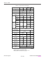
This manual MUST be kept and stored with the aerial platform at all times.

USE THE SERIAL NUMBER OF YOUR MACHINE TO DETERMINE THE CORRECT
OPERATING MANUAL TO USE
MANUAL
PART # 118942AD 122882AJ 122908AE 129908AE 129917AC
(CE)
129918AC
(ANSI/CSA)
129939AA
(AU)
Release Date July 2003 July 2003 July 2003 July 2003 May 2005 May 2005 May 2005
3015 150931 & Below 150932 to 115980
3219 229632 & Below 229633 to 236285 Not Used Not Used
3215 115981 to 152099 152100 to 152169 152170 & Above
3219 Not Used 236286 to 237573 237574 to 239691 239692 & Above 244130 & Above
3220 611286 & Below 611287 to 613550 613551 to 615016 615017 to 615505 615506 & Above 616430 & Above
3226 Not Used 27013 to 28042
28048 to 28117
28043 to 28047
28118 to 270930 270931 to 271776 271777 & Above
4620 66658 & Below 66659 to 66875 66876 to 66889
4626 706174 & Below 706175 to 709362 709363 to 709588
4632 Not Used Not Used
710000 & Above
4830/32 87564 & Below 87565 to 870780 870781 to 871159 Not Used
6826 75578 & Below 75579 to 75618 75619 to 75619 75620 & Above
M
O
D
E
L
S
6832 82573 & Below 82574 to 83066
Not Used
83067 to 83100 83101 & Above
60312AD

Feb. 2004
SKYJACK, Page 3
COMPACTS & CONVENTIONALS
129908AB
IMPORTANT
IMPORTANT indicates a procedure(s) essential for
safe operation and which, if not followed, may
result in a malfunction or damage to the machine.
This Safety Alert Symbol Means Attention!
Become Alert! Your Safety Is Involved.
The Safety Alert Symbol identifies important safety
messages on machines, safety signs in manuals
or elsewhere. When you see this symbol, be alert
to the possibility of personal injury or death. Fol-
low the instructions in the safety message.
DANGER
DANGER indicates an imminently hazardous
situation which, if not avoided, will result in death
or serious injury.
WARNING
WARNING indicates a potentially hazardous
situation which, if not avoided, could result in
death or serious injury.
CAUTION
CAUTION indicates a potentially hazardous
situation which, if not avoided, may result in
minor or moderate injury. It may also be
used to alert against unsafe practices.

COMPACTS & CONVENTIONALS
129908AB
Feb. 2004
SKYJACK, Page 4
Table of Contents
Read and Heed .................................................................................................................................................... 6
Purpose Of Equipment ................................................................................................................................................6
Use Of Equipment .......................................................................................................................................................6
Manual .........................................................................................................................................................................6
Operator ......................................................................................................................................................................6
Optional Accessories...................................................................................................................................................6
Section 1 - About Your Aerial Platform
Scope Of This Manual .................................................................................................................................................7
Warranty Statement .....................................................................................................................................................7
Warranty Procedures ...................................................................................................................................................7
Major Components......................................................................................................................................................9
Major Assemblies ...................................................................................................................................................... 10
Platform ..................................................................................................................................................................... 10
Operator’s Control Box ............................................................................................................................................. 10
Manual Storage Box ..................................................................................................................................................10
Lifting Mechanism ..................................................................................................................................................... 10
Maintenance Support/Safety Bar ............................................................................................................................... 10
Base .......................................................................................................................................................................... 10
Lowering Warning System ......................................................................................................................................... 10
Tilt Sensing System ................................................................................................................................................... 11
The Load Sensing System .........................................................................................................................................11
Serial Number Nameplate ......................................................................................................................................... 11
Standard Features (ANSI, CSA & CE) ........................................................................................................................ 12
Optional Equipment (ANSI, CSA &CE) ......................................................................................................................12
Operator Safety Reminders ....................................................................................................................................... 13
Electrocution Hazard .................................................................................................................................................13
Safety Precautions ..................................................................................................................................................... 14
Section 2 - Operation
General ...................................................................................................................................................................... 17
Operator Qualifications.............................................................................................................................................. 17
Operator’s Responsibility for Maintenance................................................................................................................ 17
Maintenance And Inspection Schedule ..................................................................................................................... 17
Owner’s Inspections ..................................................................................................................................................17
Folding Guardrail System ......................................................................................................................................... 18
Maintenance Support/Safety Bar ............................................................................................................................... 18
Lanyard Attachment Rings ........................................................................................................................................19
Pothole Protection Device ......................................................................................................................................... 19
Tilt Alarm ...................................................................................................................................................................19
Over Load Warning Alarm .........................................................................................................................................20
Base Controls ............................................................................................................................................................ 20
Emergency Main Power Disconnect Switch .............................................................................................................. 20
Base Controls ............................................................................................................................................................ 20
Base Control Box ......................................................................................................................................................21
Base Controls (3215 & 3219) ..................................................................................................................................... 21
Motion Alarm ...........................................................................................................................................................21
Operator’s Control Box ............................................................................................................................................22
Power Extension Deck Control Box .......................................................................................................................... 22

Feb. 2004
SKYJACK, Page 5
COMPACTS & CONVENTIONALS
129908AB
Table of Contents
Section 2 - Continued
Parking Brake ............................................................................................................................................................ 23
Free-Wheeling Valve ..................................................................................................................................................23
Operating Procedures ...............................................................................................................................................24
Set-Up Procedure ...................................................................................................................................................... 24
Raise the Platform ..................................................................................................................................................... 25
Pre-start Inspection....................................................................................................................................................26
Operator’s Checklist .................................................................................................................................................. 26
Start And Operation ..................................................................................................................................................27
Setting the Base Controls .........................................................................................................................................27
Shutdown Procedure .................................................................................................................................................30
Emergency Lowering System .................................................................................................................................... 31
Winching and Towing Procedures .............................................................................................................................32
Preparation After Winching and Towing .....................................................................................................................32
Battery Service Procedure .........................................................................................................................................33
Battery Charging Procedure ......................................................................................................................................33
Battery Charger .........................................................................................................................................................34
Label Locations ......................................................................................................................................................... 42
List of Tables
Table 2-1a, 2-1b. Specifications and Features ...................................................................................................... 36-37
Table 2-2. Floor Loading Pressure ............................................................................................................................. 38
Table 2-3. Owner’s Annual Inspection Record ...........................................................................................................40
Table 2-4. Maximum Platform Capacities (Evenly Distributed) ...................................................................................40
Table 2-5. Maintenance And Inspection Schedule ..................................................................................................... 41

COMPACTS & CONVENTIONALS
129908AB
Feb. 2004
SKYJACK, Page 6
Read and Heed
SKYJACK Inc. is continuously improving and expanding product features on it’s equipment, therefore,
specifications and dimensions are subject to change without notice.
Aerial Platform. A mobile device that has an adjustable position platform supported from ground level
by a structure.
Purpose Of Equipment
The SKYJACK SJIII series aerial platforms are designed to transport and raise personnel, tools and materials to
overhead work areas.
Use Of Equipment
The aerial platform is a highly maneuverable, mobile work station. Lifting and driving MUST be on a flat, level,
compacted surface.
Manual
The operating manual is considered a fundamental part of the aerial platform. It is a very important way to
communicate necessary safety information to users and operators. A complete and legible copy of this
manual must be kept in the provided weather resistant storage compartment on the aerial platform at all
times.
Operator
The operator MUST read and completely understand the safety panel label located on the platform and
ALL other warnings in this manual and on the aerial platform. Compare the labels on the aerial platform
with the labels found within this manual. If any labels are damaged or missing, replace them immediately.
Optional Accessories
The SKYJACK aerial platform is designed to accept a variety of optional accessories. These are listed under
“Standard Features and Optional Equipment”.
Operating instructions for these options (If Equipped) are located in Section 2 of this manual.
For options not listed under “Standard Features and Optional Equipment”, contact the SKYJACK service
department at 800 275-9522 or fax 630 262-0006, include the model and serial number for each applicable
machine.

SKYJACK, Page 7
Feb. 2004
Section 1 - About Your Aerial Platform
COMPACTS & CONVENTIONALS
129908AB
1-1. Scope Of This Manual
a. This manual applies to the ANSI/SIA, CSA and
CE versions of the SJIII, Series aerial platform
models listed on (Table 2-1.)
- Equipment identified with “ANSI” meet the ANSI
SIA-A92.6-1999 standard.
- Equipment identified with “CSA” meets the CSA
B354.2-01 standards.
- Equipment identified with “CE” meets the
requirements for the European countries, i.e.
Machinery Directive 98/37/EEC and EMC Directive
89/336/EEC and the corresponding EN standards.
b. CSA (Canada) and CE (Europe)
Operators are required to conform to national,
state/province and local health and safety
regulations applicable to the operation of this
aerial platform.
c. ANSI/SIA (United States)
Operators are required by the current ANSI/SIA
A92.6 standards to read and understand His/Her
RESPONSIBILITIES in the Manual Of
Responsibilities before they use or operate this
aerial platform.
1-2-a. Warranty Statement
SKYJACK Inc. warrants each new aerial platform to be
free of defective parts and workmanship. During the
first full year, labor and replacement parts will be
provided by the local authorized Skyjack dealer without
charge. For the following 48 months, structural
components found to be defective will be replaced or
repaired at no charge.
A warranty registration card is supplied with each aerial
platform. The warranty is only effective when the warranty
card has been completed and returned to Skyjack within
15 days of invoiced. When aerial platforms are put into
Dealer’s stock, the warranty period does not start until
the aerial platform has been shipped to the dealer’s
customer. When a unit is put into service and no warranty
card has been mailed to Skyjack Inc., the warranty
period will commence 15 days from the date the dealer
was invoiced for the aerial platform.
All warranty claims are subject to approval by Skyjack’s
Service Department. Skyjack Inc. reserves the right to
limit or adjust claims with regard to defective parts, labor
or travel time based on usual and customary guidelines.
Parts purchased from sources other than Skyjack will
not be covered under this warranty. Misuse or improper
operation, lack of normal maintenance and inspections
as outlined in this Operating Manual or the Operating
Maintenance and Parts Manual, alterations to original
design and/or components or accidents will void all
warranty. Batteries or Engines are not covered by this
warranty.
The above mentioned warranty statement is exclusive
and no other warranty whether written, oral or implied
shall apply. Skyjack excludes any implied warranty of
merchantability and fitness and accepts no liability for
consequential damages or for other negligence.
1-2-b. Warranty Procedures
The selling distributor or authorized dealer shall be
responsible for the complete handling of customer
claims under this warranty. Here is what to do:
1. When a customer files a claim under this warranty,
contact Skyjack’s Service Department to verify
warranty coverage. NOTE: The complete serial
number of the aerial platform is required to verify the
claim.
1

Feb. 2004
SKYJACK, Page 8
Section 1 - About Your Aerial Platform
COMPACTS & CONVENTIONALS
129908AB
6. Materials returned for warranty inspection must be:
a. Carefully packaged to prevent additional
damage during shipping.
b. Drained of all contents and all open ports
capped or plugged.
c. Shipped in a container tagged or marked with
the RA number.
d. Shipped PREPAID. Any item(s) returned for
warranty by any other means may be refused
and returned unless prior approval from Skyjack
is obtained.
e. Items shipped to the dealer will be sent freight
prepaid and added to the invoice.
Failure to comply with the above procedures may delay
approval and processing of the warranty claim and could
result in the denial of a warranty claim. Skyjack’s dealer’s
accounts must be kept current in order to approve and
issue warranty credits. Skyjack reserves the right to with-
hold issuance of warranty credits to a dealer if their ac-
count is not in good standing. This is subject to change
without prior notice.
1-2-b. Warranty Procedures (Continued)
2. When Skyjack’s Service Department verifies warranty
coverage, they will also issue an RA (Return
Authorization) number for the return of any defective
component(s). All items over $25.00 USD in value
must be returned to Skyjack Inc.
3. Fill out a Warranty Claim Form from dealer’s supply
of claim forms. Then notify Skyjack’s Service
Department of the warranty claim number on the form
used.
4. The distributor/dealer should then file a warranty claim
with Skyjack Inc. describing the nature of the defect,
probable cause, work performed, travel hours, and labor
hours listed separately. Warranty labor will be paid at
a rate of ($42.00 USD) per hour. The travel allowance
will be paid at the same hourly rate within the dealers
specified territory, limited to a maximum of four (4)
hours. If a part has serviceable components, replace
the faulty component. For instance, if you have a faulty
switch on a controller, please replace the switch.
Hydraulic cylinders should be resealed, unless they
are damaged beyond repair. Engine failures should be
directed to your local engine distributor and covered
by the manufacturers warranty. Skyjack will
accommodate you and your labor. Labor rates and
travel allowances are subject to change without notice.
5. Warranty claims must be received by Skyjack within
15 working days from the date of the repair. Warranty
claims received with insufficient information will be
returned for correction or completion.

SKYJACK, Page 9
Feb. 2004
Section 1 - About Your Aerial Platform
COMPACTS & CONVENTIONALS
129908AB
SKYJACK SJIII Series aerial Platform
Operator’s
Control Box
Manual
Storage Box
Lifting
Mechanism
1-3. Major Components
Extension
Platform
Battery
Tray
Pothole
Protection
Device
Hydraulic/
Electric
Tray
Base
Maintenance
Support
Main
Platform

Feb. 2004
SKYJACK, Page 10
Section 1 - About Your Aerial Platform
COMPACTS & CONVENTIONALS
129908AB
1-4. Major Assemblies
The aerial platform consists of three major assemblies.
The platform, lifting mechanism and the base. An
operator’s control box is mounted on the platform
guardrail. Auxiliary and emergency controls are located
at the base.
1-5. Platform
The platform is constructed of a tubular support frame,
a skid-resistant “diamond plate” deck surface and 39” to
43-1/2" (991 - 1100mm) hinged guardrails with 6"
(152mm) toe boards and mid-rails. The platform can be
entered from the rear through an entry chain or optional
spring-returned gate with latch. The platform is also
equipped with an extension platform.
1-6. Operator’s Control Box
A removable control box, mounted at the front right of
the platform, contains controls for aerial platform motion
and emergency stopping.
1-7. Manual Storage Box
This weather resistant box is mounted to the inside of
the hydraulic cabinet door at the base
or at the front of the platform. It
contains the Operating Manual, the
Operating/Maintenance and Parts
Manual and other important
documentation. The Operating
Manual for this make and model of
aerial platform MUST remain with the
aerial platform and should be stored
in this box.
1-8. Lifting Mechanism
The lifting mechanism is constructed of formed steel or
tube sections making up a scissor-type assembly. The
“scissors” assembly is raised and lowered by single-
acting hydraulic lift cylinders with holding valves. A two-
section pump, driven by an engine or an electric motor,
provides hydraulic power to the lift cylinders.
1-9. Maintenance Support/Safety Bar
A Maintenance Support, located inside the lifting
mechanism (when properly positioned) can support the
scissors and empty platform. The Maintenance Support
MUST be used during inspection and maintenance or
when repairs are being performed within the lifting
mechanism.
1-10. Base
The base is a rigid, one-piece weldment which supports
two side cabinets or two swing out trays.
•Pothole Protection: A mechanically actuated
angle, located under the outside of the trays,
rotates when lifting. This mechanism provides
pothole protection for elevated driving (except
models 6826 and 6832).
•On Models 3215 and 3219: One tray contains
the hydraulic and electrical components. The other
tray contains four (4) 6 volt batteries. The charger
is located at the rear of the machine. The front
axle has two hydraulic motor-driven wheels ,
steerable by a hydraulic cylinder. The rear axle is
fixed and has one spring-applied hydraulically-
released parking brake.
•On Models 3220, 3226, 4620, 4626, 4632, 6826
and 6832: One tray contains the hydraulic and
electrical components. The other tray contains
battery charger and four (4) 6 volt batteries. The
front axle has two non-driven wheels, steerable
by a hydraulic cylinder. The rear axle has two
hydraulic motor-driven wheels and two spring-
applied hydraulically-released parking brakes.
1-11. Lowering Warning System
•(If Equipped) - A lowering warning system
automatically stops the lowering function before
reaching the fully retracted position and sounds
an alarm.

SKYJACK, Page 11
Feb. 2004
Section 1 - About Your Aerial Platform
COMPACTS & CONVENTIONALS
129908AB
1-12. Tilt Sensing System
The tilt sensing system located on the base of the aerial
platform is designed to prevent lifting or driving when
the machine is on a slope greater than a predetermined
limit. If in this situation the platform must be lowered
immediately.
1-13. The Load Sensing System (If Equipped)
The Load Sensing System is a safety device that will
prevent any normal movement of the aerial platform
from a stationary working position after the rated load
is reached and exceeded.
1-14. Serial Number Nameplate
The serial number nameplate, located at the rear of the
machine, list the following:
• Model number
• Serial number
• Machine weight
• Maximum drivable height
• Maximum capacities
• Maximum number of persons permissible on the
platform
• Voltage
• System pressure
• Lift pressure
• Maximum platform height
• Maximum wheel load
• Date manufactured
• Maximum wind speed (CE only)
• Maximum manual force (CE only)
• Maximum incline (CE only)
Use this information for proper operation and mainte-
nance and when ordering service parts.

Feb. 2004
SKYJACK, Page 12
Section 1 - About Your Aerial Platform
COMPACTS & CONVENTIONALS
129908AB
1-15. Standard Features
• Descent Alarm
• Joystick Controller With Proportional Lift and Drive
Functions (See NOTE)
• Swing Out Side Trays
• Dual Spring-Applied, Hydraulically-Released
Parking Brakes
• Manual Lowering System With Electric Holding
Valves On Lift Cylinders
• Operator Horn
• 3 Foot Manual Extension Platform
(32XX and 68XX)
• 4 Foot Manual Extension Platform
(4620 and 4626)
• AC Outlet On Platform
• Lanyard Attachment Rings
• Front Wheel Drive With Tight Turning Radius
(Models 3215 and 3219)
• Hinged Railings
(Except 3215, 3219, 3220 and 4620)
• Tilt Alarm
• Forklift Pockets, Lifting Lugs/Tie Downs
• Hourmeter
• Color-coded, Numbered Wiring System
• Urethane Foam Filled Tires
(Models 6826 and 6832)
• Puncture-Proof Solid Rubber Non-Marking Tires
(All Models Except 6826 and 6832)
• Pothole Protection
(All Models Except 6826 and 6832)
• Movement Alarm (ANSI only)
• Lowering Warning System (CE only)
• Spring-Loaded Half-Height Gate (CE only)
• Scissor Guards (CE only)
(Models 6826 and 6832)
• Overload System (CE only)
1-16. Optional Equipment
• Spring-Loaded Full-Height Gate
• Flashing Amber Light
• 800W AC Generator
• Hydraulically Powered Extension Platform (Except
3215, 3219, 3226 and 4632)
• EE-Rating
• Air Operation Package
(All Models Except 3215 and 3219)
• Shop Air Hose To Platform
• Hinged Railings
(Models 3215, 3219, 3220 and 4620)
• Non -marking, Foam Filled Tires
(6826, 6832 only)
• Propane or Diesel Engine Package
(Consult Skyjack )
• Kit For Power Pack
(Consult Skyjack )
• Spring-Loaded Half-Height Gate (ANSI only)
• Scissor Guards (ANSI only)
(Models 6826 and 6832)
• Lowering warning system (ANSI only)
• Movement Alarm (CE only)
• Overload System (ANSI only)
Note: Platform lowering and steering are not proportional.

SKYJACK, Page 13
Feb. 2004
Section 1 - About Your Aerial Platform
COMPACTS & CONVENTIONALS
129908AB
1-17. Operator Safety Reminders
The National Safety Council reminds us that most accidents are caused by the failure of some individuals to follow
simple and fundamental safety rules and precautions. Common sense dictates the use of protective clothing when
working on or near machinery. Use appropriate safety devices to protect your eyes, ears, hands, feet and body.
You, as a careful operator, are the best insurance against an accident. Therefore, proper usage of this aerial platform
is mandatory. The following pages of this manual should be read and understood completely before operating the
aerial platform.
Any modifications from the original design are strictly forbidden without written permission from SKYJACK Inc.
1-18. Electrocution Hazard
This aerial platform is not electrically insulated. Maintain a minimum safe approach distance (MSAD) from
energized power lines and parts as listed below. Operator must allow for platform sway, rock or sag. This aerial
platform does not provide protection from contact with or proximity to an electrically charged conductor.
DO NOT USE THE MACHINE AS A GROUND FOR WELDING.
DO NOT OPERATE THE MACHINE DURING LIGHTNING OR STORMS.
Failure to comply with your required responsibilities in the use and operation of the aerial platform could
result in death or serious injury!
Warning
DANGER
Avoid Power Lines
Minimum Safe Approach Distance
ANSI/SIA A92.6-1999 &
CSA B354.2-01 Requirements
CE Guidance Note
“Avoidance of danger from Overhead Lines”
Voltage Range Minimum Safe Approach Distance
(Phase to Phase) Feet Meters
0 To 300V Avoid Contact
Over 300V to 50KV 10 3.05
Over 50KV to 200KV 15 4.60
Over 200KV to 350KV 20 6.10
Over 350KV to 500KV 25 7.62
Over 500KV to 750KV 35 10.67
Over 750KV to 1000KV 45 13.72
Adhere strictly to the governmental rulings and
regulations applicable in your country.
FAILURE TO AVOID THIS HAZARD WILL RESULT IN DEATH OR SERIOUS INJURY!
60023AC

Feb. 2004
SKYJACK, Page 14
Section 1 - About Your Aerial Platform
COMPACTS & CONVENTIONALS
129908AB
•DO NOT increase the lateral sur-
face area of the platform. In-
creasing the area exposed to the
wind will decrease machine sta-
bility.
•DO NOT drive or elevate the
aerial platform if it is not on firm
level surfaces. Do not drive el-
evated near depressions or holes
of any type, loading docks, de-
bris, drop-offs and surfaces that
may affect the stability of the
aerial platform.
•If Operation In Areas With
Holes Or Drop-offs Is Abso-
lutely Necessary, elevated driv-
ing shall not be allowed. Posi-
tion the aerial platform horizon-
tally only with the platform fully
lowered. After ensuring that all 4
wheels or outriggers have con-
tact with level firm surface, the
aerial platform can be elevated.
After elevation, the drive function
must not be activated.
•Elevated driving must only be
done on a firm level surface.
•DO NOT Ascend or descend a
grade steeper than 23% (3215,
3219), or 25% (3220, 3226, 4620,
4626, 4632, 6826 & 6832). As-
cend or descend grades only
when fully lowered and then only
to the maximums noted above.
Warning
Failure to heed the following safety precautions could
result in tip over, falling, crushing, or other hazards
leading to death or serious injury
•KNOW all Federal, State, Provincial and local rules
which apply to your MACHINE and JOBSITE.
•DO NOT leave the aerial platform unattended with
the key in the key switch.
•WEAR all the protective clothing and personal
safety devices issued to you or called for by job
conditions.
•DO NOT wear loose clothing,
dangling neckties, scarves,
rings, wristwatches or other jew-
elry while operating this lift.
•AVOID entanglement with
ropes, cords or hoses.
•AVOID falling. Stay within the
boundaries of the guardrails.
•DO NOT raise the aerial platform
in windy or gusty conditions.
1-19. Safety Precautions
Know And Understand The Safety Precautions Before Going On To Next Section.

SKYJACK, Page 15
Feb. 2004
Section 1 - About Your Aerial Platform
COMPACTS & CONVENTIONALS
129908AB
1-19. Safety Precautions (Continued)
Know And Understand The Safety Precautions Before Going On To Next Section.
•DO NOT raise the aerial platform
while the machine is on a truck,
fork lift or other device or vehicle.
•BE AWARE of crushing hazards.
Keep all body parts inside plat-
form guardrail.
•DO NOT lower the platform un-
less the area below is clear of
personnel and obstructions.
•ENSURE that there are no personnel or obstruc-
tions in the path of travel, including blind spots.
•BE AWARE of blind spots when operating the aerial
platform.
•STUNT driving and horseplay are prohibited.
•ENSURE ALL tires are in good condition and lug
nuts are properly tightened.
•DO NOT alter or disable limit switches or other
safety devices.
•DO NOT use the aerial platform without guard-
rails, lock pins and the entry gate/chain/bar in
place.
•DO NOT exceed the rated capacity of the aerial
platform. Do make sure the load is evenly distrib-
uted on the platform.
•DO NOT operate on surfaces not capable of hold-
ing the weight of the aerial platform including the
rated load, e.g. covers, drains, and trenches.
•DO NOT operate an aerial plat-
form that has ladders, scaffold-
ing or other devices mounted on
it to increase its size or work
height. It is prohibited.
•DO NOT exert side forces on
aerial platform while elevated.
•DO NOT use the aerial platform
as a crane. It is prohibited.
•DO NOT sit, stand or climb on
the guardrails. It is prohibited.
•DO NOT climb on scissor arm
assembly. It is prohibited.
•BE AWARE of overhead obstruc-
tions or other possible hazards
around the aerial platform when
driving or lifting.

Feb. 2004
SKYJACK, Page 16
Section 1 - About Your Aerial Platform
COMPACTS & CONVENTIONALS
129908AB
•DO NOT overload the platform, the lift relief valve
does not protect against overloading when the
platform is elevated.
•DO NOT attempt to free a snagged platform with
lower controls until personnel are removed from
the platform.
•DO NOT position the aerial platform against an-
other object to steady the platform.
Warning
Entering and Exiting the aerial platform should only
be done using the 3 point contact system.
• Use only equipped access openings and ladders.
• Enter and exit only when the elevating aerial
platform is in the fully retracted position
•Do Use Three Point Contact To Enter And Exit
The Platform. Enter and exit the platform from the
ground only. Face the machine when entering or
exiting the platform.
•Three Point Contact means that two hands and
one foot OR one hand and two feet are in contact
with the aerial platform at all times during entering
and exiting.
Warning
An operator should not use any aerial platform
that :
• Does not have a clean, uncluttered work area.
• Does not appear to be working properly.
• Has been damaged or appears to have worn or
missing parts.
• Has alterations or modifications not approved by
the manufacturer.
• Has safety devices which have been altered or
disabled.
Failure to avoid these hazards could result in
death or serious injury.
1-19. Safety Precautions (Continued)
Know And Understand The Safety Precautions Before Going On To Next Section.
Jobsite Inspection.
• Do not use in hazardous locations.
• Perform a thorough jobsite inspection prior to
operating the aerial platform, to identify potential
hazards in your work area.
• Be aware of moving equipment in the area. Take
appropriate actions to avoid collision.

SKYJACK, Page 17
Section 2 - Operation
Feb. 2004
COMPACTS & CONVENTIONALS
129908AB
2
2-1. General
This section provides the necessary information needed
to operate the aerial platform. The following descrip-
tions are for identification, explanation and locating
purposes only. It is important that the user reads and
understands the proper procedures before operating
the aerial platform.
2-2. Operator Qualifications
•ONLY trained and authorized personnel MUST
be permitted to operate an aerial platform.
• Safe use of this aerial platform requires the
operator to understand the limitations and
warnings, operating procedures and operator’s
responsibility for maintenance. Accordingly, the
operator MUST understand and be familiar with
this operating manual, its warnings and
instructions, Manual of Responsibilities and ALL
warnings and instructions on the aerial
platform.
• The operator MUST be familiar with employer’s
work rules and related government regulations
and be able to demonstrate their ability to
understand and operate THIS make and model
of aerial platform in the presence of a qualified
person.
2-3. Operator’s Responsibility for
Maintenance
Warning
Competent personnel who are familiar with mechani-
cal procedures must perform inspection and mainte-
nance.
Death or serious injury could result from the use of an
aerial platform that is not properly maintained or kept
in good working order.
• The operator must be sure that the aerial platform
has been properly maintained and inspected
before using it.
• The operator must perform ALL the daily
inspections found in “Table 2-5”, even if the
operator is not directly responsible for the
maintenance of this aerial platform.
2-4. Maintenance And Inspection
Schedule
• The inspection points covered in “Table 2-5”
indicate the areas of the aerial platform to be
maintained or inspected and at what intervals
the maintenance and inspections are to be
performed.
• The actual operating environment of the aerial
platform may affect the maintenance schedule.
Warning
Use original or equivalent to the original parts and
components for the aerial platform.
2-5. Owner’s Inspections
It is the responsibility of the owner to arrange daily,
weekly, monthly and annual inspections of the aerial
platform. Refer to “Table 2-5” for recommended main-
tenance and inspection areas and intervals. A record of
annual inspection is kept on a label located on the scis-
sors assembly. Refer to “Table 2-3” in this manual.

Feb. 2004
SKYJACK, Page 18
Section 2 - Operation
COMPACTS & CONVENTIONALS
129908AB
2-6. Folding Guardrail System
Fold-Down Guardrail System - This system, when
folded down, reduces the retracted height of the aerial
platform for transporting and traveling through
doorways only.
Figure 2-1. Fold-Down Guardrail System
1. Guardrail Locking Pin With Lanyard - To fold
the guardrail system down, remove the locking
pin at each pivot point and lower each guardrail.
To raise the guardrail system, swing up each
guardrail and lock in place with the locking pins
ensuring that the detent ball of each pin is all the
way through and clear of the side of the pivot
brackets. (Refer to “Figure 2-1”)
Warning
Before operating this aerial platform
check the guardrail system for loose or missing
locking pins. The guardrail system must be upright
and all pins must be locked in place. Death or serious
injury could result if the guardrail system is not
upright or properly locked.
DETENT BALL
CLEAR OF SIDE
OF PIVOT BRACKET
Correct Position Of Locking Pin
1
2-7. Maintenance Support/ Safety Bar
Maintenance Support - The maintenance support is
designed to support the scissors assembly. When prop-
erly positioned it can support the scissors and empty
platform. The Maintenance Support MUST be used
when inspection and maintenance or repairs are to be
performed within the lifting mechanism.
Figure 2-2. Maintenance Support/ Safety Bar
Warning
The maintenance support must be used when inspec-
tion and maintenance or repairs are to be performed
within the lifting mechanism.
Failure to use this safety mechanism could result
in death or serious injury.
Proper Use Of Maintenance Support/Safety Bar
•Remove all material from platform.
•Raise platform until there is adequate clearance
to swing down the maintenance support.
•Swing maintenance support down from stor-
age bracket into a vertical position.
•Remove hands and arms from scissors area.
•Lower platform until bottom end of maintenance
support contacts the labeled cross bar and
scissors are supported by maintenance sup-
port .
•Turn off Emergency Main Power Disconnect Switch.
To Store Back The Maintenance Support/Safety Bar
•Turn on Emergency Main Power Disconnect
Switch.
•Raise platform until there is adequate clearance
to swing up the maintenance support.
•Swing bar up into storage bracket.
•Lower platform.
The scissors must be fully lowered before raising
or lowering the guardrails.
Warning

SKYJACK, Page 19
Section 2 - Operation
Feb. 2004
COMPACTS & CONVENTIONALS
129908AB
Warning
Crushing Hazard
Personnel on ground MUST stay clear of pothole
protection bar.
Warning
Do not drive elevated in areas where electrical cords
or debris are in the path of travel.
Maintenance of the Pothole Protection Device:
• As with all safety devices, periodic inspection and
maintenance is required to ensure the proper
operation of the pothole protection device. This
mechanism is designed to reduce ground
clearance and assist in the stability of an elevated
aerial platform in the event the machine encounters
a “Drop-off” or “Pothole”. The nature of this safety
feature relies on maintaining a consistent ground
clearance, therefore if the machine ever does come
to rest on the Pothole device, the platform should
be immediately lowered and “locked out” to
prevent further use until a complete inspection of
the mechanism is performed by a qualified
technician.
2-10. Tilt Alarm
• The aerial platform is equipped with a device,
which senses when the machine is out of level in
any direction. When activated, it prevents Drive
and Lift functions of the aerial platform and an
alarm produces an audible sound accompanied
by the amber light (If Equipped). These alarms
activate once every 1.5 seconds. Lower platform
completely, then reposition machine so that it is
level before raising platform.
Warning
Do not reach through the scissors assembly when the
platform is raised without the maintenance support
properly positioned. Failure to avoid this hazard will
result in death or serious injury.
2-8. Lanyard Attachment Ring (If Equipped)
Lanyard Attachment Ring - Use this ring as an attach-
ment point for safety harness tethers. DO NOT attach
harnesses to any other point on the platform. DO NOT
use this ring to lift, anchor, secure or support the plat-
form or any other apparatus or material.
Figure 2-3. Lanyard Attachment Ring
Warning
The lanyard attachment ring is used for travel re-
straint, within the limits of the platform only. It is not
a fall arresting device! Use as such could result in
death or serious injury.
2-9. Pothole Protection Device
Figure 2-4. Pothole Protection Device
1. Pothole Protection Device - This device consists
of a mechanically actuated steel weldments,
located under the hydraulic/electric tray and
battery tray, these weldments will automatically
rotate for reduced ground clearance when
elevating the aerial platform. If the pothole
protection device has not fully lowered, the drive
function will be disabled.
1
1
1

Feb. 2004
SKYJACK, Page 20
Section 2 - Operation
COMPACTS & CONVENTIONALS
129908AB
2-11. Overload Warning Alarm (If Equipped)
• The aerial platform is equipped with a load sensing
system. A rapidly flashing red light at the
operator’s controls will activate at loads just less
than rated load (90%).
An audible alarm will sound for approximately 2
seconds, 5 times per minute at rated load exactly.
If the machine becomes overloaded, the flashing
light and audible alarm continue and all electrically
controlled machine movement functions stop. To
resume normal operation, remove the overload
from the platform.
• If the machine during the operation comes in
contact with an overhead obstruction the platform
could become overloaded and all functions would
stop. Release of the platform from this situation
can only be effected by use of the Emergency
Lowering System. Refer to “section 2-24”
Note
After reaching full extension and upon lowering, the
machine could stop and take an overload reading, re-
turn the joystick to the neutral center position, and re-
lease the Enable trigger switch. If the machine is over-
loaded, the flashing light and audible alarm continue
and all electrically controlled machine movement func-
tions stop. To resume normal operation, remove the
overload from the platform.
2-12. Base Controls
2-12-a. Emergency Main Power Disconnect Switch
Emergency Main Power Disconnect Switch - This
Switch is located at the rear of the base.
Figure 2-5. Emergency Main Power Disconnect Switch
1. Emergency Main Power Disconnect Switch -
This Switch, when in “OFF” position, disconnects
power to all circuits. Switch MUST be in “ON”
position to operate any circuit.
2-12-b. Base Controls (If Equipped)
This control station is located in the Hydraulic/Electric
tray. It contains the following controls:
Figure 2-6. Electrical Panel
1. Buzzer Alarm - This audible pulse alarm will beep
in varying intervals depending on the status of the
platform.
2. Platform Up/Down Toggle Switch - This toggle
type switch raises or lowers the platform to a
desired height.(If Equipped)
3. Hourmeter - This gauge records the accumulated
time of operation of the aerial platform.
4. Circuit Breaker Resets - In the event of a power
overload or positive circuit grounding, the circuit
breaker will pop out.
1 32 4
1
Page is loading ...
Page is loading ...
Page is loading ...
Page is loading ...
Page is loading ...
Page is loading ...
Page is loading ...
Page is loading ...
Page is loading ...
Page is loading ...
Page is loading ...
Page is loading ...
Page is loading ...
Page is loading ...
Page is loading ...
Page is loading ...
Page is loading ...
Page is loading ...
Page is loading ...
Page is loading ...
Page is loading ...
Page is loading ...
Page is loading ...
Page is loading ...
Page is loading ...
Page is loading ...
Page is loading ...
Page is loading ...
Page is loading ...
Page is loading ...
-
 1
1
-
 2
2
-
 3
3
-
 4
4
-
 5
5
-
 6
6
-
 7
7
-
 8
8
-
 9
9
-
 10
10
-
 11
11
-
 12
12
-
 13
13
-
 14
14
-
 15
15
-
 16
16
-
 17
17
-
 18
18
-
 19
19
-
 20
20
-
 21
21
-
 22
22
-
 23
23
-
 24
24
-
 25
25
-
 26
26
-
 27
27
-
 28
28
-
 29
29
-
 30
30
-
 31
31
-
 32
32
-
 33
33
-
 34
34
-
 35
35
-
 36
36
-
 37
37
-
 38
38
-
 39
39
-
 40
40
-
 41
41
-
 42
42
-
 43
43
-
 44
44
-
 45
45
-
 46
46
-
 47
47
-
 48
48
-
 49
49
-
 50
50


Skyjack SJIII 3215 Operating instructions
- Category
- Floor Machine
- Type
- Operating instructions
- This manual is also suitable for
Ask a question and I''ll find the answer in the document
Finding information in a document is now easier with AI
Related papers
-
Skyjack SJIII 3219 Parts Manual
-
-
-
-
-
-
-
-
-
Other documents
-
 Oshkosh JLG X33JP Service And Maintenance Manual
-
JLG 660SJ Operation And Safety Manual
-
 Oshkosh Corporation JLG 660SJC Operation And Safety Manual
-
 TK MCS-1 Operator's Safety And Service Manual
-
JLG 450A Service And Maintenance Manual
-
Mec 1930SE Slim - A92.6 Operating instructions
-
 Bomag BT 65 Operating Instructions, Maintenance Instructions
-
-
-


