Page is loading ...

Instruction
Manual
Multicomponent Force
Plate for Biomechanics
Type 9281E…
ä
9281E_002-463e-10.08

Instruction
Manual
Multicomponent
Force Plate for
Biomechanics
Type 9281E…
ä
9281E_002-463e-10.08
Multicomponent Force
Plate for Biomechanics
Type 9281E…
ä


Foreword
9281E_002-463e-10.08 Page 1
Foreword
Information in this document is subject to change without
notice. Kistler reserves the right to change or improve its
products and make changes in the content without obliga-
tion to notify any person or organization of such changes
or improvements.
© 2008 Kistler Group. All rights reserved. Except as ex-
pressly provided herein, no part of this manual may be re-
produced for any purpose without the express prior written
consent of Kistler Group.
Kistler Group
Eulachstrasse 22
8408 Winterthur
Switzerland
Tel. +41 52 224 11 11
Fax +41 52 224 14 14
www.kistler.com

Multicomponent Force Plate for Biomechanics Type 9281E…
Page 2 9281E_002-463e-10.08
Content
1. Introduction ................................................................................................................................... 4
2. Important Information.................................................................................................................... 5
2.1 For your Safety..................................................................................................................... 5
2.2 ä-Conformity.....................................................................................................................6
2.3 How to Treat the Instrument................................................................................................ 6
2.3.1 With External Amplifier (Type 9281E) .................................................................................. 6
2.4 Hints for Using the Operating Instructions ........................................................................... 7
2.5 What Happens After Modifications? .................................................................................... 7
2.6 Disposal Instructions for Electrical and Electronic Equipment ................................................ 7
3. General Description of the Instrument ...........................................................................................8
3.1 What does a Multicomponent Force Plate Do? .................................................................... 8
3.2 Two Different Versions......................................................................................................... 9
3.3 Application Examples ........................................................................................................... 9
3.4 Functional Principle .............................................................................................................. 9
3.5 Design of the Force Plate ................................................................................................... 11
4. Assembly, Installation and Putting Into Operation...................................................................... 12
4.1 Important Remarks............................................................................................................. 12
4.2 Basic Circuitry and Cabling of the Measuring System ......................................................... 13
4.3 Connections with External Amplifier (Type 9281E)............................................................. 14
4.3.1 Output Connector of Force Plate Type 9281E.................................................................... 14
4.4 Connections with Built-In Amplifier (Type 9281EA) ........................................................... 15
4.4.1 Output Connector of Force Plate Type 9281EA (with Built-In Amplifier)............................ 16
4.4.2 Cable Type 1759A... .......................................................................................................... 17
4.4.3 Digital Control.................................................................................................................... 18
5. Operation..................................................................................................................................... 19
5.1 Range Selection.................................................................................................................. 19
5.2 Operate/Reset ...................................................................................................................19
5.2.1 Balance (Posturography) .................................................................................................... 20
5.3 Time Constant.................................................................................................................... 20
5.4 Usable Frequency Range.................................................................................................... 20
5.5 Temperature Influences...................................................................................................... 21
5.6 Polarity of the Measuring Signal......................................................................................... 21
5.6.1 x- and y-Directions.............................................................................................................21
5.6.2 z-Direction ......................................................................................................................... 21
5.7 Surface Pressure ................................................................................................................. 22
6. Maintenance ................................................................................................................................ 23
6.1 Recalibration of the Instrument .......................................................................................... 23
6.2 Weekly Function Check...................................................................................................... 23
6.2.1 Drift Check......................................................................................................................... 23
6.2.2 Check Gap Around Force Plate........................................................................................... 24
6.2.3 System Check..................................................................................................................... 24
6.2.4 Setup Parameters ............................................................................................................... 24
6.3 Regular Calibration of the Charge Amplifier ....................................................................... 25

Content
9281E_002-463e-10.08 Page 3
6.4 Calibration of the Force Plate..............................................................................................25
6.5 Regular Checks ...................................................................................................................26
6.5.1 With External Amplifier (Type 9281E) .................................................................................26
6.6 Cleaning and Sterilization....................................................................................................27
7. Trouble Shooting ..........................................................................................................................28
7.1 Defective Force Plate ..........................................................................................................28
8. Technical Data ..............................................................................................................................29
8.1 Dimensions .........................................................................................................................29
8.2 Specifications for Type 9281E .............................................................................................30
8.2.1 Mechanical and Environment..............................................................................................31
8.2.2 Electrical..............................................................................................................................31
8.3 Specifications for Type 9281EA...........................................................................................32
8.3.1 General 32
8.3.2 Mechanical and Environment..............................................................................................33
8.3.3 Electrical..............................................................................................................................33
8.3.4 Built-In 8 Channel Charge Amplifier....................................................................................34
8.4 Center of Pressure COP Accuracy .......................................................................................35
8.4.1 Error Δax............................................................................................................................35
8.4.2 Error Δay............................................................................................................................35
8.4.3 COP Correction Algorithm for Force Plates.........................................................................36
8.5 Frequency Response ..........................................................................................................37
9. Glossary........................................................................................................................................38
9.1 Coordinate System..............................................................................................................38
9.1.1 Kistler Coordinate System ...................................................................................................38
9.1.2 ISB Coordinate System........................................................................................................39
9.2 Parameters Calculation........................................................................................................39
10. Warranty.......................................................................................................................................40
11. Declaration of Conformity ............................................................................................................41
Total Pages 42

Multicomponent Force Plate for Biomechanics Type 9281E…
Page 4 9281E_002-463e-10.08
1. Introduction
Please take the time to thoroughly read this instruction
manual. It will help you with the installation, maintenance,
and use of this product.
Kistler offers a wide range of products for use in measuring
technology:
Piezoelectric sensors for measuring force, torque, strain,
pressure, acceleration, shock, vibration and acoustic-
emission
Strain gage sensor systems for measuring force and
moment
Piezoresistive pressure sensors and transmitters
Signal conditioners, indicators and calibrators
Electronic control and monitoring systems as well as
software for specific measurement applications
Data transmission modules (telemetry)
Kistler also develops and produces measuring solutions for
the application fields engines, vehicles, manufacturing,
plastics and biomechanics sectors.
Our product and application brochures will provide you
with an overview of our product range. Detailed data
sheets are available for almost all products.
If you need additional help beyond what can be found ei-
ther on-line or in this manual, please contact Kistler's ex-
tensive support organization.

Important Information
9281E_002-463e-10.08 Page 5
2. Important Information
Please keep to the following rules without fail. This will en-
sure your personal safety when working, and assure long,
trouble-free performance by the instrument.
2.1 For your Safety
This instrument has been tested thoroughly and it left
the works in a perfectly safe condition. To maintain this
condition and assure safe operation, the user must ob-
serve the directives and warnings contained in these in-
structions
The force plate must be installed, operated and main-
tained only by persons who are familiar with it and
adequately qualified for their particular tasks
When it must be assumed that safe operation is no
longer possible, the instrument must be taken out of
operation and secured against unintentional use
It must be assumed that safe operation is no longer possi-
ble if:
The instrument is visibly damaged
It no longer functions
It has been in lengthy storage under adverse conditions
It has received rough treatment during transport
Please mount the force plate on its foundation following
the instructions in chapter 4 "Assembly, installation and
putting into operation".
According to safety requirements the following has to be
observed:
The force plate has to be connected to earth using the Po-
tential Equalization Conductor provided in the scope of de-
livery to meet the ä-standards regarding Earth Leakage
Current.
The data acquisition computer and persons who are in di-
rect contact with it have to remain in a distance of 1,5 m
from the patient at all times for the same reason.

Multicomponent Force Plate for Biomechanics Type 9281E…
Page 6 9281E_002-463e-10.08
2.2 ä-Conformity
The Force Plate Type 9281E… is conforming to ä direc-
tives according to the Declaration of Conformity enclosed
with this operating instructions.
2.3 How to Treat the Instrument
The force plate may be used only under the specified
environmental and operating conditions
Protect the signal output against dirt and do not touch
it with your fingers. When the connection is not being
used, cover it with the cap provided
When the force plate is not in use, protect it by keeping
it in the packing case supplied
When performing long-time measurements, make sure
that the temperature of the force plate remains as con-
stant as possible
2.3.1 With External Amplifier (Type 9281E)
The insulation resistance is crucially important with pie-
zoelectric measurements. It must be around 1014 Ω (but
at least 1013 Ω)
To obtain this resistance, all plug and socket connec-
tions must be kept meticulously clean and dry
The insulation resistance can be measured with the in-
sulation tester Type 5493
The connecting cable from force plate to charge ampli-
fier is highly insulating. Use only the proper cable
Do not remove the connecting cable from the force
plate

Important Information
9281E_002-463e-10.08 Page 7
2.4 Hints for Using the Operating Instructions
We recommend reading the entire Operating Instructions
as a matter of principle. If you're in a hurry, however, and
you've already gathered experience with Kistler force
plates, you can confine your reading to the information
that you really need.
We have endeavoured to arrange these instructions so that
you can find the information you need without difficulty.
Please keep these Operating Instructions in a safe place
where they can be consulted any time.
If the instructions get lost, just turn to your Kistler distribu-
tor and they will be replaced without delay.
All information and directives in these instructions may be
modified at any time without prior notification.
2.5 What Happens After Modifications?
Modifications to instruments result in alterations of the op-
erating instructions as a rule. In such cases, enquire at your
Kistler distributor about the possibilities of updating your
documentation.
2.6 Disposal Instructions for Electrical and Electronic Equipment
Do not discard old electronic instruments in municipal
trash. For disposal at end of life, please return this prod-
uct to an authorized local electronic waste disposal ser-
vice or contact the nearest Kistler Instrument sales office
for return instructions.

Multicomponent Force Plate for Biomechanics Type 9281E…
Page 8 9281E_002-463e-10.08
3. General Description of the Instrument
3.1 What does a Multicomponent Force Plate Do?
The multicomponent force plate provides dynamic and
quasi-static measurement of the 3 orthogonal components
of a force (Fx, Fy, Fz) acting from any direction on the top
plate.
With the aid of optional evaluation devices (e.g. software
system BioWare) the following quantities can also be
measured:
The moments Mx, My and Mz.
The coordinates ax and ay of the point of application of
force on the force plate surface COP = Center of Pres-
sure
The torque Tz (free moment) about an axis normal to
the force plate surface
Center of mass displacement and acceleration, physical
power and work, coefficient of friction
The multicomponent force plate distinguishes itself espe-
cially by the following features:
Wide measuring and frequency range
Light weight
High overload capacity
Corrosion resistant design, protected against
splashing water
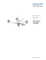
Fig. 1: Multicomponent force plate for biomechanics
Type 9281E...

General Description of the Instrument
9281E_002-463e-10.08 Page 9
3.2 Two Different Versions
The force plate Type 9281E... is available in two versions:
9281E with external 8 channel amplifier
(e.g. Type 9865…)
9281EA with built-in amplifier
3.3 Application Examples
The force plate is particularly suitable to measure fast
actions and impact in sports but it can also be used for
a wide range of other applications
Biomechanical investigations, e.g. recording the forces
exerted by the human foot when standing, walking or
running (gait analysis)
Orthopedic examinations
Determining progress in rehabilitation, e.g. with pros-
thesis, after fractures etc.
Analysis of high dynamic sports activities to optimize
training and for competition analysis (e.g. starting and
takeoff behaviour, performance measurement etc.)
Coefficients of friction can be determined dynamically
and statically with the BioWare software system
3.4 Functional Principle
The force to be measured is introduced via a top plate and
distributed between four 3-component force sensors ar-
ranged between mounting base and top plate.
Each of the sensors has three pairs of quartz plates, one
sensitive to pressure in the z-direction and the other two to
shear in the x- and y-directions respectively. The measure-
ment is virtually without displacement.

Multicomponent Force Plate for Biomechanics Type 9281E…
Page 10 9281E_002-463e-10.08
In these four force sensors the force introduced is resolved
into three components.
Fig. 2: 3-component force sensor
The electrical charges yielded by the force plate are strictly
proportional to the measured quantities. They are con-
verted by charge amplifiers into analog voltages and can
then be processed in any way.
Negative charges give positive voltages at the output of
the charge amplifier, and vice versa.
Out of the 12 output signals of the 4 sensors, 2 each of the
shear forces which have the same line of action can be
paralleled (e.g. Fx1 and Fx2 to obtain Fx1+2, etc.). Therefore,
only 8 signals are needed for further processing.
Fig. 3: Force plate output signals

General Description of the Instrument
9281E_002-463e-10.08 Page 11
3.5 Design of the Force Plate
The force plate comprises a top plate of sandwich light-
weight construction under which the four 3-component
force sensors are mounted under high prestress.
This prestress is a prerequisite for transmissing shear forces
by friction.
Fig. 4: Cross section through force plate
1 3-component force sensor
2 Prestressing elements (hollow screw)
3 Cabling
4 Top plate of sandwich lightweight construction
5 Top cover with O-ring
6 Fastening screw M12x25
7 Mounting frame Type 9423
The four prestressing elements are at the same time the
feet upon which the force plate rests and with which it is
screwed down onto the mounting frame.
The force plate is corrosion-resistant and proof against
splashing water (degree of protection IP65).

Multicomponent Force Plate for Biomechanics Type 9281E…
Page 12 9281E_002-463e-10.08
4. Assembly, Installation and Putting Into Operation
4.1 Important Remarks
The multicomponent force plate Type 9281E... is a preci-
sion instrument, however its inherent accuracy can only be
exploited and retained if it is treated carefully. The follow-
ing points should be observed:
Never drop the force plate or expose it to heavy im-
pacts! The maximum force of a shock of this kind could
exceed the measuring range of the instrument and
cause damage
For safety reasons the force plate has to be grounded
using a separate ground wire connected to the M4
thread near the platform connector
Observe that the surface pressure is limited to max.
5 N/mm2. (Details see technical data)
The force plate should be installed only by persons suf-
ficiently qualified for this job
For the force plate 9281E... the mounting frame 9423 is
available for correct mounting on a concrete base
Basically the mounting frame is grouted onto the con-
crete base using castable grout. Then the force plate is
screwed onto the mounting frame, with a gap separat-
ing the top plate from the surrounding structure
Please refer to the operating instructions 002-034 "Force
Plate Installation an Maintenance" for detailed procedures
and information.
For nonobservance of the mounting instructions Kistler will
decline all responsibility.

Assembly, Installation and Putting Into Operation
9281E_002-463e-10.08 Page 13
4.2 Basic Circuitry and Cabling of the Measuring System
The electric charges (in pC) yielded by the force plate are
converted by charge amplifiers into proportional voltages,
which in turn can be displayed, recorded or further proc-
essed using appropriate equipment.
The following rules should be observed when cabling the
measuring rig:
Between force plate and charge amplifier the special
cables supplied by Kistler must be used
Ordinary cables may be used to link the charge amplifi-
ers with the display or evaluation instruments
Make sure that all work with electrical connections is
done carefully and with cleanliness. Remove the protec-
tive caps from the connections only immediately before
connecting a cable
According to safety requirements the following has to be
observed:
The force plate has to be connected to earth using the Po-
tential Equalization Conductor provided in the scope of de-
livery to meet the ä-standards regarding Earth Leakage
Current.
The data acquisition computer and persons who are in di-
rect contact with it have to remain in a distance of 1,5 m
from the patient at all times for the same reason.

Multicomponent Force Plate for Biomechanics Type 9281E…
Page 14 9281E_002-463e-10.08
4.3 Connections with External Amplifier (Type 9281E)
The following figure shows the elements required for a
complete measuring system.
Fig. 5: Example of a complete measuring system
Measuring system with BioWare and two force plates Type
9281E.
Instead of the BioWare software system also other process-
ing and indicating instruments can be connected to the
charge amplifier.
4.3.1 Output Connector of Force Plate Type 9281E
1 Ground
2 Fx1+2
3 Fx3+4
4 Fy1+4
5 Fy2+3
6 Fz1
7 Fz2
8 Fz3
9 Fz4
Fig. 6: Fischer 9 pin negative
Socket type: 9 pin Fischer DEE 104A055
Important Remarks:
It is very important that the correct type of cable be used
only
If the contacts or insulating material are contaminated,
they can be cleaned with cleaning spray (Type 1003) or
clean white gasoline (rectified benzene). The insulation
resistance >10 TΩ can be measured using an insulation
measuring instrument (Type 5493). Please contact our
agent for support

Assembly, Installation and Putting Into Operation
9281E_002-463e-10.08 Page 15
4.4 Connections with Built-In Amplifier (Type 9281EA)
The following figure shows the elements required for a
complete measuring system
Fig. 7: Example of a complete measuring system
Measuring system with BioWare and two force plates Type
9281EA.
Instead of the BioWare software system also other process-
ing and indicating instruments can be connect to the force
plate. A control unit Type 5233A2 is available for power
supply and remote controlling.
Fig. 8: Measuring system with one force plate and control
unit Type 5233A2

Multicomponent Force Plate for Biomechanics Type 9281E…
Page 16 9281E_002-463e-10.08
4.4.1 Output Connector of Force Plate Type 9281EA (with Built-In Amplifier)
1 Exct. GND
2 Fz4
3 Fz3
4 Fz2
5 Fz1
6 Operate
7 Control GND
8 N.C. (reserved)
9 Fx1+2
10 Fx3+4
11 Fy1+4
12 Fy2+3
13 A’ (Range z select)
14 Signal GND
15 N.C. (reserved)
16 A (Range x, y select)
Fig. 9: Fischer 19 pin negative 17 B (Range x, y select)
18 B’ (Range z select)
19 Excitation +10 … +30 VDC
Socket type: 19 pin Fischer DEE 104A092-130
Front view

Assembly, Installation and Putting Into Operation
9281E_002-463e-10.08 Page 17
4.4.2 Cable Type 1759A...
A cable Type 1759A... (90 degree Fischer connector) is
available from the force plate Fischer 19 pin connector to a
D-Sub 37 pin neg. connector. It provides the following
output connector and is compatible with the Kistler
BioWare hardware.
Signal GND 19 37 Fx12
Signal GND 18 36 Fx34
Signal GND 17 35 Fy14
Signal GND 16 34 Fy23
Signal GND 15 33 Fz1
Signal GND 14 32 Fz2
Signal GND 13 31 Fz3
Signal GND 12 30 Fz4
Signal GND 11 29 Control GND
NC 10 28 Control GND
A’ Range Select Group II 9 27 B' Range Select Group II
NC 8 26 NC
Exct. GND 7 25 Reserved
NC 6 24 NC
NC 5 23 Operate/NotReset
A Range Select Group I 4 22 B' Range Select Group I
Reserved 3 21 NC
NC 2 20 NC
Exct. +10 ... 30 VDC 1
Fig. 10: D-Sub 37 neg.
/