
OVERVIEW
The CP825AVRLCDG/CP685AVRLCDG/
CP800AVR/CP685AVRG provides complete
power protection from utility power that is
not always consistent. The CP825AVRLCDG/
CP685AVRLCDG/CP800AVR/CP685AVRG
features 1030 Joules of surge protection. The
unit provides long lasting battery backup
during power outages with maintenance free
batteries. The CP825AVRLCD/CP685AVRLDG/
CP800AVR/CP685AVRG ensures consistent
power to your computer system and includes
software that will automatically save your
open files and shutdown your computer sys-
tem during a utility power loss.
HOW TO DETERMINE THE POWER REQUIRE-
MENTS OF YOUR EQUIPMENT
1. Ensure that the equipment plugged
into the UPS does not exceed the UPS
unit’s rated capacity (825VA/450W for
CP825AVRLCDG, 800VA/450W
for CP800AVR, 685VA/390W for
CP685AVRLCDG, CP685AVRG). If the rated
capacities of the unit are exceeded, an
overload condition may occur and cause
the UPS unit to shut down or the circuit
breaker to trip.
2. There are many factors that can aect
the amount of power that your electronic
equipment will require. For optimal system
performance keep the load below 80% of
the unit’s rated capacity.
HARDWARE INSTALLATION GUIDE
1. Your new UPS
may be used
immediately
upon receipt.
However, after
receiving a
new UPS, to ensure the battery’s maximum
charge capacity, it is recommended that
you charge the battery for at least 8 hours.
Your UPS is equipped with an auto-charge
feature. When the UPS is plugged into an AC
outlet, the battery will automatically charge
whether the UPS is turned on or turned o.
Note: This UPS is designed with a safety fea-
ture to keep the system from being turned
on during shipment. The first time you turn
the UPS on, you will need to have it connect-
ed to AC power or it will not power up.
2. With the UPS unit turned o and un-
plugged, connect your computer, monitor,
and any other peripherals requiring battery
backup into the battery power supplied
outlets. Plug the other peripheral equip-
ment (eg. printer, scanner, speakers, etc.)
into the full-time surge protection outlets.
DO NOT plug a laser printer, paper shred-
der, copier, space heater, vacuum cleaner,
sump pump, or other large electrical device
into the “Battery and Surge Protected Out-
lets”. The power demands of these devices
will overload and possibly damage the unit.
3. Plug the UPS into a 2-pole, 3-wire grounded
receptacle (wall outlet). Make sure the wall
branch outlet is protected
by a fuse or circuit break-
er and does not service
equipment with large
electrical demands (e.g.
air conditioner, refrigerator, copier, etc.).
The warranty prohibits the use of extension
cords, outlet strips, and surge strips in con-
junction with the UPS unit.
4. Press the power switch to turn the unit on.
The Power On indicator light will illuminate
green and the unit will “beep” once.
5. If an overload is detected, an audible alarm
will sound and the unit will emit one long
beep. To correct this, turn the UPS o and
unplug at least one piece of equipment
from the battery power supplied outlets.
Make sure the circuit breaker is depressed
and then turn the UPS on.
6. To maintain optimal battery charge,
leave the UPS plugged into an AC outlet
at all times.
7. To store the UPS for an extended period
of time, cover it and store with the battery
fully charged. While in storage, recharge
the battery every three months to ensure
optimal battery life.
8. Ensure the wall outlet and UPS are locat-
ed near the equipment being attached for
proper accessibility.
YOUR ULTIMATE ALLY IN POWER
Cyber Power Systems (USA), Inc.
4241 12th Avenue East, Suite 400 | Shakopee, MN 55379 | CyberPowerSystems.com
AVR UPS SERIES
CP825AVRLCDG / CP685AVRLCDG / CP800AVR / CP685AVRG
USER MANUAL
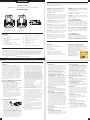
FEATURES
1. Power Switch
2. Power On Indicator
3. Mode Switch
For CP825AVRLCDG / CP685AVRLCDG
4. Fault Indicator
5. Mute Button
For CP800AVR / CP685AVRG
6. LCD module display
For CP825AVRLCDG / CP685AVRLCDG
7. Battery and Surge Protected Outlets
8. Full-Time Surge Protection Outlets
9. USB Port
10. Communication Protection Ports
For CP825AVRLCDG
11. Serial Port
12. Circuit Breaker and Reset
13. Ground Screw
14. Outlets Designed for AC Adapters
Thank you for purchasing a CyberPower product. This UPS is designed to provide unsurpassed
power protection, operation, and performance during the lifetime of the product. Please take
a few minutes to register your product at: www.CyberPowerSystems.com/registration. Regis-
tration certifies your product’s warranty, confirms your ownership in the event of a product loss
or theft, and entitles you to free technical support. Register your product now to receive the
benefits of CyberPower ownership.
CAUTION! To prevent the risk of fire or
electric shock, install in a temperature and
humidity controlled indoor area free of
conductive contaminants. (Please see
specifications for acceptable temperature
and humidity range).
CAUTION! To reduce the risk of electric shock,
do not remove the cover except to service the
battery. Turn o and unplug the unit before
servicing the batteries. There are no user ser-
viceable parts inside except for the battery.
CAUTION! Hazardous live parts inside can be
energized by the battery even when the AC
input power is disconnected.
CAUTION! The UPS must be connected to an
AC power outlet with fuse or circuit breaker
protection. Do not plug into an outlet that is
not grounded. If you need to de-energize this
equipment, turn o and unplug the unit.
CAUTION! To avoid electric shock, turn o the
unit and unplug it from the AC power source
before connecting equipment to the unit.
CAUTION! To reduce the risk of fire, connect
only to a circuit provided with 20 amperes
maximum branch circuit over current protec-
tion in accordance with the National Electric
Code, ANSI/NFPA 70.
CAUTION! Not for use in a computer room as
defined in the Standard for the Protection of
Electronic Computer / Data Processing Equip-
ment, ANSI/NFPA 75.
CAUTION! Do not dispose of batteries in a fire.
The batteries may explode.
CAUTION! Do not open or mutilate batteries.
Released electrolyte is harmful to the skin and
eyes. It may be toxic.
DO NOT USE FOR MEDICAL
OR LIFE SUPPORT EQUIPMENT!
CyberPower Systems does not sell products
for life support or medical applications. DO
NOT use in any circumstance that would aect
operation and safety of life support equip-
ment, any medical applications or patient care.
DO NOT USE WITH OR NEAR AQUARIUMS!
To reduce the risk of fire or electric shock, do
not use with or near an aquarium. Condensa-
tion from the aquarium can cause the unit to
short out.
DO NOT USE THE UPS
ON ANY TRANSPORTATION!
To reduce the risk of fire or electric shock, do
not use the unit on any transportation such
as airplanes or ships. The eect of shock or
vibration caused during transit and the damp
environment can cause the unit to short out.
PRODUCT REGISTRATION
IMPORTANT SAFETY WARNINGS (SAVE THESE INSTRUCTIONS)
This manual contains important safety instructions. Please read and follow all instructions carefully
during installation and operation of the unit. Read this manual thoroughly before attempting to
unpack, install, or operate your UPS.
INSTALLING YOUR UPS SYSTEM - continued
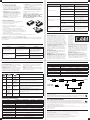
UNPACKING
Inspect the UPS upon receipt.
The box should contain the following:
(a) UPS unit
(b) User’s manual
(c) USB A+B type cable
PowerPanel® Personal software is
available on our website. Please visit
www.cyberpowersystems.com and go
to the Software Section for a free download.
AUTOMATIC VOLTAGE REGULATOR
The CP825AVRLCDG/CP685AVRLCDG/
CP800AVR/CP685AVRG stabilizes inconsistent
utility power to nominal levels that are safe for
equipment. Unstable utility power can be dam-
aging to important data and hardware.
With Automatic Voltage Regulation (AVR),
damaging voltage levels
are corrected to safe
levels. AVR automatically
increases low utility power
to a consistent and safe
110/120 volts.
BASIC OPERATION
INSTALLING YOUR UPS SYSTEM
1. Power Switch:
Used as the master on/o switch for equip-
ment connected to the battery power sup-
plied outlets. To turn the UPS ON, press the
power button for approximately 2 seconds
- you will hear a constant tone (1 second) -
and release after a short beep.
To turn the UPS OFF, press the power
button for approximately 2 seconds - you
will hear a constant tone (1 second) - and
release after two short beeps.
Alarm setting (For CP825AVRLCDG/
CP685AVRLCDG): The audible alarm can
be turned O or On by double clicking
the POWER button. The default setting is
for the Alarm On. To turn the Alarm O,
double click the button. You will hear two
short beeps when the Alarm is turned o.
To turn the Alarm back On, double click the
button. You will hear a single short beep
when the Alarm is turned on. *When the
Alarm is turned O, there will be no audible
notification when the UPS reaches a low
battery state.
2. Power On Indicator:
This LED is illuminated when the utility
power is normal and the UPS outlets are
providing power, free of surges and spikes.
3. Mode Switch
(For CP825AVRLCDG/CP685AVRLCDG):
Press the Mode Switch for approximately
3 seconds to enter setup mode to view
options: Utility High/low Voltage range,
sensitivity setup, LCD sleep ON/OFF, bat-
tery test, buzzer ON/OFF, and low battery
alarm. When an option is selected, wait for
8 seconds for the setting to be confirmed.
After the setting has been confirmed the
LCD screen will leave setup mode and go
back to status display. If there is no action
for 8 seconds during setup, the LCD will
also leave setup mode and go back to the
status display.
4. Fault Indicator:
This LED is illuminated if there is a problem
with the UPS.
5. Mute Button
(For CP800AVR/CP685AVRG):
Press the button for 2 seconds to enable
the audible alarm (beeps once) or disable
(beeps twice) the audible alarm.
6. LCD module display
(For CP825AVRLCDG/CP685AVRLCDG):
LCD display shows all the UPS information
using icons and messages. For more infor-
mation please review the “Definitions for
Illuminated LCD Indicators” section.
7. Battery and Surge Protected Outlets:
The unit has four battery powered and
surge protected outlets to ensure tempo-
rary uninterrupted operation of your equip-
ment during a power failure.
8. Full-Time Surge Protection Outlets:
The unit has four surge suppression outlets.
9. USB Port:
The USB port allows connection and com-
munication between the USB port on the
computer and the UPS unit.
10. Communication Protection Ports
(For CP825AVRLCDG):
Communication protection ports, bidirec-
tional, will protect a 10/100/1000 Ethernet
connection (RJ45).
11. Serial Port:
Serial Port allow for bi-directional commu-
nication among the UPS and the comput-
er.The UPS can control the computer’s
shutdown in case of an emergency, and at
the same time, the computer can monitor
the UPS and alter its various programmable
parameters.
12. Circuit Breaker and Reset:
Located on the side of the UPS, the
circuit breaker provides overload and
fault protection.
13. Ground Screw:
The ground screw is used for any
equipment that needs a chassis ground
connection.
14. Outlets Designed for AC Adapters:
The UPS unit has four widely-spaced out-
lets. AC power adapters can be plugged
into the UPS without overlapping or block-
ing adjacent outlets.
2
3 4
CP825AVRLCDG
CP685AVRLCDG
CP800AVR
CP685AVRG


 1
1
 2
2


CyberPower CP685AVRG User manual
CyberPower CP1500PFCRM2U User manual
CyberPower CP800AVR User manual
CyberPower BL1450U User manual
CyberPower CP1000AVRL User manual
CyberPower S175UC User manual
CyberPower MP92SS User manual
CyberPower P205UCPDQ User manual
Cyber Power CST150UC-FC User manual
Acer City650 User manual