Page is loading ...

APOGEE INSTRUMENTS, INC. | 721 WEST 1800 NORTH, LOGAN, UTAH 84321, USA
TEL: (435) 792-4700 | FAX: (435) 787-8268 | WEB: APOGEEINSTRUMENTS.COM
Copyright © 2022 Apogee Instruments, Inc.
OWNER’S MANUAL
DAILY LIGHT INTEGRAL AND
PHOTOPERIOD METER
Models: DLI-400, DLI-500, and DLI-600
Rev: 15-Sept-2022


CERTIFICATE OF COMPLIANCE
EU Declaration of Conformity
This declaration of conformity is issued under the sole responsibility of the manufacturer:
Apogee Instruments, Inc.
721 W 1800 N
Logan, Utah 84321
USA
for the following product(s):
Models: DLI-400, DLI-500, DLI-600
Type: Daily Light Integral and Photoperiod Meter
The object of the declaration described above is in conformity with the relevant Union harmonization legislation:
2014/30/EU Electromagnetic Compatibility (EMC) Directive
2011/65/EU Restriction of Hazardous Substances (RoHS 2) Directive
2015/863/EU Amending Annex II to Directive 2011/65/EU (RoHS 3)
Standards referenced during compliance assessment:
EN 61326-1:2013 Electrical equipment for measurement, control, and laboratory use – EMC requirements
EN 63000:2018 Technical documentation for the assessment of electrical and electronic products with
respect to the restriction of hazardous substances
Please be advised that based on the information available to us from our raw material suppliers, the products
manufactured by us do not contain, as intentional additives, any of the restricted materials including lead (see
note below), mercury, cadmium, hexavalent chromium, polybrominated biphenyls (PBB), polybrominated
diphenyls (PBDE), bis (2-ethylhexyl) phthalate (DEHP), butyl benzyl phthalate (BBP), dibutyl phthalate (DBP), and
diisobutyl phthalate (DIBP). However, please note that articles containing greater than 0.1 % lead concentration
are RoHS 3 compliant using exemption 6c.
Further note that Apogee Instruments does not specifically run any analysis on our raw materials or end products
for the presence of these substances, but we rely on the information provided to us by our material suppliers.
Signed for and on behalf of:
Apogee Instruments, September 2022
Bruce Bugbee
President
Apogee Instruments, Inc.

CERTIFICATE OF COMPLIANCE
UK Declaration of Conformity
This declaration of conformity is issued under the sole responsibility of the manufacturer:
Apogee Instruments, Inc.
721 W 1800 N
Logan, Utah 84321
USA
for the following product(s):
Models: DLI-400, DLI-500, DLI-600
Type: Daily Light Integral and Photoperiod Meter
The object of the declaration described above is in conformity with the relevant UK Statutory Instruments and
their amendments:
2016 No. 1091 The Electromagnetic Compatibility Regulations 2016
2012 No. 3032 The Restriction of the Use of Certain Hazardous Substances in Electrical and Electronic
Equipment Regulations 2012
Standards referenced during compliance assessment:
BS EN 61326-1:2013 Electrical equipment for measurement, control, and laboratory use – EMC requirements
BS EN 63000:2018 Technical documentation for the assessment of electrical and electronic products with
respect to the restriction of hazardous substances
Please be advised that based on the information available to us from our raw material suppliers, the products
manufactured by us do not contain, as intentional additives, any of the restricted materials including lead (see
note below), mercury, cadmium, hexavalent chromium, polybrominated biphenyls (PBB), polybrominated
diphenyls (PBDE), bis (2-ethylhexyl) phthalate (DEHP), butyl benzyl phthalate (BBP), dibutyl phthalate (DBP), and
diisobutyl phthalate (DIBP). However, please note that articles containing greater than 0.1 % lead concentration
are RoHS 3 compliant using exemption 6c.
Further note that Apogee Instruments does not specifically run any analysis on our raw materials or end products
for the presence of these substances, but we rely on the information provided to us by our material suppliers.
Signed for and on behalf of:
Apogee Instruments, September 2022
Bruce Bugbee
President
Apogee Instruments, Inc.

INTRODUCTION
The DLI meter calculates daily light integral (DLI) and photoperiod. DLI refers to the total amount of PAR or ePAR
incident on a plane in a 24-hour period, expressed in units of moles per square meter per day (mol m-2 d-1).
Photoperiod is the total amount of time in which PAR or ePAR is incident on a plane during a 24-hour period and is
expressed in units of hours (h). Both DLI and photoperiod influence plant growth and development, and they are
often measured in greenhouses and growth chambers to aid in light management and decision making.
Apogee Instruments DLI meters consist of a cast acrylic diffuser (filter), optical filter, photodiode, signal processing
circuitry, and an LCD display mounted in an ASA plastic housing. DLI meters are designed for single or continuous
measurements of PPFD or ePPFD; DLI; and photoperiod. The DLI meter uses a USB-C cable (included with the
meter) to download the stored data as a CSV file to a computer.
PAR vs ePAR
Radiation that drives photosynthesis is called photosynthetically active radiation (PAR) and is traditionally defined
as total radiation across a wavelength range of 400 to 700 nm. However, additional research has indicated that
photons outside of this range contribute to photosynthesis as well (Hogewoning et al., 2012; Murakami et al.,
2018; Zhen and van Iersel, 2017; Zhen et al., 2019). Research has shown that far-red photons, wavelength range
from 700 to 750 nm, work synergistically with photons in the traditional PAR range, but alone are inefficient at
driving photosynthesis (Zhen and Bugbee, 2020a; Zhen and Bugbee, 2020b). As a result, an extended PAR (ePAR)
definition has been proposed across a range of 400 to 750 nm (Zhen et al. 2021). Apogee DLI meters are designed
to measure either PAR (models DLI-400 and DLI-500) or ePAR (model DLI-600). The DLI-400 and DLI-500 both
measure PAR, however, the DLI-500 is accurate under all light sources, while the DLI-400 is a low-cost option that
is accurate under sunlight and some broadband light sources only. PAR and ePAR are often expressed as
photosynthetic photon flux density (PPFD) and extended photosynthetic photon flux density (ePPFD), respectively,
in units of micromoles per square meter per second (µmol m-2 s-1).
Hogewoning et al. 2012. Photosynthetic Quantum Yield Dynamics: From Photosystems to Leaves. The Plant Cell, 24: 1921–1935.
Murakami et al. 2018. A Mathematical Model of Photosynthetic Electron Transport in Response to the Light Spectrum Based on Excitation
Energy Distributed to Photosystems. Plant Cell Physiology. 59(8): 1643–1651.
Zhen et al. 2019. Far-red light enhances photochemical efficiency in a wavelength-dependent manner. Physiologia Plantarum. 167(1):21-33.
Zhen and Bugbee. 2020a. Far-red photons have equivalent efficiency to traditional photosynthetic photons: Implications for redefining
photosynthetically active radiation. Plant Cell and Environment. 2020; 1–14.
Zhen and Bugbee. 2020b. Substituting Far-Red for Traditionally Defined Photosynthetic Photons Results in Equal Canopy Quantum Yield for CO2
Fixation and Increased Photon Capture During Long-Term Studies: Implications for Re-Defining PAR. Frontiers in Plant Science. 11:1-14.
Zhen and van Iersel. 2017. Far-red light is needed for efficient photochemistry and photosynthesis. Journal of Plant Physiology. 209: 115–122.
Zhen S, van Iersel M and Bugbee B (2021) Why Far-Red Photons Should Be Included in the Definition of Photosynthetic Photons and the
Measurement of Horticultural Fixture Efficacy. Front. Plant Sci. 12:693445. doi: 10.3389/fpls.2021.693445

METER MODELS
This manual covers all three versions of the DLI meter. The table below shows available models and whether they
measure PAR or ePAR. See SPECIFICATIONS on page 6 for spectral differences between these models.
Model
Targeted Measurement
Meter Used For
DLI-400
PAR
Sunlight only
DLI-500
PAR
All lights
DLI-600
ePAR
All lights
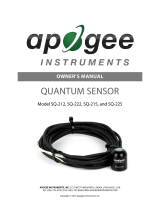
A DLI meter’s model number and serial
number are located on the bottom of the
meter. If the manufacturing date of a
specific meter is required, please contact
Apogee Instruments with the serial
number of the meter.

SPECIFICATIONS
DLI-400
DLI-500
DLI-600
Calibration Uncertainty
± 5 %
Measurement Repeatability
Less than 0.5 %
Display Range
0 to 4000 mol m-2 s-1
Long-term Drift per Year
Less than 2 % per year
Field of View
180°
Spectral Range (± 5 nm)
370 to 650 nm
390 to 690 nm
390 to 760 nm
Directional (Cosine) Response
± 5 % at 75° zenith angle
Azimuth Error
Less than 1 %
Temperature Response
-0.04 % per C
-0.11 ± 0.04 % per C
Measurement Frequency
3 minutes
Response Time
2.5 seconds
Data Log Capacity
99 days (DLI & Photoperiod), 10 days (30 min PPFD/ePPFD averages)
Non-linearity
Less than 1 % (up to
2500 mol m-2 s-1)
Less than 1 % (up to 4000 mol m-2 s-1)
Time Accuracy
± 53 seconds per month
Battery Type
2 AAA batteries
Battery Life
Approximately 6 months
ADC Resolution
24 bits
Mounting compatibility
Brass 1/4-20 threaded mount
Connectivity
CSV file via USB-C data transfer
Stored Data Resolution (PPFD)
0.1 µmol m-2 s-1 (when ≥ 1000, the screen will not display the decimal)
Stored Data Resolution (DLI)
0.1 mol m-2 day-1 (when ≥ 1000, the screen will not display the decimal)
Stored Data Resolution
(Photoperiod)
0.1 hours
Housing
ASA plastic
Ingress Protection
IP65
Operating Environment
-10 to 60 C; 0 to 100 %
relative humidity
-40 to 70 C; 0 to 100 % relative humidity
Dimensions
1.91 W x 2.31 H x 0.93 D (inches)
Mass
67 g
Warranty
4 years against defects in materials and workmanship
Calibration Traceability
Apogee DLI meters are calibrated through side-by-side comparison to the mean of transfer standard quantum
sensors placed under a reference LED (Ultraviolet: 1.5%; Blue: 36%; Green: 21%; Red: 41%; Far-Red: 0.5%). The
reference quantum sensors are recalibrated with a 200 W quartz halogen lamp traceable to the National Institute
of Standards and Technology (NIST).

Spectral Response and Spectral Error
Apogee DLI meters are calibrated to measure PPFD or ePPFD under sunlight and electric light. However, errors
occur in various light sources due to changes in spectral output. If the light source spectrum is known, then errors
can be estimated and used to adjust the measurements. The definitions, or weighting functions, of PPFD and
ePPFD are shown in the graph below, along with the spectral responses of the three DLI meter models. The closer
the spectral response matches the defined PPFD or ePPFD spectral weighting functions, the smaller the spectral
errors will be. The table below provides spectral error estimates for PPFD and ePPFD measurements from light
sources different than the calibration source. The method of Federer and Tanner (1966) was used to determine
spectral errors based on the PPFD and ePPFD spectral weighting functions, measured sensor spectral response,
and radiation source spectral outputs (measured with a spectroradiometer). This method calculates spectral error
and does not consider calibration, cosine, or temperature errors.
0.0
0.2
0.4
0.6
0.8
1.0
1.2
1.4
300 350 400 450 500 550 600 650 700 750 800 850 900
Relative Response to Photons
Wavelength [nm]
Mean spectral response of replicate DLI meters compared to PPFD and ePPFD weighting function. Spectral
response measurements were made at 10 nm increments across a wavelength range of 300 to 800 nm in a
monochromator with an attached electric light source. Measured spectral data from each meter were
normalized by the measured spectral output of the monochromator/electric light combination, which was
measured with a spectroradiometer.
PAR Definition
ePAR Definition
DLI-400
DLI-500
DLI-600

Radiation Source
DLI-400
DLI-500
DLI-600
PPFD Error [%]
PPFD Error [%]
ePPFD Error [%]
Clear Sky
0.0
0
1.8
Overcast
0.2
0.1
1.9
CWF T5
7.2
0.1
-1.2
Metal Halide
6.9
0.9
0.0
Ceramic Metal Halide
-8.8
0.3
-0.4
Mogul Base HPS
0.9
0.0
-0.4
Dual-ended HPS
-6.8
-0.1
-0.1
CW LED
9.4
0.9
-1.6
WW LED
-7.8
0.2
-1.0
Blue LED (442 nm)
12.1
-1.9
-3.3
Cyan LED (501 nm)
27.7
3.6
-1.4
Green LED (529 nm)
29.4
2.9
-1.4
Amber LED (598 nm)
2.0
-0.8
-1.0
Red LED (666 nm)
-55.8
2.7
-1.0
Federer, C. A., and C. B. Tanner, 1966. Sensors for measuring light available for photosynthesis. Ecology 47:654-
657.

Directional Response
Mean directional response of
replicate meters. Directional
response measurements were
made by direct side-by-side
comparison to the mean of
replicate reference quantum
sensors.
Directional, or cosine, response is defined as
the measurement error at a specific angle of
radiation incidence. Error for Apogee DLI
meter is approximately ± 5 % at solar zenith
75°.
-5
-4
-3
-2
-1
0
1
2
3
4
5
010 20 30 40 50 60 70 80 90
Difference [Percent]
Solar Zenith Angle [Degree]
DLI-400
DLI-500 and DLI-600

DEPLOYMENT AND INSTALLATION
Place the DLI meter wherever measurements are desired. To accurately measure PPFD incident on a horizontal
surface, the sensor must be level. The ¼-20 threaded mount can be used to secure the meter in place and ensure
consistent measurements. The mount also allows the use of most commercially available camera mounts, tripods,
and various stakes. The DLI meter comes with a yellow soil stake for easy, immediate deployment.
NOTE: The meter is officially IP65 rated against incoming dust and water. The meter is not rated for full immersion.
While some users have reported successful deployments underwater at shallow depths and short durations, doing
so may cause adverse effects or meter failure. Meter failure due to immersion is not covered by warranty.

MEASUREMENT AND OPERATION
Meter functionality covered in this section is the same for all models.
NOTE: Although the meter screen goes to sleep after three minutes of inactivity, the meter is always on in the
background taking measurements. To turn off the meter completely or to prevent the batteries from possibly
corroding inside the unit during long-term storage, we recommend removing the batteries (see the following
page).
Every 3 minutes, the DLI meter will automatically make 10 measurements over a 4-second period. These
measurements are averaged together and saved to internal memory as a single value, representative of the 3-
minute period. When 24 hours of data have been accumulated, a daily total (Daily Light Integral) is determined and
saved to internal memory.
Photoperiod is the accumulated number of hours (in a 24-hour period) in which the averaged measurement was
over 0.1 µmol m-2 s-1. Every 6 minutes of light will increase the displayed photoperiod total by 0.1 hours. Since
measurements are taken every 3 minutes, it is possible that the DLI meter can miss intermittent lighting events
shorter than 3 minutes.

Battery life is approximately 6 months. However, this can be reduced
by usage and ambient conditions. When batteries need to be changed,
the screen will display “bAtt Lo” upon waking up.
Note: For long-term storage, we recommend removing the
batteries.
IMPORTANT: Removing the bottom cover will result in the loss of all
current-day data.
FOR INITIAL SETUP – SKIP TO STEP 3
1. Using a small Phillips-head screwdriver, turn the two screws at the
bottom until they turn freely (this should take roughly 5 turns).
Note: The screws do not need to be fully removed.
2. Remove the bottom cover. With the screws loosened, the batteries should begin to push off the cover. If
needed, you can use the ¼-20 threaded mount with a matching bolt or screw to pull off the cover. If the cover
seems stuck, verify the screws completely unthreaded.
3. Install 2 AAA batteries into the bottom, making note of the proper polarity
marked next to each hole.
4. Replace the bottom cap and press firmly into place. The LCD screen should
turn on. If it does not, check the battery orientation and try again.
5.Using a small Phillips screwdriver, tighten the two screws on the bottom
cap by turning them until snug.
Note: Do NOT over-tighten the screws.
6. The meter is now ready to use and will begin making measurements as soon as the batteries are installed.
1. Turn on the display by pressing the button one time. The number displayed on the screen is a running average of
PPFD or ePPFD (depending on the model) from the last 2.5 seconds.
2. Press and hold the button for about 2 seconds to manually turn off the display.
Note: The display will automatically turn off after 3 minutes of inactivity. However, the meter is still on
taking measurements in the background.

1. Once the batteries are installed, the meter will automatically make a measurement every 3 minutes, whether
the screen is on or off.
2. Place the meter in the location you would like to measure and leave it there for the desired measurement
duration. See DEPLOYMENT AND INSTALLATION on page 10 for more information.
1. Turn on the display by pressing the button one time, which shows the current measurement.
2. Press the button one more time. Three numbers will appear on the display (shown in the photo). The first
number (bottom left of the display) indicates the day in which the data were collected (0 days ago is today, 1 day
ago was yesterday, and so on). The second and third numbers are the DLI and photoperiod in the top right and
bottom right corners, respectively.
3. Press the button repeatedly to cycle through all previously collected days and return to the live data view.
Notes:
• The meter will only display days in which data were collected.

• Press the button once to return to the live data view.
IMPORTANT: Transferring stored data requires removal of the bottom cover, which will result in the loss of all
current-day data.
1. Using a small Phillips-head screwdriver, turn the two screws
at the bottom until they turn freely (this should take roughly 5
turns).
Note: The screws do not need to be fully removed.
2. Remove the bottom cover. With the screws loosened, the
batteries should begin to push off the cover. If needed, you
can use the ¼-20 threaded mount with a matching bolt or
screw to pull off the cover. If the cover seems stuck, verify the
screws are completely unthreaded.
3. Connect a USB-C cable to the DLI meter and a computer.
Locate the meter (titled DLI METER) in file explorer as you
would a thumb drive. There will be three files in this drive:
ABOUT.TXT
This file contains calibration, firmware, and hardware information about your meter.
DLI.CSV
This four-column file contains the completed day number, days-ago label, DLI, and
photoperiod data up to 99 days.
MEAS.CSV
This two-column CSV contains a record number and 30-minute PPFD averages up to the
most recent 10 days.
Note: It can take up to 10 seconds for the DLI meter to connect to your computer.
4. Copy files to your computer.
5. Disconnect the USB-C cable.
6. Replace the bottom cover. Using a small Phillips screwdriver, replace the screws and tighten until snug.
Note: Do NOT over-tighten the screws.

1. Press and hold the button for about eight seconds until the reset
timer appears on the display. If you do not want to reset the meter,
release the button before the countdown is over to cancel the reset.
If you do want to reset the meter, continue holding the button until
the countdown reaches zero.
Note: Resetting the meter will clear ALL previous data and
begin new calculations beginning from that time. The first
‘day’ will last 24 hours or until the first hour of continuous
darkness (less than 0.1 mmol m-2 s-1) is detected, whichever
comes first. All subsequent days are 24 hours long.

MAINTENANCE AND RECALIBRATION
Moisture or debris on the diffuser is a common cause of low readings. The meter has a domed diffuser and housing
for improved self-cleaning from rainfall/irrigation, but materials can accumulate on the diffuser (e.g., dust during
periods of low rainfall, salt deposits from evaporation of sea spray or sprinkler irrigation water) and partially block
the optical path. Dust or organic deposits are best removed using water or window cleaner and a soft cloth or
cotton swab. Salt deposits should be dissolved with vinegar and removed with a soft cloth or cotton swab. Never
use an abrasive material or cleaner on the diffuser.
Although Apogee meters are very stable, nominal accuracy drift is normal for all research-grade instruments. To
ensure maximum accuracy, we generally recommend meters are sent in for recalibration every two years,
although you can often wait longer according to your particular tolerances.
To determine if your meter needs recalibration, the Clear Sky Calculator (www.clearskycalculator.com) website
and/or smartphone app can be used to indicate the PPFD and ePPFD on a horizontal surface at any time of day at
any location in the world. It is most accurate when used near solar noon in spring and summer months, where
accuracy over multiple clear and unpolluted days is estimated to be ± 4 % in all climates and locations around the
world. For best accuracy, the sky must be completely clear, as reflected radiation from clouds causes incoming
PPFD to increase above the value predicted by the Clear Sky Calculator. Measured values of PPFD can exceed
values predicted by the Clear Sky Calculator due to reflection from high, thin clouds and edges of clouds, which
enhances incoming PPFD. The influence of high clouds typically shows up as spikes above clear sky values, not a
constant offset greater than clear sky values.
To determine recalibration need, input site conditions into the calculator and compare PPFD measurements to
calculated values for a clear sky. If meter PPFD measurements over multiple days near solar noon are consistently
different than calculated values (by more than 6 %), the meter should be cleaned and re-leveled. If measurements
are still different after a second test, email calibration@apogeeinstruments.com to discuss test results and
possible return of sensor(s).

Homepage of the Clear Sky
Calculator. Two calculators
are available: one for
quantum meters (PPFD) and
one for pyranometers (total
shortwave radiation).
Clear Sky Calculator for
quantum sensors. Site data
are input in blue cells in the
middle of page and an
estimate of PPFD is
returned on right-hand side
of page.

TROUBLESHOOTING AND CUSTOMER SUPPORT
Independent Verification of Functionality
Apogee DLI meters display the current PPFD measurement. A quick and easy check of meter functionality can be
determined by directing the sensor head toward a light source and verifying the sensor provides a reasonable
measurement. Increase and decrease the distance from the sensor head to the light source to verify that the
measurement changes proportionally (decreasing signal with increasing distance and increasing signal with
decreasing distance). Blocking all radiation from the meter should force the meter to zero mol m-2 s-1.
Unit Conversion Charts
Apogee DLI meters are calibrated to measure PPFD or ePPFD in units of µmol m-2 s-1. Units other than photon flux
density (e.g., energy flux density, illuminance) may be required for certain applications. It is possible to convert the
PPFD or ePPFD value from a quantum sensor to other units, but it requires spectral output of the radiation source
of interest. Conversion factors for common radiation sources can be found on the Unit Conversions page in the
Support Center on the Apogee website (http://www.apogeeinstruments.com/unit-conversions/; scroll down to
Quantum Sensors section). A spreadsheet to convert PPFD or ePPFD to energy flux density or illuminance is also
provided on the Unit Conversions page in the Support Center on the Apogee website
(http://www.apogeeinstruments.com/content/PPFD-to-Illuminance-Calculator.xls).

RETURN AND WARRANTY POLICY
RETURN POLICY
Apogee Instruments will accept returns within 30 days of purchase as long as the product is in new condition (to be
determined by Apogee). Returns are subject to a 10 % restocking fee.
WARRANTY POLICY
What is Covered
All products manufactured by Apogee Instruments are warranted to be free from defects in materials and craftsmanship
for a period of four (4) years from the date of shipment from our factory. To be considered for warranty coverage, an
item must be evaluated by Apogee.
Products not manufactured by Apogee (spectroradiometers, chlorophyll content meters, EE08-SS probes) are covered
for a period of one (1) year.
What is Not Covered
The customer is responsible for all costs associated with the removal, reinstallation, and shipping of suspected warranty
items to our factory.
The warranty does not cover equipment that has been damaged due to the following conditions:
1. Improper installation, use, or abuse.
2. Operation of the instrument outside of its specified operating range, such as use underwater.
3. Natural occurrences such as lightning, fire, etc.
4. Unauthorized modification.
5. Improper or unauthorized repair.
Please note that nominal accuracy drift is normal over time. Routine recalibration of sensors/meters is considered part of
proper maintenance and is not covered under warranty.
Who is Covered
This warranty covers the original purchaser of the product or another party who may own it during the warranty period.
What Apogee Will Do
At no charge, Apogee will:
1. Either repair or replace (at our discretion) the item under warranty.
2. Ship the item back to the customer by the carrier of our choice.
Different or expedited shipping methods will be at the customer’s expense.
/