Page is loading ...

CRU-XP
Universal controller
CRU-XP_V1.9.1_PI_2019-12_EN Subject to technical changes Page 1 of 4
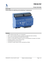
Front view
Features
Control process
Universal PID controller
Two-point controller
Three-point controller
Superheating controller
Multiple contact switch with 4 capacity steps
PWM operation with 0…10V analogue output
2 freely scalable analogue inputs 4…20mA
2 temperature sensor inputs
Constant setpoint shift via analogue input
4 digital multifunction inputs
Different baud rates possible on the C-BUS (20kBd, 50kBd, 125kBd)
Direct connection of a CAN-USB to the service socket
Connection to the Wurm system through a Wurm CAN communication bus (C-BUS) and
FRIGODATA XP

CRU-XP
Universal controller
Page 2 of 4 Subject to technical modifications CRU-XP_V1.9.1_PI_2019-12_EN
Writing conventions
Symbol Meaning
CAUTION Avoid the described hazard: otherwise minor or medium physical injury or
damage to property will result.
WARNING Avoid the described hazard: Otherwise there is danger from electric voltage
that can lead to death or serious bodily injury.
For your safety
For safe operation and to avoid personal injury and equipment damage through operator error, always
read these instructions, become familiar with the device, and follow all safety instructions on the
product and in this document, as well as the safety guidelines of Wurm GmbH & Co. KG Elektronische
Systeme. Keep these instructions ready to hand for quick reference and pass them on with the device
if the product is sold.
Wurm GmbH & Co. KG Elektronische Systeme accepts no liability in case of improper use or use for
other than the intended purpose.
Target group These instructions are intended for "service technicians".
Intended use The universal controller CRU-XP can be used for constant, two-point and
three-point control of consumers with both stepped and stepless control.
WARNING
Danger to life from electric shock and/or fire!
Switch off the power to the entire plant when installing, wiring or removing. Otherwise a
mains voltage and/or external voltage may still be present even if the control voltage is
switched off. Always remove both power plugs (L and N).
Only qualified electricians are permitted to wire the device.
Use only the correct tools for all work.
Check all wiring after connection.
Take note of the maximum loads on all connections.
Never expose the device to moisture, for example due to condensation or cleaning
agents.
Take the device out of operation if it is faulty or damaged and is therefore compromising
safe operation.
Do not open the device.
Do not repair the device yourself. If the device requires repairs, send it in with an exact
description of the fault.
CAUTION
Electromagnetic interference can cause faults!
Use only shielded data lines and place them far away from power lines.
Wurm Infocenter
paperless info
Software revisions and validity of documentation
Software version
V1.9.1 2019-12 Documentation status
Any software versions not listed are special solutions for individual projects and are not described in detail in this
document. This document automatically ceases to be valid if a new technical description is issued.
Manufacturer: Wurm GmbH & Co. KG Elektronische Systeme, Morsbachtalstraße 30, D-42857 Remscheid
For further information, see our website at www.wurm.de

CRU-XP
Universal controller
CRU-XP_V1.9.1_PI_2019-12_EN Subject to technical changes Page 3 of 4
Circuit diagram
C-BUS interface Output relays
Digital inputs
Installing and connecting
WARNING
Danger to life from electric shock and/or fire!
Switch power off to the entire plant when installing and wiring. Otherwise a mains
voltage and/or external voltage may still be present even if the control voltage is
switched off. Always remove both power plugs (L and N).
This device is designed for top-hat rail
installation. The housing is a standard size and is
also suitable for installation in fuse boxes.
The devices can be positioned next to one
another without gaps.
53
106
90
58

CRU-XP
Universal controller
Page 4 of 4 Subject to technical modifications CRU-XP_V1.9.1_PI_2019-12_EN
Place the device with the upper guide edge on
the top-hat rail.
Then press the device gently downward until it
engages with the fastening safety catch on the
top-hat rail.
When wiring the data lines, please refer to the description of the "FRIGOENTRY bus system".
We recommend the use of shielded cables for sensor extension.
Cable length Cross section
Up to 100m 0.75mm²
Up to 400m 1.5mm²
Technical data
Power supply 230V~, +10% / -15%, approx. 5VA
Temperature sensor 2 x TRK277 or DGF
Current input 2 x current input, 4…20mA (I1 and І2)
Digital inputs Inputs for voltage-free contacts:
4 x multifunction input
Output relay 4 x normally open contact, 230V~, 4(2)A, rated voltage 250V~
Analogue output 1 x 0…10V=, non-isolated, max. load 1mA, alternatively for actuating
an electronic relay ATV230
Central unit Single-chip microcomputer, data memory
Monitoring system Monitoring of connected sensors, self-monitoring of data memory
and microcomputer
Communication 3-wire CAN bus interface with integrated power supply, galvanically
isolated, service socket
Dimensions (WxHxD) 106 x 90 x 58mm (DIN 43880)
Fastening Top-hat rail TH 35-15 or TH 35-7.5 (DIN EN 60715)
Ambient temperature Operation: 0...+55°C, storage: -25...+70°C
Weight About 450g
CE conformity 2014/30/EU (EMC Directive)
2014/35/EU (Low Voltage Directive)
EAC conformity TR CU 004/2011
TR CU 020/2011
RoHS II
Valid from Version 1.9.1
/