Page is loading ...

Instruction
Manual
Press Force Sensor
Typ
9313, 9323,
9333, 9343,
9363
9260AA_002-479e-11.12
Portable
Multicomponent
Force Plate for Gait-
and Balance Analysis
in Biomechanics
Type 9260AA...
ä

Instruction
Manual
Portable Multicom-
ponent Force Plate
for Gait and Balance
Analysis
in Biomechanics
Type 9260AA...
9260A_002-479e-11.12
Portable
Multicomponent
Force Plate for Gait-
and Balance Analysis
in Biomechanics
Type 9260AA…
ä


Foreword
9260A_002-479e-11.12 Page 1
Foreword
We thank you for choosing a Kistler quality product distin-
guished by technical innovation, precision and long life.
Information in this document is subject to change without
notice. Kistler reserves the right to change or improve its
products and make changes in the content without obliga-
tion to notify any person or organization of such changes
or improvements.
©2008 … 2012 Kistler Group. All rights reserved. Except as
expressly provided herein, no part of this manual may be
reproduced for any purpose without the express prior writ-
ten consent of Kistler Group.
Kistler Group
Eulachstrasse 22
8408 Winterthur
Switzerland
Tel. +41 52 224 11 11
Fax +41 52 224 14 14
info@kistler.com
www.kistler.com

181BPortable Multicomponent Force Plate for Gait and Balance Analysis
in Biomechanics 182BType 9260AA...
Page 2 9260A_002-479e-11.12
Content
1. Introduction ................................................................................................................................... 4
2. Important Information .................................................................................................................... 5
2.1 For your Safety ..................................................................................................................... 5
2.2 ä-Conformity ..................................................................................................................... 6
2.3 How to Treat the Instrument ................................................................................................ 6
2.4 Hints for Using the Operating Instructions ........................................................................... 6
2.5 What Happens After Modifications? .................................................................................... 7
2.6 Disposal Instructions for Electrical and Electronic Equipment ................................................ 7
3. General Description of the Instrument ........................................................................................... 8
3.1 What does a Multicomponent Force Plate Do? .................................................................... 8
3.2 Available in Two Different Sizes ........................................................................................... 9
3.3 Application Examples ........................................................................................................... 9
3.4 Functional Principle .............................................................................................................. 9
3.5 Design of the Force Plate ................................................................................................... 11
4. Assembly, Installation and Putting Into Operation ...................................................................... 12
4.1 Important Remarks ............................................................................................................. 12
4.2 Choice of Location ............................................................................................................. 13
4.3 Placing the Force Plate ....................................................................................................... 14
4.3.1 Floor Recessing 16
4.3.2 Arranging Several Force Plates Side by Side ........................................................................ 17
4.4 Versatile Mounting ............................................................................................................. 17
4.4.1 Walkway Type 9428A for Mounting on Floor .................................................................... 18
4.4.2 Permanent, Flush Mounting in Floor .................................................................................. 19
4.5 Basic Circuitry and Cabling of the Measuring System ......................................................... 20
4.6 Connections with Built-In Amplifier (Type 9260AA…) ....................................................... 21
4.6.1 Connector of Force Plate Type 9260AA… with Built-In Amplifier ...................................... 22
4.6.2 Cable Type 1769A... .......................................................................................................... 23
4.6.3 Digital Contro……l ............................................................................................................ 24
5. Operation ..................................................................................................................................... 25
5.1 Range Selection .................................................................................................................. 25
5.2 Operate/Reset.................................................................................................................... 25
5.2.1 Balance (Balance Analysis, Posturography) ......................................................................... 26
5.3 Usable Frequency Range .................................................................................................... 26
5.4 Temperature Influences ...................................................................................................... 27
5.5 Polarity of the Measuring Signal ......................................................................................... 27
5.5.1 x- and y-Directions ............................................................................................................. 27
5.5.2 z-Direction………. ............................................................................................................. 27

Content
9260A_002-479e-11.12 Page 3
6. Maintenance ................................................................................................................................. 28
6.1 Recalibration of the Instrument ........................................................................................... 28
6.2 Weekly Function Check ...................................................................................................... 29
6.2.1 System Check……. ............................................................................................................. 29
6.2.2 Drift Check………. .............................................................................................................. 29
6.2.3 Check Gap Around Force Plate ........................................................................................... 29
6.2.4 Setup Parameters.. .............................................................................................................. 29
6.3 Maintenance ....................................................................................................................... 30
6.4 Cleaning and Sterilization .................................................................................................... 30
7. Troubleshooting ........................................................................................................................... 31
7.1 Defective Force Plate .......................................................................................................... 31
8. Technical Data .............................................................................................................................. 32
8.1 Dimensions and Connections .............................................................................................. 32
8.2 Technical Data for Type 9260AA… ..................................................................................... 33
8.2.1 General………….. ............................................................................................................... 33
8.2.2 Built-In 8 Channel Charge Amplifier .................................................................................... 35
8.3 Frequency Response ........................................................................................................... 36
9. Glossary ........................................................................................................................................ 37
9.1 Coordinate System .............................................................................................................. 37
9.2 Kistler Coordinate System ................................................................................................... 37
9.2.1 ISB Coordinate System ........................................................................................................ 38
9.3 Parameters Calculation........................................................................................................ 38
10. Warranty ....................................................................................................................................... 39
11. Declaration of Conformity ............................................................................................................ 40
Total Pages 41

Introduction
9260A_002-479e-11.12 Page 4
1. Introduction
Please take the time to thoroughly read this instruction
manual. It will help you with the installation, maintenance,
and use of this product.
To the extent permitted by law Kistler does not accept any
liability if this instruction manual is not followed or prod-
ucts other than those listed under Accessories are used.
Kistler offers a wide range of products for use in measuring
technology:
Piezoelectric sensors for measuring force, torque, strain,
pressure, acceleration, shock, vibration and acoustic-
emission
Strain gage sensor systems for measuring force and
moment
Piezoresistive pressure sensors and transmitters
Signal conditioners, indicators and calibrators
Electronic control and monitoring systems as well as
software for specific measurement applications
Data transmission modules (telemetry)
Kistler also develops and produces measuring solutions for
the application fields engines, vehicles, manufacturing,
plastics and biomechanics sectors.
Our product and application brochures will provide you
with an overview of our product range. Detailed data
sheets are available for almost all products.
If you need additional help beyond what can be found ei-
ther on-line or in this manual, please contact Kistler's ex-
tensive support organization.

Important Information
9260A_002-479e-11.12 Page 5
2. Important Information
Please keep to the following rules without fail. This will en-
sure your personal safety when working, and assure long,
trouble-free performance by the instrument.
2.1 For your Safety
This instrument has been tested thoroughly and it left
the works in a perfectly safe condition. To maintain this
condition and assure safe operation, the user must ob-
serve the directives and warnings contained in these in-
structions
The force plate must be installed, operated and main-
tained only by persons who are familiar with it and ad-
equately qualified for their particular tasks
When it must be assumed that safe operation is no
longer possible, the instrument must be taken out of
operation and secured against unintentional use
It must be assumed that safe operation is no longer possi-
ble if:
the instrument is visibly damaged
it no longer functions
it has been in lengthy storage under adverse conditions
it has received rough treatment during transport
Please mount the force plate on its foundation following
the instructions in chapter 4. Assembly, installation and
putting into operation.
According to safety requirements the following has to be
observed:
The force plate has to be connected to earth using the
Potential Equalization Conductor provided in the scope
of delivery to meet the ä-standards regarding Earth
Leakage Current.
The data acquisition computer and persons who are in
direct contact with it have to remain in a distance of
1,5 m from the patient at all times for the same reason.

181BPortable Multicomponent Force Plate for Gait and Balance Analysis
in Biomechanics 182BType 9260AA...
Page 6 9260A_002-479e-11.12
2.2
ä
-Conformity
The Force Plate Type 9260AA… is conforming to ä direc-
tives according to the Declaration of Conformity enclosed
with these operating instructions.
2.3 How to Treat the Instrument
The force plate may be used only under the specified
environmental and operating conditions
Protect the signal output against dirt and do not touch
it with your fingers. When the connection is not being
used, cover it with the cap provided
When the force plate is not in use, protect it by keeping
it in the packing case supplied
When performing long-time measurements, make sure
that the temperature of the force plate remains as con-
stant as possible
2.4 Hints for Using the Operating Instructions
We recommend reading the entire Operating Instructions
as a matter of principle. If you're in a hurry, however, and
you've already gathered experience with Kistler force
plates, you can confine your reading to the information
that you really need.
We have endeavored to arrange these instructions so that
you can find the information you need without difficulty.
Please keep these Operating Instructions in a safe place
where they can be consulted any time.
If the instructions get lost, just turn to your Kistler distribu-
tor and they will be replaced without delay.
All information and directives in these instructions may be
modified at any time without prior notification.

Important Information
9260A_002-479e-11.12 Page 7
2.5 What Happens After Modifications?
Modifications to instruments result in alterations of the op-
erating instructions as a rule. In such cases, enquire at your
Kistler distributor about the possibilities of updating your
documentation.
2.6 Disposal Instructions for Electrical and Electronic Equipment
Do not discard old electronic instruments in municipal
trash. For disposal at end of life, please return this prod-
uct to an authorized local electronic waste disposal ser-
vice or contact the nearest Kistler Instrument sales office
for return instructions.

181BPortable Multicomponent Force Plate for Gait and Balance Analysis
in Biomechanics 182BType 9260AA...
Page 8 9260A_002-479e-11.12
3. General Description of the Instrument
3.1 What does a Multicomponent Force Plate Do?
The multicomponent force plate provides dynamic and
quasistatic measurement of the 3 orthogonal components
of a force (Fx, Fy, Fz) acting from any direction on the top
plate.
With the aid of optional evaluation devices (e.g. software
system BioWare®) the following quantities can also be
measured:
The moments Mx, My and Mz
The coordinates ax and ay of the point of application of
force on the force plate surface COP = Center of Pres-
sure
The torque Tz (free moment) about an axis normal to
the force plate surface
Center of mass displacement and acceleration, physical
power and work, coefficient of friction
The multicomponent force plate Type 9260AA… has the
following outstanding features:
Excellent center of pressure (COP) accuracy
Available in two different sizes
Easy mounting
Flexible, mobile application
Versatile installation
Threshold Fz <250 mN
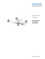
Fig. 1: Portable multicomponent force plate Type
9260AA…

General Description of the Instrument
9260A_002-479e-11.12 Page 9
3.2 Available in Two Different Sizes
The force plate Type 9260AA... is available in two different
sizes:
Type 9260AA6 with 600x500 mm
Type 9260AA3 with 300x500 mm
3.3 Application Examples
The force plate is designed specifically for use in gait and
balance analysis. The Type 9260AA... is fitted with an inte-
grated charge amplifier compatible with all of the current
motion analysis systems. The force plate is ideal for meas-
uring slow and medium-fast activities, where center of
pressure accuracy is particularly important, or portability
necessary.
Gait analysis, for example recording of the forces exert-
ed by our feet while standing, walking or running
Balance analysis, orthopedic investigations and posturo-
graphy
Determining rehabilitation progress, for example with
prostheses, after fractures, etc.
Coefficients of friction can be determined statically and
dynamically with the BioWare software package
For dynamic applications (e.g. in sports) it is advisable
to use a force plate with very high natural frequency,
such as Type 9281E… or Type 9287C… .
3.4 Functional Principle
The force to be measured is introduced via a top plate and
distributed between four 3-component force sensors ar-
ranged between mounting base and top plate.
Each of the sensors has three pairs of quartz plates, one
sensitive to pressure in the z-direction and the other two to
shear in the x- and y-directions respectively. The measure-
ment is virtually without displacement.

181BPortable Multicomponent Force Plate for Gait and Balance Analysis
in Biomechanics 182BType 9260AA...
Page 10 9260A_002-479e-11.12
In these four force sensors the force introduced is resolved
into three components.
Fig. 2: 3-component force sensor
The electrical charges yielded by the force plate are strictly
proportional to the measured quantities. They are convert-
ed by charge amplifiers into analog voltages and can then
be processed in any way.
Negative charges give positive voltages at the output of
the charge amplifier, and vice versa.
Out of the 12 output signals of the 4 sensors, 2 each of
the shear forces which have the same line of action can be
paralleled (e.g. Fx1 and Fx2 to obtain Fx1+2, etc.). Therefore,
only 8 signals are needed for further processing.
Fig. 3: Force plate output signals

General Description of the Instrument
9260A_002-479e-11.12 Page 11
3.5 Design of the Force Plate
The force plate has an aluminum sandwich cover plate un-
der which the four 3-component force sensors are mount-
ed under a high preload.
This preload is a prerequisite for transmitting shear forces
by friction.
Fig. 4: Dimensions and assembly of the multicomponent
force plate Type 9260AA…
The four preloading bolts constitute at the same time the
legs on which the force plate stands. The bases are at-
tached movable at the convex lower ends of the legs.
This design allows extremely accurate measurements de-
spite the thin top plate.
To compensate for unevenness, washers may be fitted be-
tween the preloading bolts and the bases. The non-slip
covering underneath the bases prevents the force plate
from slipping away.
If the force plate is recessed into the floor or a walkway,
the projecting bases prevent contact between the top plate
and the frame, which might otherwise cause measuring er-
rors.

181BPortable Multicomponent Force Plate for Gait and Balance Analysis
in Biomechanics 182BType 9260AA...
Page 12 9260A_002-479e-11.12
4. Assembly, Installation and Putting Into Operation
4.1 Important Remarks
The multicomponent force plate Type 9260AA... is a preci-
sion instrument, however its inherent accuracy can only be
exploited and retained if it is treated carefully. The follow-
ing points should be observed:
Never drop the force plate or expose it to heavy im-
pacts! The maximum force of a shock of this kind could
exceed the measuring range of the instrument and
cause damage
For safety reasons the force plate must be connected to
protective ground with a separate ground wire, using
the 6,3x0,8 connector provided for this purpose on the
underside of the plate
A modular walkway Type 9418A… opens up very cost-
effective, versatile mounting options for one or more
force plates. It can be mounted without construction
work
Mounting frames Type 9428A... are available for per-
manent or flush mounting in the floor. It is also possible
to install multiple frames that allow mounting of several
force plates and dummies in different arrangements
The force plate may only be mounted by persons suita-
bly qualified for this work
Please refer to the instruction Manual 002-034 "Force
Plate Installation and Maintenance" for detailed proce-
dures and information.
For nonobservance of the mounting instructions Kistler will
decline all responsibility.

Assembly, Installation and Putting Into Operation
9260A_002-479e-11.12 Page 13
4.2 Choice of Location
The portable multicomponent force plate Type 9260AA…
needs no foundation and can therefore be set up any-
where. Nevertheless the location must satisfy certain re-
quirements listed below, if exact and reproducible meas-
urements are to be obtained.
Suitable surfaces for placing the force plate are concrete,
cement and linoleum floors with hard subfloor.
The floor must be clean and slip-proof to ensure a firm
placement of the force plate
The floor must be level. Only minimal unevenness up to
2,0 mm can be compensated for with the washer set
between bases and preloading bolts
The floor must be hard. If it is too soft (like carpeting,
wood, earth) the behavior of the force plate will deteri-
orate for dynamic measurements, or it will sink in under
load
The floor must transmit little vibration. Even small vibra-
tions may disturb the measurements considerably

181BPortable Multicomponent Force Plate for Gait and Balance Analysis
in Biomechanics 182BType 9260AA...
Page 14 9260A_002-479e-11.12
4.3 Placing the Force Plate
Thoroughly clean the floor on which the force plate is
to stand, and allow it to dry
Carefully place the force plate on the floor and bring it
into position
Check whether the force plate rocks by pressing strong-
ly and alternately on diagonally opposite corners of it
If rocking is detected, it must be eliminated with the
washers supplied, even if the rocking is only slight. The
bases of the force plate can be removed by hand for
this
The feet of the plate can be removed by hand to enable
insertion of the washers
The feet of the force plate are provided with a very ef-
fective textured finish to prevent people slipping acci-
dentally
If required, the feet can also be screwed to the floor
with M6 screws. A gage must be used to ensure the
feet are positioned very accurately
Fig. 5: Washer for compensating floor unevenness
Always shim the force plate at one corner only, never
using more than 2 mm of washers altogether. Often a
position free from rocking can be found very easily by
shifting the force plate to and fro a little and repeatedly
checking it for rocking.

Assembly, Installation and Putting Into Operation
9260A_002-479e-11.12 Page 15
Fig. 6: The feet of the force plate can be turned so they
project either 1,5 mm or 3 mm as required
To rule out the possibility of force shunts causing
meas
uring errors, the cover plate of the force plate
must be positioned with a gap of at least 3 mm from
the surroundings or the next force plate. The feet of
the plate therefore project beyond the cover plate.

181BPortable Multicomponent Force Plate for Gait and Balance Analysis
in Biomechanics 182BType 9260AA...
Page 16 9260A_002-479e-11.12
4.3.1 Floor Recessing
If the force plate is to be used for gait analysis it must be
recessed into the floor and provided with the same floor
covering as its surroundings. This will prevent the test per-
son concentrating too much on the plate so that his gait is
altered.
When the force plate is recessed, into a walkway for ex-
ample, make sure that neither the top plate nor the floor
covering fixed on it touch the surroundings. This prevents
force shunts, which can lead to measuring errors. To avoid
this the feet are turned so their round surface projects
3 mm beyond the cover plate.
Fig. 7: Recessed force plate. The 3 mm projecting bases
prevent the top plate touching the surroundings

Assembly, Installation and Putting Into Operation
9260A_002-479e-11.12 Page 17
4.3.2 Arranging Several Force Plates Side by Side
In order to arrange several force plates Type 9260AA...
right next to each other the feet have to be turned so they
still project only 1,5 mm beyond each plate (smooth sur-
face on the foot). This achieves a total gap of 3 mm.
Fig. 8: 2 force plates Type 9260AA... in parallel
4.4 Versatile Mounting
The walkway solution opens up very cost-effective yet
versatile options for mounting one or more force plates
Different mounting frames are available for permanent
or flush installation in the floor
It is also possible to install multiple frames that allow
mounting of several force plates and dummies in differ-
ent arrangements
/