Sonel MPI-535 User manual
- Category
- Measuring, testing & control
- Type
- User manual


USER MANUAL
METER FOR ELECTRICAL
INSTALLATION PARAMETERS
MPI-535
SONEL S.A.
Wokulskiego 11
58-100 Świdnica
Poland
Version 1.10 05.10.2022

MPI-535 – USER MANUAL
2
MPI-535 meter is a modern, easy in use and safe measuring device. Please acquaint your-self with this
manual in order to avoid measuring errors and prevent possible problems in operation of the meter.

MPI-535 – USER MANUAL
3
CONTENTS
1 Safety ................................................................................................................ 6
2 Main menu ........................................................................................................ 7
2.1 Meter settings........................................................................................................... 8
2.1.1 Setting date and time ....................................................................................................... 9
2.1.2 Automatic shutdown ...................................................................................................... 10
2.1.3 Display parameters ........................................................................................................ 11
2.2 Settings of measurements ..................................................................................... 12
2.2.1 Sub-menu Measurement Settings .................................................................................. 12
2.2.2 Sub-menu Edit fuses ..................................................................................................... 14
a. Adding fuse characteristics .......................................................................................... 14
b. Adding fuses ................................................................................................................ 19
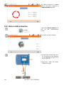
2.3 Communication ...................................................................................................... 21
2.3.1 USB communication ...................................................................................................... 21
2.3.2 Connection to a Wi-Fi network ....................................................................................... 21
2.3.3 E-mail settings ............................................................................................................... 21
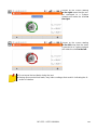
2.4 Update ................................................................................................................... 22
2.4.1 Update via USB ............................................................................................................. 22
2.4.2 Update via Wi-Fi ............................................................................................................ 22
2.5 Regional settings ................................................................................................... 23
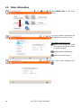
2.6 Meter information ................................................................................................... 24
3 Measurements ................................................................................................ 25
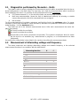
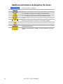
3.1 Diagnostics performed by the meter – limits .......................................................... 26
3.2 Measurement of alternating voltage and frequency ............................................... 26
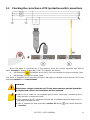
3.3 Checking the correctness of PE (protective earth) connections ............................ 27
3.4 Fault loop parameters ............................................................................................ 28
3.4.1 Settings of measurements ............................................................................................. 28
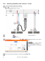
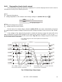
3.4.2 Fault loop parameters in the L-N and L-L circuits ........................................................... 30
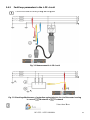
3.4.3 Fault loop parameters in the L-PE circuit ....................................................................... 33
3.4.4 Fault loop impedance in L-PE circuit protected with a residual current device (RCD) .... 36
3.4.5 Prospective short-circuit current .................................................................................... 39
3.4.6 Measurement of fault loop impedance in IT networks .................................................... 40
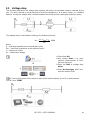
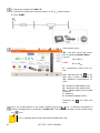
3.5 Voltage drop ........................................................................................................... 41
3.6 Resistance-to-earth ................................................................................................ 43
3.6.1 Settings of measurements ............................................................................................. 43
3.6.2 Earth resistance measurement with 3-pole method (RE3P) ............................................ 44
3.6.3 Earth resistance measurement with 4-wire method (RE4P) ............................................ 48
3.6.4 Earth resistance measurement with 3-pole method with additional clamp (RE3P+C) ..... 52
3.6.5 Earth resistance measurement with two-clamp method (2C) ......................................... 56
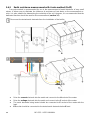
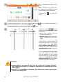
3.7 Soil resistivity ......................................................................................................... 59
3.7.1 Settings of measurements ............................................................................................. 59
3.7.2 Main elements of the screen .......................................................................................... 60
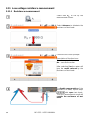
3.7.3 Soil resistivity measurements (ρ) ................................................................................... 61
3.8 RCD parameters .................................................................................................... 65
3.8.1 Settings of measurements ............................................................................................. 65
3.8.2 RCD tripping current ...................................................................................................... 68
3.8.3 RCD tripping time .......................................................................................................... 71
3.8.4 Measurements in IT networks ........................................................................................ 74
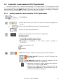
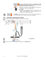
3.9 Automatic measurements of RCD parameters....................................................... 75
3.9.1 Setting automatic measurements of RCD parameters ................................................... 75
3.9.2 Automatic measurement of RCDs .................................................................................. 76

MPI-535 – USER MANUAL
4
3.10 Insulation resistance .............................................................................................. 81
3.10.1 Settings of measurements ............................................................................................. 81
3.10.2 Measurement using probes............................................................................................ 85
3.10.3 Measurements using UNI-Schuko adapter (WS-03 and WS-04) .................................... 87
3.10.4 Measurements using AutoISO-1000c ............................................................................ 90
3.11 Low-voltage resistance measurement ................................................................... 94
3.11.1 Resistance measurement .............................................................................................. 94
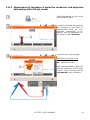
3.11.2 Measurement of resistance of protective conductors and equipotential bonding
with ±200 mA current ..................................................................................................... 97
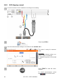
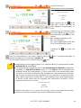
3.12 Phase sequence .................................................................................................. 101
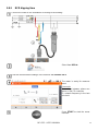
3.13 Motor rotation direction ........................................................................................ 102
3.14 Illuminance ........................................................................................................... 104
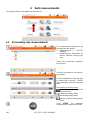
4 Auto measurements .................................................................................... 106
4.1 Proceeding auto measurements .......................................................................... 106
4.2 Creating measurement procedures ...................................................................... 108
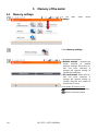
5 Memory of the meter .................................................................................... 110
5.1 Memory settings ................................................................................................... 110
5.2 Structure of the Memory ....................................................................................... 111
5.2.1 Fundamentals of navigating the Memory menu ............................................................ 112
5.2.2 Adding a new measurements tree................................................................................ 114
5.3 Entering the measurement result ......................................................................... 119
5.4 Viewing saved measurements ............................................................................. 120
5.5 Sharing recorded measurements ......................................................................... 122
5.6 Searching the meter memory ............................................................................... 123
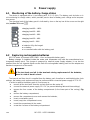
6 Power supply ................................................................................................ 124
6.1 Monitoring of the battery charge status ................................................................ 124
6.2 Replacing rechargeable batteries ........................................................................ 124
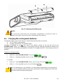
6.3 Charging the rechargeable batteries .................................................................... 125
6.4 General rules for using Li-Ion rechargeable batteries .......................................... 126
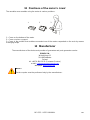
7 Cleaning and maintenance ......................................................................... 127
8 Storage .......................................................................................................... 127
9 Dismantling and utilisation ......................................................................... 127
10 Technical data .............................................................................................. 128
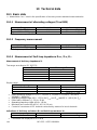
10.1 Basic data ............................................................................................................ 128
10.1.1 Measurement of alternating voltages (True RMS) ........................................................ 128
10.1.2 Frequency measurement ............................................................................................. 128
10.1.3 Measurement of fault loop impedance ZL-PE, ZL-N, ZL-L ................................................. 128
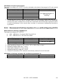
10.1.4 Measurement of fault loop impedance ZL-PE[RCD] (without triggering of RCD) ........................... 129
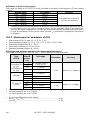
10.1.5 Measurement of parameters of RCD ........................................................................... 130
10.1.6 Measurement of resistance-to-earth RE ....................................................................... 133
10.1.7 Low-voltage measurement of continuity of circuit and resistance ................................. 134
10.1.8 Measurement of insulation resistance .......................................................................... 135
10.1.9 Light measurements .................................................................................................... 136
10.1.10 Phase sequence .......................................................................................................... 137
10.1.11 Motor rotation .............................................................................................................. 137
10.2 Other technical data ............................................................................................. 137
10.3 Additional data ..................................................................................................... 138

MPI-535 – USER MANUAL
5
10.3.1 Additional uncertainties according to IEC 61557-2 (RISO) ............................................. 138
10.3.2 Additional uncertainties according to IEC 61557-3 (Z) ................................................. 138
10.3.3 Additional uncertainties according to IEC 61557-4 (R ±200 mA) .................................. 138
10.3.4 Additional uncertainties of earth resistance measurement (RE) .................................... 138
10.3.5 Additional uncertainties according to IEC 61557-6 (RCD) ............................................ 139
10.4 List of reference standards .................................................................................. 140
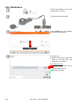
11 Accessories .................................................................................................. 140
12 Positions of the meter’s cover .................................................................... 141
13 Manufacturer ................................................................................................ 141

MPI-535 – USER MANUAL
6
1 Safety
MPI-535 meter is designed for performing check tests of protection against electric shock in AC
mains systems and recording the parameters of electric mains. The meter is used for making meas-
urements and providing results to determine safety of electrical installations. Therefore, in order to
provide conditions for correct operation and accuracy of obtained results, the following recommenda-
tions must be observed:
Before you proceed to operate the meter, acquaint yourself thoroughly with the present manual
and observe the safety regulations and specifications provided by the producer.
Any application that differs from those specified in the present manual may result in a damage to
the device and constitute a source of danger for the user.
MPI-535 meters must be operated only by appropriately qualified personnel with relevant certifi-
cates authorising the personnel to perform works on electric systems. Operating the meter by un-
authorised personnel may result in damage to the device and constitute a source of danger for
the user.
Using this manual does not exclude the need to comply with occupational health and safety regu-
lations and with other relevant fire regulations required during the performance of a particular type
of work. Before starting the work with the device in special environments, e.g. potentially fire-
risk/explosive environment, it is necessary to consult it with the person responsible for health and
safety.
It is unacceptable to operate:
a damaged meter which is completely or partially out of order,
a meter with damaged insulation,
a meter stored for an excessive period of time in disadvantageous conditions (e.g. excessive
humidity). If the meter has been transferred from a cool to a warm environment with a high
level of relative humidity, do not start measurements until the meter is warmed up to the am-
bient temperature (approximately 30 minutes).
If the battery is discharged to a level preventing further measurements, the meter displays an ap-
propriate message and then turns off.
Battery spill and damage to the meter may occur if discharged batteries are left in the meter.
Before measurements may commence, make sure the leads are connected to the appropriate
measurement sockets.
Do not operate a meter with an open or incorrectly closed battery (accumulator) compartment or
power it from other sources than those specified in the present manual.
RISO meter inputs are electronically protected against overloads (caused by e.g. connecting the
meter to a live circuit) up to 463 V RMS for 60 seconds.
Repairs may be performed only by an authorised service point.
NOTE!
Only accessories for a given device should be used. Using other accessories may
cause damage to measuring terminals, introduce additional measurement error and
create a risk for the user.
Due to continuous development of the meter’s software, the actual appearance of the
display, in case of some of the functions, may slightly differ from the display present-
ed in this operating manual.

MPI-535 – USER MANUAL
7
2 Main menu
The main screen is available:
after the meter has been turned on,
at any time after the icon has been selected on the display (does not apply to the re-
corder).
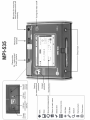
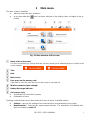
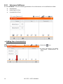
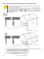
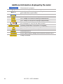
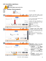
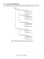
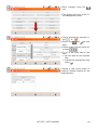
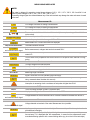
Fig. 2.1 Main elements of the screen
Name of the active menu
The fact of introducing a change that has not been saved yet is indicated by the * symbol in the
screen header.
Time
Date
Main screen
Free space on the memory card
If the card is not in the slot, the icon on the screen is crossed out.
Wireless network signal strength
Battery discharge indicator
Active menu help
Visualisation of connection systems
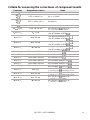
Explanation of icons
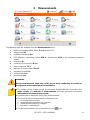
Touching a selected main menu item redirects to the sub-menu. Available options:
Settings – going to the settings of the main functions and parameters of the meter,
Measurements – Selecting the measurement function. The description of individual func-
tions is provided in section 3 ,

MPI-535 – USER MANUAL
8
Memory – viewing and managing the saved measurement results. A detailed description of
the function is provided in section 5,
Meter information
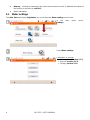
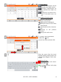
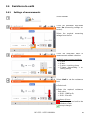
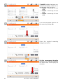
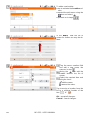
2.1 Meter settings
The date, time and display brightness can be set from the Meter settings screen level.
In the main menu select
Settings.
Select Meter settings
Parameters to change
Date and time (section 2.1.1)
Auto off (section 2.1.2)
Display (section 2.1.3)

MPI-535 – USER MANUAL
9
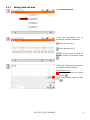
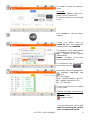
2.1.1 Setting date and time
Select Date and time.
Touch the appropriate icon to
modify the selected parameter:
value increase by 1,
value decrease by 1,
touching opens the field for
manual entering of the value (step
).
Delete the existing entry and enter
the required value manually.
Functions of icons
reject the changes and return
to step
accept changes and go to step

MPI-535 – USER MANUAL
10
Description of function icons
return to the previous screen
After touching the icon you
may be prompted to save or
reject changes (figure):
Yes – accept selection,
No – reject changes,
Cancel – cancel the action
saving changes
return to the main menu
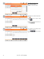
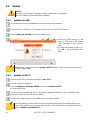
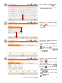
2.1.2 Automatic shutdown
Select Auto off.
Select the required option.
Description of function icons
return to the previous screen
After touching the icon you
may be prompted to save or
reject changes (figure):
Yes – accept selection,
No – reject changes,
Cancel – cancel the action
saving changes
return to the main menu

MPI-535 – USER MANUAL
11
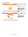
2.1.3 Display parameters
Select Display.
Parameters to change
time after which the display
enters the screen-saver mode
– select the required option
display brightness – move
the slider pointer
Description of function icons
return to the previous screen.
After touching the icon you
may be prompted to save or
reject changes:
Yes – accept selection,
No – reject changes,
Cancel – cancel the action
saving changes
return to the main menu

MPI-535 – USER MANUAL
12
2.2 Settings of measurements
From the Measurement settings menu it is possible to edit:
network parameters,
fuse definitions.
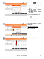
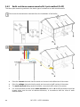
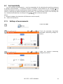
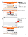
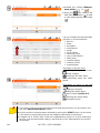
2.2.1 Sub-menu Measurement Settings
The option of Measurement settings consists of:
mains rated voltage,
network frequency,
manner of presentation of short-circuit loop result,
type of mains for the tested object,
system of units,
memory settings (auto-incrementing memory cells),
auto measurements timer,
RCD EV measurement standard.
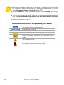
Before the measurements select the type of mains from which the tested object is powered.
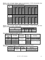
Then select the mains rated voltage Un (110/190 V, 115/200 V, 127/220 V, 220/380 V, 230/400 V or
240/415 V). This voltage value is used for calculating the values of prospective short-circuit current.
Determination of network frequency that is the source of potential interferences is necessary in
order to select a proper measuring signal frequency in resistance-to-earth measurements. This selec-
tion ensures optimum interference filtering. The meter is designed for filtration of interferences gener-
ated by 50 Hz and 60 Hz networks.
RCD EV measurement standard defines the parameters for measuring RCD protectors dedicat-
ed to the field of electromobility and photovoltaics.
Setting Autoincrementing as active ( ) causes each saved measurement (sec-
tion 5.3) to be placed in an automatically created new measurement point (section 5.2.2 step ).
Auto measurements timer determines the time interval of starting subsequent steps of the
measurement procedure.

MPI-535 – USER MANUAL
13
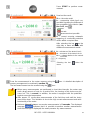
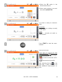
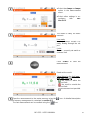
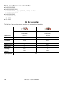
Expand the selection list using the icon.
Select the required parameter value.
Selection and modification options
Un voltage
110/190 V
115/200 V
127/220 V
220/380 V
230/400 V
240/415 V
Frequency fn
50 Hz
60 Hz
Fault loop measurement form
Ik – prospective short-circuit current
Zs – fault loop impedance
System type
TN/TT
IT
System of
units,
metric
imperial
Autoincrementing
enabled
disabled
Auto measurements
timer
Turn off
0…5 s
Description of function icons
return to the previous screen. After touching the
icon you may be prompted to save or reject
changes:
Yes – accept selection,
No – reject changes,
Cancel – cancel the action
saving changes
returning to the main menu

MPI-535 – USER MANUAL
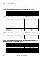
14
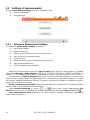
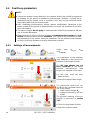
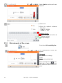
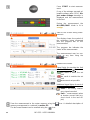
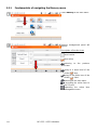
2.2.2 Sub-menu Edit fuses
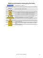
On the Fuse base screen the following parameters of circuit breakers can be defined and edited:
manufacturer,
model (type) of fuse,
characteristic of fuse.
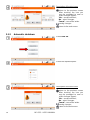
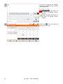
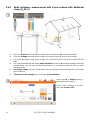
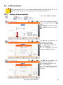
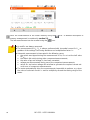
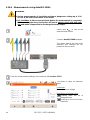
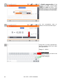
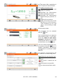
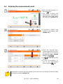
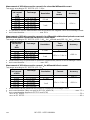
a. Adding fuse characteristics
Select the icon.
A menu will appear for adding
time-current characteristics of
fuses.

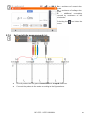
MPI-535 – USER MANUAL
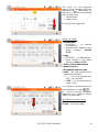
15
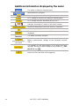
Available options
adding characteristics for the
selected fuse rated current.
removing characteristics for
the selected fuse rated cur-
rent.
pasting the set value for rec-
ords in the whole row or ta-
ble.
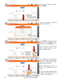
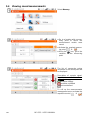
Description of function icons
inactive characteristic
active characteristic
adding a new characteristic
editing the name of the active
characteristic
removing the active character-
istic
returning to the previous
screen
going to the main menu
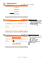
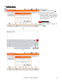
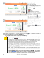
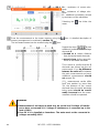
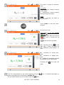
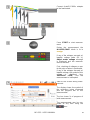
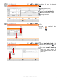
To create a new characteristic:
select the icon,
touch the name selection field.
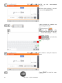
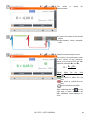
Enter the name from the touch
keypad (holding certain buttons for
a longer time triggers Polish char-
acters).
Functions of icons
rejecting changes and return-
ing to step
accepting changes and going
to step

MPI-535 – USER MANUAL
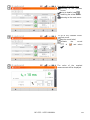
16
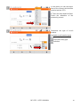
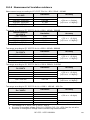
Description of function icons
Ok – accept the name
Cancel – cancel the action
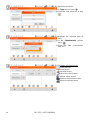
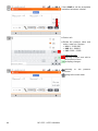
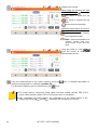
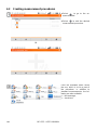
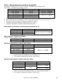
Activate the created characteris-
tic .
Add rated fuse current using
icon .
Editing fuse data proceed as in
steps .
To activate a row of data, select
any item in the row.
Icons will be activat-
ed.

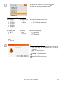
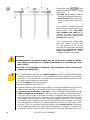
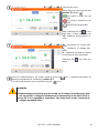
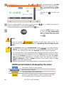
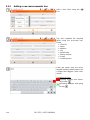
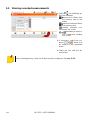
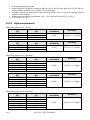
MPI-535 – USER MANUAL
17
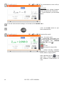
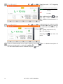
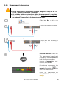
After selecting , the following
options are available:
parameter K – setting the
multiplication factor of fuse
rated current (parameter of
the time-current characteris-
tic),
fill row – copying K value to
the selected row,
fill table – copying K value to
all records.
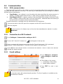
Touch the K parameter edit field.
Enter the parameter values as in
step .
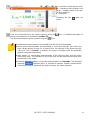
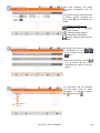
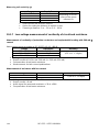
Description of function icons
Ok – accept selection
Cancel – cancel changes
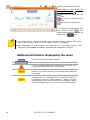
You will be prompted to conform
the selection.
Description of function icons
Yes – accept selection
No – reject changes
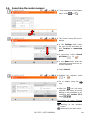
To change the contents of a se-
lected cell, touch it twice.

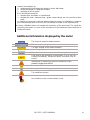
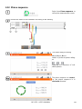
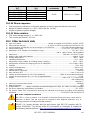
MPI-535 – USER MANUAL
18
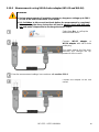
On-screen keyboard will appear.
Delete the existing entry and enter
the required one.
Functions of icons
reject changes and return to
the menu for adding charac-
teristics
accept changes and return to
the menu for adding charac-
teristics
Select the icon and return to
the fuse base menu.
Page is loading ...
Page is loading ...
Page is loading ...
Page is loading ...
Page is loading ...
Page is loading ...
Page is loading ...
Page is loading ...
Page is loading ...
Page is loading ...
Page is loading ...
Page is loading ...
Page is loading ...
Page is loading ...
Page is loading ...
Page is loading ...
Page is loading ...
Page is loading ...
Page is loading ...
Page is loading ...
Page is loading ...
Page is loading ...
Page is loading ...
Page is loading ...
Page is loading ...
Page is loading ...
Page is loading ...
Page is loading ...
Page is loading ...
Page is loading ...
Page is loading ...
Page is loading ...
Page is loading ...
Page is loading ...
Page is loading ...
Page is loading ...
Page is loading ...
Page is loading ...
Page is loading ...
Page is loading ...
Page is loading ...
Page is loading ...
Page is loading ...
Page is loading ...
Page is loading ...
Page is loading ...
Page is loading ...
Page is loading ...
Page is loading ...
Page is loading ...
Page is loading ...
Page is loading ...
Page is loading ...
Page is loading ...
Page is loading ...
Page is loading ...
Page is loading ...
Page is loading ...
Page is loading ...
Page is loading ...
Page is loading ...
Page is loading ...
Page is loading ...
Page is loading ...
Page is loading ...
Page is loading ...
Page is loading ...
Page is loading ...
Page is loading ...
Page is loading ...
Page is loading ...
Page is loading ...
Page is loading ...
Page is loading ...
Page is loading ...
Page is loading ...
Page is loading ...
Page is loading ...
Page is loading ...
Page is loading ...
Page is loading ...
Page is loading ...
Page is loading ...
Page is loading ...
Page is loading ...
Page is loading ...
Page is loading ...
Page is loading ...
Page is loading ...
Page is loading ...
Page is loading ...
Page is loading ...
Page is loading ...
Page is loading ...
Page is loading ...
Page is loading ...
Page is loading ...
Page is loading ...
Page is loading ...
Page is loading ...
Page is loading ...
Page is loading ...
Page is loading ...
Page is loading ...
Page is loading ...
Page is loading ...
Page is loading ...
Page is loading ...
Page is loading ...
Page is loading ...
Page is loading ...
Page is loading ...
Page is loading ...
Page is loading ...
Page is loading ...
Page is loading ...
Page is loading ...
Page is loading ...
Page is loading ...
Page is loading ...
Page is loading ...
Page is loading ...
Page is loading ...
Page is loading ...
Page is loading ...
Page is loading ...
Page is loading ...
Page is loading ...
-
 1
1
-
 2
2
-
 3
3
-
 4
4
-
 5
5
-
 6
6
-
 7
7
-
 8
8
-
 9
9
-
 10
10
-
 11
11
-
 12
12
-
 13
13
-
 14
14
-
 15
15
-
 16
16
-
 17
17
-
 18
18
-
 19
19
-
 20
20
-
 21
21
-
 22
22
-
 23
23
-
 24
24
-
 25
25
-
 26
26
-
 27
27
-
 28
28
-
 29
29
-
 30
30
-
 31
31
-
 32
32
-
 33
33
-
 34
34
-
 35
35
-
 36
36
-
 37
37
-
 38
38
-
 39
39
-
 40
40
-
 41
41
-
 42
42
-
 43
43
-
 44
44
-
 45
45
-
 46
46
-
 47
47
-
 48
48
-
 49
49
-
 50
50
-
 51
51
-
 52
52
-
 53
53
-
 54
54
-
 55
55
-
 56
56
-
 57
57
-
 58
58
-
 59
59
-
 60
60
-
 61
61
-
 62
62
-
 63
63
-
 64
64
-
 65
65
-
 66
66
-
 67
67
-
 68
68
-
 69
69
-
 70
70
-
 71
71
-
 72
72
-
 73
73
-
 74
74
-
 75
75
-
 76
76
-
 77
77
-
 78
78
-
 79
79
-
 80
80
-
 81
81
-
 82
82
-
 83
83
-
 84
84
-
 85
85
-
 86
86
-
 87
87
-
 88
88
-
 89
89
-
 90
90
-
 91
91
-
 92
92
-
 93
93
-
 94
94
-
 95
95
-
 96
96
-
 97
97
-
 98
98
-
 99
99
-
 100
100
-
 101
101
-
 102
102
-
 103
103
-
 104
104
-
 105
105
-
 106
106
-
 107
107
-
 108
108
-
 109
109
-
 110
110
-
 111
111
-
 112
112
-
 113
113
-
 114
114
-
 115
115
-
 116
116
-
 117
117
-
 118
118
-
 119
119
-
 120
120
-
 121
121
-
 122
122
-
 123
123
-
 124
124
-
 125
125
-
 126
126
-
 127
127
-
 128
128
-
 129
129
-
 130
130
-
 131
131
-
 132
132
-
 133
133
-
 134
134
-
 135
135
-
 136
136
-
 137
137
-
 138
138
-
 139
139
-
 140
140
-
 141
141
-
 142
142
-
 143
143
-
 144
144
-
 145
145
-
 146
146
-
 147
147
-
 148
148


Sonel MPI-535 User manual
- Category
- Measuring, testing & control
- Type
- User manual
Ask a question and I''ll find the answer in the document
Finding information in a document is now easier with AI
Related papers
-
Sonel MPI-536 User manual
-
-
-
-
Sonel MPI-530-IT Operating instructions
-
Sonel MPI-540 + EVSE-01 User manual
-
Sonel MIC-RS User manual
-
-
-
Other documents
-
Klein Tools ET600 User manual
-
3M COMBI521 Operating instructions
-
 Kewtech FC2000 User manual
-
Gossen MetraWatt PROFITEST MBASE+ Operating instructions
-
 Smart Sensor AR4105A User manual
-
-
Metronic MPI-DN-1 User manual
-
 METREL Eurotest 61557 User manual
-
Megger PAT300 Series User manual
-
Gossen MetraWatt PROFITEST PRIME Operating instructions


