Page is loading ...

Page 1 of 5
#796 CIRCULATING FAN KIT
DECEMBER 1999
INSTALLATION and OPERATING INSTRUCTIONS
Canadian and American Gas Association approved for use only with
VALOR LEGEND ULTRA MODEL 737X
1. DESCRIPTION OF SYSTEM
The Valor Legend Ultra Model 737 has been designed to accommodate the
installation of an air circulation fan. Operated by a hi/ lo/ off fan control and
a thermally actuated switch, it is designed to boost the natural convection
process through the heater, this may be a desirable feature dependent on the
fireplace location and room layout. The circulating fan may be installed
before the heater installation or as a retrofit at a later date.
2. ELECTRICAL REQUIREMENTS.
The fan kit requires a power supply of 120 Volts, 1 phase, 60 Hz. Full
load current is less than 1 amp.
This power supply must be installed and grounded in accordance with local
codes, or in the absence of local codes, with the current Canadian
Electrical Code CSA C22.1. or in the USA the National Electrical Code
ANSI/NFPA70 latest edition.
3. FAN KIT COMPONENTS
The complete #796CFK Kit contains the following:
• Fan /Motor c/w mounting plate,
wiring harness c/w thermal switch
and Molex connector.
• Hi/ Lo/ Off controller/ junction box
c/w Molex receptacle and 6’ cord
set.
• Right hand heat baffle
• Left hand heat baffle
• Control mounting bracket
• Screw and cable tie package

Page 2 of 5
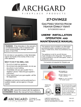
4. INSTALLATION
• Remove the heater inner front and front frame
in sequence and set aside. ( refer to fireplace
installation instructions)
• Remove the window, log set and brick set.
(refer to fireplace installation instructions)
• Shut off gas supply to the fireplace and
disconnect the gas line.
• Remove five screws securing the burner/
control assembly. The complete burner
assembly can now be withdrawn from the
fireplace by pulling it forward. (Fig. 1)
NOTE: Ensure that the metal base of the gas
fireplace enclosure is supported and anchored
to the floor (or bottom of masonry firebox).
If the metal base can flex up and down, it may
be a source of vibration noise when the
blower unit is installed. Now is the time to
correct this.
• Fit the blower unit by placing it into the rear
of the insert box and engage the back edge of
the mount into the raised cleats on the floor
of the box. Fasten the front of the mount to
the bracket using the machine screw
provided.(fig.2)
• Fit the right hand and left hand heat baffles to
the sides of the liner box using the screws
provided. (Fig.3)
• Route the wiring harness to the left side of
the liner box, through the cutout in the left
hand heat baffle, and fasten to the side wall
using the cable tie and the lower baffle securing
screw. (fig.4)
fig. 1
fig.2
fig.3
fig.4

Page 3 of 5
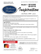
• Remove the metal between the two cutouts in
the side of the linerbox. (Fig.5)
• Secure the control mounting bracket to the
battery heat shield(see fig 6)
• Connect the Molex connector from the fan to
the control box, feed the cord set through the
left-hand side of the liner box, and then secure
the control box and the control heat shield to
the mounting bracket ( see fig 7)
• On the burner module, drill a 1/8” hole on the
burner tray approx 1” from the front.(see fig 8)
• Place the burner module back in engine and
secure the thermal switch ( see fig 9).
• If the fireplace is installed as an insert, route the
cord directly across the hearth on the left side,
away from the fireplace. Do not attempt to
route the cord behind, in front of or over the
liner box as damage to the cord may result in
an electrical hazard.
• Re assemble the fireplace.
• The fan and controls are factory tested to
ensure the fan operation but, with the control
box energized, check that the fan operates
correctly.The unit must be hot to do this.
fig.5
fig.6
fig.7
fig.8
fig.9

Page 4 of 5
5. OPERATION
The fan is designed for automatic operation using a thermal switch. To operate the
fan, press the switch to the left or right from the central off position, the position
marked with two dashes being the hi speed, one dash being the lo. The fan will not
run until the thermal switch is heated by the fireplace, this takes approx 5 to 10
mins. Should electrical power fail, the heater operation will remain unaffected. If the
fire is turned off, the fan will continue to operate until the thermal switch cools,
unless the switch is moved to the central, off position.
6. MAINTENANCE
This fan does not require any regular maintenance or lubrication, however periodic
cleaning of the fan compartment to remove household lint will help to maintain peak
fan performance.
This can be accessed by removing the bottom grill and using the crevice tool on the
end of a vacuum cleaner hose, carefully clean the bottom area of the fireplace
linerbox paying particular attention to the area under the burner box base.
Should the fan require additional servicing, it must be done by a qualified gas
appliance service person.
Over time, it may be useful to clean the fan blades themselves for dust
accumulation. To do this, it is necessary to remove the burner assembly. This must
be done by a qualified gas appliance service person.
Warning- Electrical Grounding Instructions
This appliance is equipped with a three-prong (grounded) plug for your protection
against shock hazard and should be plugged directly into a properly grounded
three-prong receptacle. Do not cut or remove the grounded prong from this plug.

Page 5 of 5
PLEASE LEAVE INSTALLATION AND OPERATING INSTRUCTIONS WITH THE
HOMEOWNER.
LIMITED WARRANTY POLICY
Miles Industries Ltd. warrants all components of the model 796 circulating fan kit for a period of one year from the
date of purchase against defects in materials or workmanship. This warranty covers only the cost of defective parts
and applies only to the original consumer purchaser. The replacement of defective parts by Miles Industries Ltd. will
be without charge during the warranty period. This warranty does not extend to (1) components damaged by
accident, neglect, misuse, abuse, alteration, negligence of others, including the installation thereof by unqualified
installers (2) the costs of removal, reinstallation or transportation of defective parts or (3) incidental or consequential
damages.
THIS WARRANTY IS EXPRESSLY IN LIEU OF ALL OTHER WARRANTIES, EXPRESSED OR IMPLIED,
INCLUDING THE WARRANTY OF MERCHANTABILITY OF FITNESS FOR PURPOSE AND OF ALL OTHER
OBLIGATIONS OR LIABILITIES. MILES INDUSTRIES LTD DOES NOT ASSUME, NOR HAS IT AUTHORIZED
ANY PERSON INCLUDING ITS SALES REPRESENTATIVES TO ASSUME FOR IT, ANY OTHER OBLIGATION OR
LIABILITY IN CONNECTION WITH THE SALE OR USE OF THE MODEL 796 CIRCULATING FAN KIT.
The model 796 circulating fan kit must be installed by a qualified installer in accordance with the instructions
furnished. The defective components should be returned at your expense to the dealer from where the product was
purchased or authorized service agent. Any components returned for warranty repair/replacement must be
accompanied by the sales invoice evidencing proof of purchase and date of purchase. Miles Industries Ltd. reserves
the right to repair and return any defective component.
Manufactured and distributed in Western Canada and USA by
Miles Industries Ltd.
829 West Third Street, North Vancouver B.C, CANADA, V7P 3K7
Ph. (604) 984-3496 Fax (604) 984-0246
Distributed in Eastern Canada by
Valtech Industries Ltd.
6660 Kennedy Road, Mississauga Ontario, L5T 2M9
Ph. (905) 795-0333 Fax. (905) 795- 0336
Copyright 1999
/