Page is loading ...


Operating Manual
Table of Contents
1.0 Introduction .................................................................................................. 3
1.1 About Your Product ........................................................................................................ 3
1.2 More Information ............................................................................................................ 3
2.0 Regulatory Information ................................................................................ 4
2.1 Declaration of Conformity ................................................................................................ 4
2.2 End User Licence Standard Conditions ............................................................................. 4
2.3 Safety Warnings and Exclusions ....................................................................................... 5
3.0 Getting Started ............................................................................................. 7
3.1 Checking the Accessory Kit ............................................................................................. 7
3.2 Optional Accessories ....................................................................................................... 7
3.3 Understanding the Parts and Controls .............................................................................. 8
3.4 Charging the Battery ....................................................................................................... 8
3.5 Preparing the AA Alkaline Battery Cassette ....................................................................... 9
3.6 Inserting and Removing the Battery ................................................................................11
3.7 Preparing to Handle the Thermal Imager ........................................................................12
4.0 Basic Operation ........................................................................................... 14
4.1 Power On and Off ..........................................................................................................14
4.2 Understanding the On-screen Display .............................................................................14
4.3 Universal Symbols and Meanings ....................................................................................15
4.4 Focus Range .................................................................................................................15
4.5 About ICE™ ..................................................................................................................16
4.6 Sensitivity Modes ...........................................................................................................16
4.7 Colour Reference Bar .....................................................................................................17
4.8 Direct Temperature Measurement ...................................................................................17
4.9 Ambient Temperature Measurement (Optional Feature) ...................................................18
5.0 Advanced Operation ................................................................................... 19
5.1 Main Menu ....................................................................................................................19
5.2 Zoom ............................................................................................................................20
5.3 Video Capture ...............................................................................................................20
5.4 Image Capture ..............................................................................................................21
5.5 Browsing Saved Images (Image Capture only) ................................................................22
5.6 Deleting Saved Files (Image Capture only) ......................................................................23
5.7 Selecting a Colour Palette ...............................................................................................24
5.8 Switching the Polarity ....................................................................................................25
5.9 Internal Transmitter .......................................................................................................25
5.10 Changing the Time & Date Settings ................................................................................26
6.0 Alternative Methods to View Live Thermal Images .................................... 27
6.1 Using an External Monitor to View a Live Thermal Image .................................................27
6.2 Using a PC to View Saved Files (Image Capture only) ......................................................27
6.3 Using a PC to Transfer Saved Files (Video Capture only) ..................................................28
7.0 Trouble Shooting ........................................................................................ 29
7.1 Power Source ................................................................................................................29
7.2 Imaging ........................................................................................................................29
7.3 Functions ......................................................................................................................29
8.0 Additional Information ............................................................................... 30
8.1 Maintenance Information ...............................................................................................30
© Copyright 2011, Infrared Systems Group Ltd. Page 2 of 34
While ISG Infrasys has taken care to ensure the accuracy of the information contained herein, it accepts no responsibility for
the consequences of any use thereof and reserves the right to change the specification of goods without notice.

Operating Manual
8.2 Warranty Agreement......................................................................................................30
8.3 Technical Specifications .................................................................................................32
1.0 Introduction
1.1 About Your Product
Thank you for purchasing your brand new, high-specification thermal imaging product from Infrared
Systems Group Ltd. Your product has been designed and manufactured in our technical facility, where
it has been tested to meet the requirements of the ISO 9001 quality standards.
All information provided in this and any other documentation enclosed with your product is correct at
time of going to print and is subject to change without notification. For the purposes of these
documents, Infrared Systems Group Ltd. is sometimes referred to as ‘ISG INFRASYS’. ISG Infrasys is a
trading name of Infrared Systems Group Ltd.
These documents use an ‘SD’ variant product to depict it’s usage and operation. This may differ from
your purchased product, however the functionality is exactly the same, unless otherwise stated.
We strongly recommend that you read through the Regulatory Information in the next section of this
Operating Manual prior to using your thermal imaging product for the first time.
1.2 More Information
Should you have any queries with regard to this or any other ISG INFRASYS thermal imaging product,
please contact our Customer Services team:
Infrared Systems Group Ltd.
Unit 14
Repton Court
Repton Close
Basildon
Essex
SS13 1LN
United Kingdom
+44 (0) 1268 52 77 00
+44 (0) 1268 52 77 99
www.isgfire.co.uk
© Copyright 2011, Infrared Systems Group Ltd. Page 3 of 34
While ISG Infrasys has taken care to ensure the accuracy of the information contained herein, it accepts no responsibility for
the consequences of any use thereof and reserves the right to change the specification of goods without notice.

Operating Manual
2.0 Regulatory Information
2.1 Declaration of Conformity
The EC Declaration of Conformity for your model of ISG INFRASYS thermal imager is supplied as a
separate document on your Product Documents CD-ROM.
Safe Disposal
This symbol indicates the requirement for a separate waste collection for electronic
equipment, batteries and accumulators. All ISG INFRASYS products displaying this
symbol must be disposed of or recycled in accordance with EU Directives 2002/96/EC
(WEEE) and 2006/66/EC (batteries).
This procedure is described as follows:
Upon reaching the end of its useful life, the thermal imager must be returned to Infrared Systems
Group Ltd. in the United Kingdom for suitable disposal under the WEEE directives. ISG INFRASYS will
arrange collection at our expense, when notified that the item is no longer required.
Accessory items requiring safe disposal, including battery packs, can be disposed of locally under the
regulatory directives of your local authority.
Export Obligations
The technology utilised in ISG INFRASYS thermal imagers is subject to export control regulation by
the Government of the UK. Where an export licence applies, once obtained by ISG INFRASYS on
behalf of the customer, all parties must strictly adhere to the terms and conditions pertaining to that
licence. Otherwise, ISG INFRASYS’s authorisation to provide maintenance and further support may be
suspended or withdrawn and criminal charges may result against both ISG INFRASYS and the
customer.
Where an export licence applies, a copy of the specific terms and conditions pertaining to this licence
is enclosed with your product – all users are encouraged to become familiar with them. As an
indicative (but not exhaustive) guide, your ISG INFRASYS thermal imager’s End User Licence Standard
Conditions are reproduced in the next section.
2.2 End User Licence Standard Conditions
1) This ISG INFRASYS thermal imager, (the “item”), is licensed by the UK Department for
Business, Enterprise & Regulatory Reform for export to Fire, Search and Rescue end users
only, solely for use in firefighting, search and rescue operations within the sovereign state
of the end user to whom it is originally exported. The export licence document, including all
its terms and conditions, carries the force of law under the jurisdiction of the United
Kingdom.
2) The end-user must maintain the item in their possession at all times and is responsible for
its security against theft, loss, unauthorised access or use.
3) No loan or temporary surrender of the item is authorised.
4) No resale, donation, transfer or disposal by other means of the item is authorised.
Therefore, when the item reaches the end of its service life, it must be returned to Infrared
Systems Group Ltd. ISG INFRASYS will arrange collection at our expense, when notified
that the item is no longer required.
© Copyright 2011, Infrared Systems Group Ltd. Page 4 of 34
While ISG Infrasys has taken care to ensure the accuracy of the information contained herein, it accepts no responsibility for
the consequences of any use thereof and reserves the right to change the specification of goods without notice.

Operating Manual
5) Maintenance of the item is limited to routine preventative maintenance and installation of
field replacement parts only. Disassembly and/or repair of electrical/mechanical assemblies
must only be performed by the manufacturer’s designated service centres.
6) Sale, resale or loan of the item for temporary purposes such as demonstration, rental or
lease equipment is prohibited.
7) If the item is lost, stolen or destroyed, or unauthorised people have access to it, this must
be reported to Infrared Systems Group Ltd. within 21 days. The report must include a
description of the incident, to include as appropriate:
Who had physical possession of the item
What is being done to recover the item
Police incident report number
Steps taken to prevent another such event
If unauthorised personnel had access to the item, who allowed this and what has
been done to avoid recurrence
8) The end-user must provide a letter of acknowledgement and acceptance of the export
licence to ISG INFRASYS prior to shipment of the item.
2.3 Safety Warnings and Exclusions
All users of ISG INFRASYS thermal imagers must read the following safety warnings and exclusions
carefully.
1) ISG INFRASYS thermal imagers must only be used by personnel familiar with the usage
and limitations of a thermal imaging device, including a general understanding of thermal
images and how they are interpreted. It is recommended that the user has gained
experience with its usage in simulated emergency conditions, such as a controlled live burn
situation. Usage of the ISG INFRASYS thermal imager by unauthorised, unfamiliar or
untrained users in a hazardous atmosphere may result in injury or death.
2) The ISG INFRASYS thermal imager is not life support equipment and should not be used as
such.
3) The ISG INFRASYS thermal imager provides a thermal image in normal vision-impairing
conditions and is designed to augment any of your existing Standard Operating Procedures.
Failure to follow Standard Operating Procedures in a hazardous atmosphere may result in
disorientation, injury or death, in the unlikely event that the equipment should fail.
4) Always perform a visual check on the equipment prior to use to validate that it has not
been damaged or degraded.
5) Never use the ISG INFRASYS thermal imager as the sole source of navigation. If system
failure occurs, you may become disoriented or lost in a hostile environment, which could
result in injury or death.
6) The ISG INFRASYS thermal imager is a complex, electro-optical piece of equipment and,
just like any other piece of machinery or electronic system, is subject to potential failures.
Should a failure occur, the user will no longer have access to the thermal images provided
by the thermal imager. Tactical usage of this equipment must not deviate from Standard
Operating Procedures used by personnel who do not have the benefit of the equipment.
© Copyright 2011, Infrared Systems Group Ltd. Page 5 of 34
While ISG Infrasys has taken care to ensure the accuracy of the information contained herein, it accepts no responsibility for
the consequences of any use thereof and reserves the right to change the specification of goods without notice.

Operating Manual
7) While every effort has been made to ensure that your ISG INFRASYS thermal imager is
both tough and reliable, the thermal imager is a sophisticated electro-optical system that
will fail if it is abused or exposed to environments beyond its design envelope.
8) Repeated exposure to high temperature environments without adequate periods for the
unit to self-cool may result in degradation or loss of the thermal image, or damage to the
internal components. Be sure to allow adequate cool-down periods between high
temperature exposures.
9) The ISG INFRASYS thermal imager will not provide images through glass, water, or shiny
objects. These surfaces act like reflective mirrors to the system.
10) The ISG INFRASYS thermal imager will not provide thermal images underwater.
11) Batteries supplied with the ISG INFRASYS thermal imager have been selected for specific
performance values. Replacement batteries must be obtained ONLY from an authorised ISG
INFRASYS service centre. In addition:
Never try to dispose of the battery pack by burning or through exposure to a
heating device such as a microwave oven – it could explode and cause injury.
Never try to disassemble, repair or otherwise tamper with a battery pack.
Never short-circuit the battery pack by contacting the terminals with a metal object.
Never puncture the battery pack with a sharp object or strike with a hammer or
other object.
12) Users should be conscious of the battery life. Only enter a hazardous environment when a
full battery charge is indicated on the battery charge indicator.
13) Failure to exit a hostile environment immediately on observation of the low battery warning
may result in system failure in a hostile environment, which could result in injury or death.
14) The ISG INFRASYS thermal imager is not rated as "Intrinsically Safe". Do not use the
system in environments or atmospheres where static or a spark could cause explosion.
15) The ISG INFRASYS thermal imager must be serviced only by authorised personnel. The
thermal imager contains high voltage components and therefore, the user should never
remove the cover due to risk of shock.
© Copyright 2011, Infrared Systems Group Ltd. Page 6 of 34
While ISG Infrasys has taken care to ensure the accuracy of the information contained herein, it accepts no responsibility for
the consequences of any use thereof and reserves the right to change the specification of goods without notice.

Operating Manual
3.0 Getting Started
3.1 Checking the Accessory Kit
Dependant on your order, your
thermal imager is supplied with
one of the accessory kits shown.
We recommend that you
regularly check each standard
accessory is accounted for, and
is in good working order prior to
use.
If you require more information
on any standard accessory,
please visit our website at
www.isgfire.co.uk.
3.2 Optional Accessories
Dependant on your order, you may also have some of the following optional accessories included in
your accessory kit. We recommend that you regularly check that each optional accessory is accounted
for, and is in good working order prior to use.
Optional
Optional
Optional
Optional
Optional
Optional
If you require more information on any optional accessory, please visit our website at
www.isgfire.co.uk.
Kit 1
X1
Kit 2
X1
X2
X2
X1
X1
X1
X1
X1
X1
X1
© Copyright 2011, Infrared Systems Group Ltd. Page 7 of 34
While ISG Infrasys has taken care to ensure the accuracy of the information contained herein, it accepts no responsibility for
the consequences of any use thereof and reserves the right to change the specification of goods without notice.

Operating Manual
3.3 Understanding the Parts and Controls
1) Universal Viewing System (not available on
‘K’ models)
2) Hand straps and pads
3) Lens window
4) Battery compartment (including battery
contacts, and thermal imager identification
and warning label)
5) Mounting bracket and lanyard ‘D’ ring
6) LCD Display
7) LED
8) Red button
9) BNC connector and dust cover
10) Yellow button
3.4 Charging the Battery
Information
All batteries are fully charged on leaving the factory and are ready for immediate use.
WARNING
Do not expose the battery charger unit and/or power adapter to rain or moisture.
Do not attempt to use a charging device to charge a non-ISG INFRASYS approved battery.
To install your VMC or VMTC battery charger, please refer to the installation guide enclosed.
Always check the charging device is in good working order before each use.
© Copyright 2011, Infrared Systems Group Ltd. Page 8 of 34
While ISG Infrasys has taken care to ensure the accuracy of the information contained herein, it accepts no responsibility for
the consequences of any use thereof and reserves the right to change the specification of goods without notice.

Operating Manual
Using a Desktop Charger
1) Connect mains adaptor to charger, then
connect to mains power outlet and switch
on power.
2) Red LED flashes - in ‘Standby Mode’
3) Insert the battery into the charger
4) Green LED flashes - battery is charging
5) Green LED steady - battery is charged
Using a Vehicle Mount Charger (VMC)
1) Install device (see installation guide)
2) Insert thermal imager, with external battery
contacts facing in towards the charger, into
the charging station, ensuring the locator
pins are correctly aligned, and push until
the thermal imager ‘clicks’ into place
3) Green LED steady - battery is charged
4) Push the ‘Quick-Release’ lever down to
release the thermal imager.
Using a Vehicle Mount Twin-Charger (VMTC)
1) Install device (see installation guide)
2) Insert thermal imager and/or battery, with
external battery contacts facing in towards
the charger, into the appropriate charging
station and secure using the strap(s).
3) Green LED steady - battery is charged.
Undo strap(s) and remove.
3.5 Preparing the AA Alkaline Battery Cassette
Information
It is recommended that the positive (+) end of each AA battery cell is inserted into the cassette
first, before pushing the negative (-) end into position.
© Copyright 2011, Infrared Systems Group Ltd. Page 9 of 34
While ISG Infrasys has taken care to ensure the accuracy of the information contained herein, it accepts no responsibility for
the consequences of any use thereof and reserves the right to change the specification of goods without notice.

Operating Manual
1) Depress the release button and slide out
the inner compartment.
2) Insert 10x AA Alkaline batteries into the
inner compartment, ensuring the positive
(+) and negative (-) orientation is correct.
3) Depress the button, replace the inner
cassette into the outer cassette and release
to lock.
© Copyright 2011, Infrared Systems Group Ltd. Page 10 of 34
While ISG Infrasys has taken care to ensure the accuracy of the information contained herein, it accepts no responsibility for
the consequences of any use thereof and reserves the right to change the specification of goods without notice.

Operating Manual
3.6 Inserting and Removing the Battery
Inserting the Battery
1) Insert the battery into the battery
compartment.
2) Push until the battery ‘clicks’ into place.
Removing the Battery
1) Simultaneously depress the release catches
on either side of the battery.
2) Slide the battery out of the compartment.
© Copyright 2011, Infrared Systems Group Ltd. Page 11 of 34
While ISG Infrasys has taken care to ensure the accuracy of the information contained herein, it accepts no responsibility for
the consequences of any use thereof and reserves the right to change the specification of goods without notice.

Operating Manual
3.7 Preparing to Handle the Thermal Imager
Holding the Thermal Imager
Insert your hand through the hand strap as shown.
Adjusting the Hand Strap
1) Peel back the velcro hand pad and strap
and adjust as required.
2) Refasten the strap and velcro hand pad.
Attaching a Lanyard
1) Push open the clip on the lanyard.
2) Insert clip round the ‘D’ ring and release.
© Copyright 2011, Infrared Systems Group Ltd. Page 12 of 34
While ISG Infrasys has taken care to ensure the accuracy of the information contained herein, it accepts no responsibility for
the consequences of any use thereof and reserves the right to change the specification of goods without notice.

Operating Manual
Attaching a Grip Handle
1) Align the locator pins on the grip with the
locator holes on the mounting bracket and
then push the grip into the mounting
bracket
2) Slide the grip towards the rear of the
thermal imager until the grip ‘clicks’ into
place.
Removing a Grip Handle
3) Push the button on the grip downwards
and slide the grip towards the front of the
thermal imager until it is released.
© Copyright 2011, Infrared Systems Group Ltd. Page 13 of 34
While ISG Infrasys has taken care to ensure the accuracy of the information contained herein, it accepts no responsibility for
the consequences of any use thereof and reserves the right to change the specification of goods without notice.

Operating Manual
4.0 Basic Operation
4.1 Power On and Off
WARNING
Always fit a fully charged battery prior to use in an emergency operation.
Never disconnect the battery without undertaking the turn off procedure.
Power On
1) Press the Red button.
2) LED lights continuously and start-up
screen is displayed for 10 seconds
(approx.), signifying that the start-up
sequence has been initiated.
3) Live thermal image is displayed with a
DTM readout given in the top right
corner to signify the thermal imager is
operating in Normal Imaging Mode.
Power Off
4) Press and hold the Red button.
5) Release when the desired action
symbol is displayed:
Power Off
Abort Power Off
4.2 Understanding the On-screen Display
1) Time & Date (if displayed)
2) Crosshair
3) LED
4) DTM readout
5) Colour Reference Bar
6) Battery Bar
© Copyright 2011, Infrared Systems Group Ltd. Page 14 of 34
While ISG Infrasys has taken care to ensure the accuracy of the information contained herein, it accepts no responsibility for
the consequences of any use thereof and reserves the right to change the specification of goods without notice.

Operating Manual
4.3 Universal Symbols and Meanings
This product uses Universal Symbols to aid all user’s interpretation of the information being displayed.
This list briefly describes the meaning of each symbol that may be displayed when using this product.
1) Battery 100%
2) Battery 75%
3) Battery 50%
4) Battery 25%
5) Battery <5% (flashing)
6) Power
7) Exit
8) X2 Zoom
9) X4 Zoom
10) Capture
11) Record (optional)
12) Wait
13) Browse Menu
14) Colour Palette Select
15) Polarity Switch White Hot
16) Polarity Switch Black Hot
17) Transmitter (optional)
18) Settings Menu
19) View File
20) Previous Page
21) Previous File
22) Next File
23) Next Page
24) Delete File
25) Delete All Files
26) Change the Day
27) Change the Month
28) Change the Year
29) Change the Hour
30) Change the Minute
31) Change the Second
32) Change Display Options
4.4 Focus Range
This product uses an automatic focus feature that ensures the user can always receive the best
detailed image at all times.
© Copyright 2011, Infrared Systems Group Ltd. Page 15 of 34
While ISG Infrasys has taken care to ensure the accuracy of the information contained herein, it accepts no responsibility for
the consequences of any use thereof and reserves the right to change the specification of goods without notice.

Operating Manual
This product has an approximate focus range of
1.5 metres to infinity (∞).
This means that objects that are imaged from
less than 1.5 metres away may appear slightly
blurred on the display.
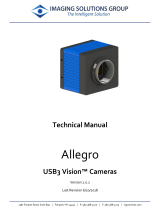
4.5 About ICE™
ICE
™
(Intelligent Contrast Enhancement) is a
patented* innovation from ISG INFRASYS. This
technology operates to automatically enhance
background contrast when viewing extremely hot
objects.
This improves visibility for the user as hot objects and
cooler surroundings are clearly visible simultaneously.
The extra information is vital when viewing extreme
temperatures in 1000+ Mode and increases the user’s
effectiveness, as well as their safety.
This image shows how ICETM improves visibility in
practice.
*Patent No. GB2435977
4.6 Sensitivity Modes
The ICETM system thermal imager incorporates two distinct sensitivity modes and selects the
appropriate mode automatically by analysing the thermal characteristics of the scene.
Information
When the thermal imager switches sensitivity modes, a momentary interruption of the displayed
image may be experienced.
© Copyright 2011, Infrared Systems Group Ltd. Page 16 of 34
While ISG Infrasys has taken care to ensure the accuracy of the information contained herein, it accepts no responsibility for
the consequences of any use thereof and reserves the right to change the specification of goods without notice.

Operating Manual
Normal Mode
‘Normal Mode’ is automatically selected when viewing
low to medium ambient temperature scenes and/or
when any hot objects in the scene are either below
approximately 300 °C, or are very small.
In this mode the thermal imager’s sensitivity is
optimised to maximise the clarity of the lower-
temperature parts of the scene, enabling crystal-clear
imaging of the ambient scene as well as displaying
small, localised hotspots up to 500 oC without
saturation.
1000+ Mode
‘1000+ Mode’ is automatically selected when viewing
extreme heat conditions, for example, in flash over
situations or other extreme emergency situations
where safety could be compromised.
In this mode the dynamic range is set to maximum to
provide clear imaging of scene temperatures in excess
of 1000 °C without saturation, designed to allow easy
analysis of structures and other hot/burning materials
while retaining excellent visibility of low-temperature
background detail to facilitate rapid egress.
4.7 Colour Reference Bar
The graduated scale colour palette provides a visual
indication of the range of scene temperatures
detected, enabling rapid recognition of hot spots.
The Colour Reference Bar (right) is displayed on the
right-hand edge of the screen and provides a point of
reference for the user to quickly identify the different
temperature ranges in the scene.
4.8 Direct Temperature Measurement
The Direct Temperature Measurement (DTM) feature gives a temperature readout of a fixed point on
the screen. The DTM feature is accurate to ±5 °C for 0 °C - 100 °C, and ±10% for 101 °C - 1000 °C.
Information
The measured temperature is based on an assumed target emissivity of 0.95.
The measurement indicated is not a measure of air temperature.
Unless otherwise specified at the time of order, the unit of measurement (i.e Celsius or
Fahrenheit) is preset at the factory to the normal standard for the designated country.
In order to obtain an accurate measurement of a hot object in a scene, the thermal imager may
switch between different sensitivity modes. This is completely normal.
© Copyright 2011, Infrared Systems Group Ltd. Page 17 of 34
While ISG Infrasys has taken care to ensure the accuracy of the information contained herein, it accepts no responsibility for
the consequences of any use thereof and reserves the right to change the specification of goods without notice.

Operating Manual
Operate DTM
1) Aim the crosshair directly over the object
to be measured.
2) Read the temperature.
4.9 Ambient Temperature Measurement (Optional Feature)
The Ambient Temperature Measurement (ATM) operates using a sensor located underneath the
battery compartment on the mounting bracket of the product.
Information
Unless specified otherwise at the time of order, the unit of measurement, in terms of degrees
Celsius or Fahrenheit, is preset at the factory to the normal standard for the designated country.
WARNING
The measurement indicated does not accurately reflect the user’s immediate environment, and
refers specifically to the ATM of the environment within a 50 cm radius of the product.
Additional factors can affect the accuracy of the ATM readout and therefore the feature should
only be used as a guide, and should never allow the user to deviate from their standard
operating procedures.
The Ambient Temperature Measurement (ATM)
feature gives the user a readout of the ambient air
temperature of the immediate surrounding
environment to the product. The ATM feature operates
in 5 °C increments and is accurate to ±5 °C within a
50 cm radius of the product.
1) ATM temperature readout.
© Copyright 2011, Infrared Systems Group Ltd. Page 18 of 34
While ISG Infrasys has taken care to ensure the accuracy of the information contained herein, it accepts no responsibility for
the consequences of any use thereof and reserves the right to change the specification of goods without notice.

Operating Manual
5.0 Advanced Operation
5.1 Main Menu
Information
Upon entering any level of the ‘menu structure’, the thermal imager will revert to Normal
Imaging Mode if no action is executed by the user for 10 seconds.
The executable action in the menu is identified by a black background.
To Enter the Main Menu
1) From Normal Imaging Mode, or when in
Zoom, press and hold the Yellow button for
approximately 3 seconds.
2) The thermal imager enters the Main Menu
and automatically highlights the first
symbol.
To Navigate Through the Menu
1) Press the Red button to highlight the next
action.
To Execute an Action in the Menu
2) Press the Yellow button to execute the
highlighted action.
To Return to the Previous Menu
3) Press the Red button and the Yellow button
together. The Exit symbol is displayed and
the thermal imager returns to the previous
menu.
To Exit All Menus
4) Press and hold the Red button and the
Yellow button together for 3 seconds
(approx.). The Exit symbol is displayed and
the thermal imager returns to Normal
Imaging Mode.
© Copyright 2011, Infrared Systems Group Ltd. Page 19 of 34
While ISG Infrasys has taken care to ensure the accuracy of the information contained herein, it accepts no responsibility for
the consequences of any use thereof and reserves the right to change the specification of goods without notice.

Operating Manual
5.2 Zoom
Information
X4 Zoom is only available on products that operate with a high-resolution detector. Where X4
Zoom is not available, please disregard points 3 and 4 in the instructions below.
Zoom On
1) From Normal Imaging Mode, press the Red
button.
2) The live image is magnified by a factor of 2
and the X2 Zoom symbol is displayed.
3) To operate with X4 Zoom, press the Red
button again.
4) The live image is magnified by a factor of 4
and the X4 Zoom symbol is displayed.
Zoom Off
5) Press the Red button to exit.
5.3 Video Capture
Information
The Video Capture feature is optional and therefore the following instructions may not apply.
Video Capture can be used when in Normal Imaging Mode or when using the Zoom feature.
© Copyright 2011, Infrared Systems Group Ltd. Page 20 of 34
While ISG Infrasys has taken care to ensure the accuracy of the information contained herein, it accepts no responsibility for
the consequences of any use thereof and reserves the right to change the specification of goods without notice.
/