Page is loading ...

Your energy. Optimized.
Heat Recovery
DM
UK | Read and save these instructions!

Project:
Material:
Date:
Rev.:
Title:
Rev. No.: Ref.:
Format:
Weight:
Approved:
Draw. No.:
Scale:
DM400
DM400, komplet
20-12-2017
bni
DS/EN 22768 m
Unless otherwise specified tolerances are after
A
123,769 kg
1:10
Sheet:
1 of 2
A3

Your energy. Optimized.
Heat Recovery | Damper Motor
Content
Product information 7
Scope of supply 7
Accessories and spare parts 8
Warranty 9
Technical specications 10
Mechanical installation 13
Placement and orientation 14
Flue gas direction 15
Damper dicretion 16
Mounting 18
Mounting points 19
Electrical installation 21
Wiring Diagram/Electrical Connection of Damper Motor 21
Installation and Placement of Belimo Motor Unit 22
Installation/adjustment with Belimo motor type NFA 10 Nm 23
Installation/adjustment with Belimo motor type NF24A-SZ 28
Startup and conguration 29
System startup 29
Operating Conditions on Flue Gas Side 29
Maintenance and troubleshooting 30
Troubleshooting 30
UK Conformity Assessed 31
Declaration of Conformity 32

Disposal
Electrical and electronic equipment (EEE) often contain materials, components and substances
that may harm the environment or be hazardous to your health. Products (WEEE) marked with
the ‘crossed-out wheeled bin’ symbol should be disposed of separately from other waste at the
end of its life. Though legislation may differ from country to country we strongly advise that
electrical and electronic waste is separated from other waste and disposed of according to
national legislation to protect the environment and personnel that may come into contact with
waste.
How to use this manual
This manual has been prepared based on the specific product and
contains relevant technical information and installations guides.
Accessories and spare parts are not covered by this manual.
Please refer to the individual manuals of these components.
This installation manual does not contain any system design documentation.
Failure to observe instructions marked with a danger symbol
may result in personal injury and/or damage to the product.
Errors and omissions excepted.
Symbols
The following symbols may be used in the manual
to draw attention to danger or risk of personal
injury or damage to the product.
General prohibition
Failure to observe instructions marked with the prohibited
symbol may result in extreme danger or serious personal injury.
General warning
Failure to observe instructions marked with a danger symbol
may result in personal injury and/or damage to the product.
General attention
Marks a dangerous situation that, in the worst-case scenario,
can cause serious personal injury or significant damage to the product.
Electricity hazard/High Voltage
Marks a situation in which caution is advised due to the risk of high voltage electric
shock which can cause serious personal injury or significant damage to the product.
Connect an earth terminal to the ground
Failure to observe instructions marked with a danger symbol
may result in personal injury and/or damage to the product.
Permitted and approved
Permitted and approved method of installation.
Prohibited and not approved
Prohibited and not approved method of installation.
UK | 5

Warning
To minimise the risk of fire, electric shock, personal injury
and/or damage to the product please observe the following:
• Please always read the manual and only use the product in accordance with the
manufacturer’s instructions. If in doubt, contact one of the Exodraft specialized dealers.
• All installations must be carried out by properly qualifi ed personnel in accordance with
national legislation and regulations.
• Prior to servicing the product, the heat source must be shut off and cooled down.
• Please ensure that the heat source is not turned back on inadvertently.
• A safety thermostat (ST110) and/or safety valve must be installed and connected to the
burner, ensuring disconnection in case of excessive temperatures. The switch must comply
with EN 14597.
Your energy. Optimized.
6 | UK

UK | 7
3112028_DM_UK
Warning
To minimise the risk of fire, electric shock, personal injury
and/or damage to the product please observe the following:
• Please always read the manual and only use the product in accordance with the
manufacturer’s instructions. If in doubt, contact one of the Exodraft specialized dealers.
• All installations must be carried out by properly qualifi ed personnel in accordance with
national legislation and regulations.
• Prior to servicing the product, the heat source must be shut off and cooled down.
• Please ensure that the heat source is not turned back on inadvertently.
• A safety thermostat (ST110) and/or safety valve must be installed and connected to the
burner, ensuring disconnection in case of excessive temperatures. The switch must comply
with EN 14597.
Your energy. Optimized.
Product information
The exodraft Damper Motor is used in exodraft exhaust system solutions for the protection or control of
inow of hot ue gas to Basic Plate heat recovery devices.
A damper motor is used primarily for larger boiler systems, industrial processing plants, or commercial
systems.
An integrated electric motor opens and closes the ue. Two types: on/off or modulating motor.
Power supply and start/stop signal come from an external exodraft control, and thus is not part of the
Damper Motor.
The Damper Motor has a safety feature causing it to enter safety mode automatically in case of power
failure.
All parts affected by ue gas are made of stainless steel EN 1.4404.
All exterior parts are made of stainless steel EN 1.4301.
The Damper Motors limitations
• Max. temperatur 600°C.
• The Damper Motor is not to be used as a draining point in an exhaust system.
• As a rule, the Damper Motor is only for indoor installation.
• Installation outside requires extra shielding.
• Flue gas / process air must be of a quality (particle free) that will not, over time, cause the
damper to be lled with residue that can affect the function of the damper.
To nd out more about heat recovery visit www.exodraft.com
Scope of supply
• Exodraft Damper Motor
• Installation manual and user instructions
• Pallet*
• Straps*
• Screws*
• Transportation safety brackets*
*For transportation only. Be aware to disconnect these parts before installation.

8 | UK
Your energy. Optimized.
Accessories and spare parts
The table below shows the spare parts available for the Damper Motor models.
Spare parts
3201081 Damper motor NFA 10 Nm
3201078 Damper motor NF24A-SZ 10 Nm
*This manual does not describe the specic use of spare parts. We refer to the separate manuals for such components.
For more details contact your Exodraft dealer.

UK | 9
3112028_DM_UK
Warranty
All Exodraft products are covered by a 2-year guarantee as per European consumer rights legislation. For
some countries an extended period of guarantee may apply depending on either national legislation or
other clearly stipulated conditions. Customer complaints must be handled by a specialised dealer or
wholesaler (preferably where the Exodraft product has been bought originally). An updated list of Exodraft
specialised dealers can be found on our website for the country in question.
Exodraft products must always be installed by properly qualied personnel. Exodraft reserves the right to
change these guidelines without prior notice.
The warranty and liability does not cover instances regarding personal injury or damage to property or the
product that can be ascribed to one or more of the following causes:
• Failure to follow this installation and operation manual
• Incorrect installation, start-up, maintenance or servicing
• Improper repairs
• Unauthorised structural modications made to the product
• Installation of additional components that have not been tested/approved with the product
• Any damage resulting from continued use of the product despite an evident defect
• Failure to use original spareparts and accessories
• Failure to use the product as intended
• Exceeding or failure to meet the limit values in the technical data
• Force majeure

10 | UK
Your energy. Optimized.
Technical specications
Basic types
Exodraft
item number
Type
(Damper Motor) Description Motor type Inlet Ø
exterior [mm]
Outlet Ø
interior [mm]
8004500 DM350
On/off damper with motor
Standard pipe connection
dimensions
Max 600 °C
Damper motor
NFA 10 Nm 350,5 351,2
8004501 DM350
Modulating damper with
motor Standard pipe con-
nection dimensions
Max 600 °C
Damper motor
NF24A-SZ 10
Nm
350,5 351,2
8004600 DM400
On/off damper with motor
Standard pipe connection
dimensions
Max 600 °C
Damper motor
NFA 10 Nm 400,5 401,2
8004601 DM400
Modulating damper with
motor Standard pipe con-
nection dimensions
Max 600 °C
Damper motor
NF24A-SZ 10
Nm
400,5 401,2
8004700 DM500
On/off damper with motor
Standard pipe connection
dimensions
Max 600 °C
Damper motor
NFA 10 Nm 500,5 501,2
8004701 DM500
Modulating damper with
motor Standard pipe con-
nection dimensions
Max 600 °C
Damper motor
NF24A-SZ 10
Nm
500,5 501,2

UK | 11
3112028_DM_UK
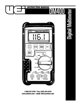
Standard components
1Danger/Caution sign
2 Nameplate
3Damper motor
4M12 thread with lifting
bolts for mounting
5Housing
6Inlet
7Damper aps
8 Outlet (behind the product)
Project:
Material:
Date:
Rev.:
Title:
Rev. No.: Ref.:
Format:
Weight:
Approved:
Draw. No.:
Scale:
DM500
DM500, komplet
bni
DS/EN 22768 m
Unless otherwise specified tolerances are after
A
123,769 kg
1:6,67
Sheet: 1 of 2
A3
8
3
5
6
1
8
7
4
2

12 | UK
Your energy. Optimized.
Technical data
Model Dimensions [mm]
A B C* D E* F G H** I J K L M
DM350 563,4 424,4 347,5 347,5 60 56 696,4 755,1 638,2 351,5 300 350,5 562
DM400 563,4 424,4 347,5 347,5 60 56 696,4 755,1 638,2 401,5 300 400,5 562
DM500 563,4 424,4 347,5 347,5 60 56 696,4 755,1 638,2 501,5 300 500,5 562
*Species inside sleeve dimensions
**Species outside adapter dimensions
I
G
H
F
D C
E
B
A
K
M
L
J

UK | 13
3112028_DM_UK
Mechanical installation
Exodraft products must always be installed by properly qualied personnel.
These instructions, applicable standards and relevant safety procedures from the manufacturer must be
followed and at the same time the ofcial provisions in force in the country, where the product is installed,
must be observed.
CAUTION! If the exodraft Damper Motor is not installed, maintained, and/or operated in compliance with the manufactu-
rer’s instructions, conditions may arise which could lead to personal injury or material damage.

14 | UK
Your energy. Optimized.
Placement and orientation
You must allow for hot surfaces on the Damper Motor. If the Damper Motor is placed where it is easily
accessible, it must be shielded to avoid inadvertent touch and any risk of collision.
DANGER! Observe national regulations regarding distance from ammable materials.
The Damper Motor can face three different directions, all depending on the position of the Damper Motor
unit. This means that the motor can be placed on the side of the housing, on top of it, or at the bottom.
However, we do not recommend placing the motor at the top, due to the temperature of the ue gas. See
examples below.
Project:
Material:
Date:
Rev.:
Title:
Rev. No.: Ref.:
Format:
Weight:
Approved:
Draw. No.:
Scale:
DM400
DM400, komplet
20-12-2017
bni
DS/EN 22768 m
Unless otherwise specified tolerances are after
A
123,769 kg
1:10
Sheet:
1 of 2
A3
Project:
Material:
Date:
Rev.:
Title:
Rev. No.: Ref.:
Format:
Weight:
Approved:
Draw. No.:
Scale:
DM400
DM400, komplet
20-12-2017
bni
DS/EN 22768 m
Unless otherwise specified tolerances are after
A
123,769 kg
1:10
Sheet:
1 of 2
A3
Project:
Material:
Date:
Rev.:
Title:
Rev. No.: Ref.:
Format:
Weight:
Approved:
Draw. No.:
Scale:
DM400
DM400, komplet
20-12-2017
bni
DS/EN 22768 m
Unless otherwise specified tolerances are after
A
123,769 kg
1:10
Sheet:
1 of 2
A3
Motor placed on the side Motor placed at the downwards Motor placed at the top

UK | 15
3112028_DM_UK
Flue gas direction
Outlet
Project:
Material:
Date:
Rev.:
Title:
Rev. No.: Ref.:
Format:
Weight:
Approved:
Draw. No.:
Scale:
DM400
DM400, komplet
20-12-2017
bni
DS/EN 22768 m
Unless otherwise specified tolerances are after
A
123,769 kg
1:10
Sheet:
1 of 2
A3
Project:
Material:
Date:
Rev.:
Title:
Rev. No.: Ref.:
Format:
Weight:
Approved:
Draw. No.:
Scale:
DM400
DM400, komplet
20-12-2017
bni
DS/EN 22768 m
Unless otherwise specified tolerances are after
A
123,769 kg
1:10
Sheet:
1 of 2
A3
Project:
Material:
Date:
Rev.:
Title:
Rev. No.: Ref.:
Format:
Weight:
Approved:
Draw. No.:
Scale:
DM400
DM400, komplet
20-12-2017
bni
DS/EN 22768 m
Unless otherwise specified tolerances are after
A
123,769 kg
1:10
Sheet:
1 of 2
A3
Project:
Material:
Date:
Rev.:
Title:
Rev. No.: Ref.:
Format:
Weight:
Approved:
Draw. No.:
Scale:
DM400
DM400, komplet
20-12-2017
bni
DS/EN 22768 m
Unless otherwise specified tolerances are after
A
123,769 kg
1:10
Sheet:
1 of 2
A3
FLOWFLOW
FLOW
FLOW
Outlet
Outlet Outlet
Inlet Inlet
Inlet Inlet

16 | UK
Your energy. Optimized.
Damper dicretion
To ensure which direction the dampers are, when the unit is mounted, a damper indicator is mounted at the
end of the shaft. The arrow points in the direction of the damper. See examples below and next page.
Material:
Title:
Rev. No.:Format:
Weight:
Draw. No.:
Sheet:
Uspecified tolerances acc.:
Scale:
Last updated by:
Date:
Created by:
Date:
Dimensions: bni ahl
31-10-2016
DS/EN 22768 m
DM400
123,769 kg
1 of 1
1:3,33
A4
Metric
A
DETAIL A
Material:
Title:
Rev. No.:Format:
Weight:
Draw. No.:
Sheet:
Uspecified tolerances acc.:
Scale:
Last updated by:
Date:
Created by:
Date:
Dimensions: bni ahl
31-10-2016
DS/EN 22768 m
DM400
123,769 kg
1 of 1
1:3,33
A4
Metric
A
DETAIL A
Vertical damper direction and horizontal ue gas direction – Therefor closed
Material:
Title:
Rev. No.:Format:
Weight:
Draw. No.:
Sheet:
Uspecified tolerances acc.:
Scale:
Last updated by:
Date:
Created by:
Date:
Dimensions: bni ahl
31-10-2016
DS/EN 22768 m
DM400
123,769 kg
1 of 1
1:3,33
A4
Metric
A
DETAIL A
Material:
Title:
Rev. No.:Format:
Weight:
Draw. No.:
Sheet:
Uspecified tolerances acc.:
Scale:
Last updated by:
Date:
Created by:
Date:
Dimensions: bni ahl
31-10-2016
DS/EN 22768 m
DM400
123,769 kg
1 of 1
1:3,33
A4
Metric
A
DETAIL A
Vertical damper direction and vertical ue gas direction - Therefor open

UK | 17
3112028_DM_UK
Material:
Title:
Rev. No.:Format:
Weight:
Draw. No.:
Sheet:
Uspecified tolerances acc.:
Scale:
Last updated by:
Date:
Created by:
Date:
Dimensions: bni ahl
31-10-2016
DS/EN 22768 m
DM400
123,769 kg
1 of 1
1:3,33
A4
Metric
A
DETAIL A
Material:
Title:
Rev. No.:Format:
Weight:
Draw. No.:
Sheet:
Uspecified tolerances acc.:
Scale:
Last updated by:
Date:
Created by:
Date:
Dimensions: bni ahl
31-10-2016
DS/EN 22768 m
DM400
123,769 kg
1 of 1
1:3,33
A4
Metric
A
DETAIL A
Material:
Title:
Rev. No.:Format:
Weight:
Draw. No.:
Sheet:
Uspecified tolerances acc.:
Scale:
Last updated by:
Date:
Created by:
Date:
Dimensions: bni ahl
31-10-2016
DS/EN 22768 m
DM400
123,769 kg
1 of 1
1:3,33
A4
Metric
A
DETAIL A
Material:
Title:
Rev. No.:Format:
Weight:
Draw. No.:
Sheet:
Uspecified tolerances acc.:
Scale:
Last updated by:
Date:
Created by:
Date:
Dimensions: bni ahl
31-10-2016
DS/EN 22768 m
DM400
123,769 kg
1 of 1
1:3,33
A4
Metric
A
DETAIL A
Horizontal damper direction and vertical ue gas direction - Therefor closed
Horizontal damper direction and horizontal ue gas direction - Therefor open

18 | UK
Your energy. Optimized.
Mounting
The weight must be distributed among at least 4 mounting corners (see section 3.5 - Mounting Points).
Mounting points are only intended to support the weight of the product itself. As such, the Damper Motor is
not built to support the weight of any chimney.
DANGER! Max. load on mounting corner 100kg
Exodraft item number Type (Damper Motor) Weight
8004500 DM350 65
8004501 DM350 65
8004600 DM400 63
8004601 DM400 63
8004700 DM500 60
8004701 DM500 60
Project:
Material:
Date:
Rev.:
Title:
Rev. No.: Ref.:
Format:
Weight:
Approved:
Draw. No.:
Scale:
DM400
DM400, komplet
20-12-2017
bni
DS/EN 22768 m
Unless otherwise specified tolerances are after
A
123,769 kg
1:5
Sheet:
1 of 2
A3
A
DETAIL A
62
37,5
3 x M12 tread

UK | 19
3112028_DM_UK
Mounting points
When mounting the Damper Motor, you must use a minimum of four loadbearing mounting points.
Damper Motor should not be mounted using four points on the same side, unless it is the top or the bottom.
Top and bottom depends on the position, i.e. the top is the side facing the ceiling.
Damper Motor should not be mounted using four points where two surfaces meet or where the points are
offset. See examples below and on the following page of approved and disapproved mounting methods.
Approved mounting methods
Project:
Material:
Date:
Rev.:
Title:
Rev. No.: Ref.:
Format:
Weight:
Approved:
Draw. No.:
Scale:
DM400
DM400, komplet
20-12-2017
bni
DS/EN 22768 m
Unless otherwise specified tolerances are after
A
123,769 kg
1:10
Sheet:
1 of 2
A3
Project:
Material:
Date:
Rev.:
Title:
Rev. No.: Ref.:
Format:
Weight:
Approved:
Draw. No.:
Scale:
DM400
DM400, komplet
20-12-2017
bni
DS/EN 22768 m
Unless otherwise specified tolerances are after
A
123,769 kg
1:10
Sheet:
1 of 2
A3
Project:
Material:
Date:
Rev.:
Title:
Rev. No.: Ref.:
Format:
Weight:
Approved:
Draw. No.:
Scale:
DM400
DM400, komplet
20-12-2017
bni
DS/EN 22768 m
Unless otherwise specified tolerances are after
A
123,769 kg
1:10
Sheet:
1 of 2
A3
Project:
Material:
Date:
Rev.:
Title:
Rev. No.: Ref.:
Format:
Weight:
Approved:
Draw. No.:
Scale:
DM400
DM400, komplet
20-12-2017
bni
DS/EN 22768 m
Unless otherwise specified tolerances are after
A
123,769 kg
1:10
Sheet:
1 of 2
A3

20 | UK
Your energy. Optimized.
Unapproved mounting methods
Project:
Material:
Date:
Rev.:
Title:
Rev. No.: Ref.:
Format:
Weight:
Approved:
Draw. No.:
Scale:
DM400
DM400, komplet
20-12-2017
bni
DS/EN 22768 m
Unless otherwise specified tolerances are after
A
123,769 kg
1:10
Sheet:
1 of 2
A3
Project:
Material:
Date:
Rev.:
Title:
Rev. No.: Ref.:
Format:
Weight:
Approved:
Draw. No.:
Scale:
DM400
DM400, komplet
20-12-2017
bni
DS/EN 22768 m
Unless otherwise specified tolerances are after
A
123,769 kg
1:10
Sheet:
1 of 2
A3
Project:
Material:
Date:
Rev.:
Title:
Rev. No.: Ref.:
Format:
Weight:
Approved:
Draw. No.:
Scale:
DM400
DM400, komplet
20-12-2017
bni
DS/EN 22768 m
Unless otherwise specified tolerances are after
A
123,769 kg
1:10
Sheet:
1 of 2
A3
Project:
Material:
Date:
Rev.:
Title:
Rev. No.: Ref.:
Format:
Weight:
Approved:
Draw. No.:
Scale:
DM400
DM400, komplet
20-12-2017
bni
DS/EN 22768 m
Unless otherwise specified tolerances are after
A
123,769 kg
1:10
Sheet:
1 of 2
A3
/