Page is loading ...

SMF PUMP OWNER’S MANUAL
IMPORTANT SAFETY INSTRUCTIONS
READ AND FOLLOW ALL INSTRUCTIONS • SAVE THESE INSTRUCTIONS
WARNING: Before installing this product, read and follow all warning notices and instructions accompanying this
pump. Failure to follow safety warnings and instructions can result in severe injury, death, or property damage.
ATTENTION INSTALLER: This manual contains important information about the installation, operation, and safe
use of this product. This information should be given to the owner/operator of this equipment.
NOTE: When pump is mounted permanently within 5 ft. of the inside walls of a swimming pool, you must use
No. 8 AWG or larger conductor to connect to bonding conductor lug.
WARNING: To reduce the risk of injury, do not permit children to use this product unless they are closely
supervised at all times.
CAUTION: For hot tubs and spas, do not install within an outer enclosure or beneath the skirt of a hot tub or spa
unless so marked.
810-0226.0618
©2018 Waterway Plastics
2200 East Sturgis Road, Oxnard CA 93030 • Phone 805.981.0262 • Fax 805.981.9403
www.waterwayplastics.com • [email protected]
Designed,
Engineered &
Manufactured
in the USA.

WIRING
WARNING: RISK OF ELECTRICAL SHOCK OR ELECTROCUTION. This pool pump must be installed by a licensed or
certified electrician or a qualified pool serviceman in accordance with the National Electrical Code and all applicable
local codes and ordinances. Improper installation will create an electrical hazard which could result in death or damage
to property. Always disconnect power to the pool pump at the circuit breaker before servicing the pump. Failure to do
so could result in death or serious injury to serviceman, pool users or others due to electric shock.
1. Make sure all electrical breakers and switches are turned off
before wiring motor.
2. Make sure that the wiring voltage matches the motor
voltage (230v or 115v). If they do not match the motor will
burn up.
3. Choose a wire size from Chart 1. When in doubt use a
heavier gauge (larger diameter) wire. Heavier gauge will
allow the motor to run cooler and more efficient.
4. Cut wires to the appropriate length so they don’t overlap or
touch when connected to the terminal board.
5. Make sure all electrical connections are clean and tight.
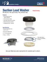
6. Permanently ground the motor using the internal, green
ground terminal located on the inside of the motor canopy
or access plate (Figure 1). Use the correct wire size and type
specified by National Electrical Code. Make sure the ground
wire is connected to an electrical service ground.
7. Bond the motor to the pool structure in accordance with the
National Electrical Code. Use a solid No. 8 AWG or larger copper
conductor. Run a wire from the brass external bonding clamp
(Figure 1) to the pool bonding structure.
8. Connect the pump permanently to a circuit. Make sure no
other lights or appliances are on the same circuit.
SUPPLY WIRE SIZES (AWG)
Size and Length by Horsepower
HP 115 Volts 230 Volts
50 Ft. 100 Ft. 150 Ft. 50 Ft. 100 Ft. 150 Ft.
1/3 14 14 12 14 14 14
1/2 14 12 10 14 14 14
3/4 12 12 10 14 14 14
112 10 8 14 14 14
1 1/2 10 10 8 14 14 12
210 8 8 14 12 12
3– – – 12 12 12
CHART 1
FIGURE 1
NOTE: If the pump is installed below the water level of the pool, close return and suction lines prior to opening
hair and lint pot on pump. Make sure to re-open valves prior to operating.
External Bonding Clamp Internal Grounding Screw
2

PUMP STRAINER BASKET
1. Turn off motor.
2. Relieve pressure in the system.
3. Turn the lid in a counter-clockwise direction until it stops.
4. Lift lid and remove basket.
5. Put the debris from the basket into the trash and rinse out the
basket. If the basket is cracked, it should be replaced.
6. Replace the basket and fill the pump pot and volute up to the
inlet port with water.
7. Clean the cover, O-ring and sealing surface of the pump pot.
Grease the O-ring with Teflon or silicone.
8. Reinstall the lid (Figure 2).
9. Make sure the lid O-ring is properly placed. Seat the lid then turn
clockwise until hand tight (DO NOT over tighten with tools)
(Figure 3).
10. Turn the power “ON” at the house circuit breaker. Reset the pool
time clock to the correct time.
11. Open the manual air relief valve on top of the filter.
12. Stand clear of the filter. Start the pump.
13. Bleed air from the filter until a steady stream of water comes out.
Close the manual air relief valve.
FIGURE 2
FIGURE 3
WARNING: DO NOT open the strainer pot if pump fails to prime or if pump has been operating without water in the
strainer pot. Pumps operated in these circumstances may experience a build up of vapor pressure and may contain
scalding hot water. Opening the pump may cause serious personal injury. In order to avoid the possibility of personal
injury, make sure the suction and discharge valves are open and strainer pot temperature is cool to touch, then with
extreme caution.
WARNING: THIS FILTER OPERATES UNDER HIGH PRESSURE. WHEN ANY PART OF THE CIRCULATION SYSTEM (e.g.
LOCK RING, PUMP, FILTER, VALVES, ETC) IS SERVICED, AIR CAN ENTER THE SYSTEM AND BECOME PRESSURIZED.
PRESSURIZED AIR CAN CAUSE THE LID TO BLOW OFF WHICH CAN RESULT IN SEVERE INJURY, DEATH, OR PROPERTY
DAMAGE. TO AVOID THIS POTENTIAL HAZARD, FOLLOW THESE INSTRUCTIONS.
This unit, sometimes referred to as the “Hair and Lint Pot”, is the unit in front of the volute. The lint pot must be installed using only teflon tape on
the threads. Do not use liquid chemical thread sealant. The basket inside the chamber must be kept clean of leaves and debris at all times. View
basket through the “See Through Lid” to inspect for leaves and debris. Regardless of the length of time between filter cleaning, it is most important
to visually inspect the hair and lint pot basket at least once a week. A dirty basket will reduce the efficiency of the filter and heater and also put an
abnormal stress on the pump motor which would result in a costly repair bill.
CAUTION: To prevent damage to the pump and filter and for proper operation of the system, clean pump strainer
and skimmer baskets regularly.
Lid
O-Ring
Basket
Pot
Lid
Volute
3

WINTERIZING CARE OF ELECTRIC MOTOR
If the air temperature drops below 35º F. the water in the pump
can freeze and cause damage. Freeze damage is not warrantable.
To prevent freeze damage follow the procedures listed below.
1. Shut off electrical power for the pump at the house circuit breaker.
2. Drain the water out of the pump case by removing the two drain
plugs from the case. Store the plugs in the pump basket.
3. Cover the motor to protect it from severe rain, snow, and ice.
4. Do not wrap the motor in plastic. It will cause condensation and rust
on the inside of the motor.
PROTECT FROM HEAT
1. Shade the motor from the sun.
2. Any enclosure must be well ventilated to prevent overheating.
3. Provide ample cross ventilation.
PROTECT AGAINST DIRT
1. Protect from any foreign matter or splashing water.
2. Do not store (or spill) pool chemicals near the motor.
3. Avoid sweeping or stirring up dust near the motor while it is
operating.
4. If a motor has been damaged by it voids the warranty.
PROTECT AGAINST MOISTURE
1. Protect from splashing pool water.
2. Protect from the weather.
3. Protect from lawn sprinklers.
4. If a motor has become wet – let it dry before operating. Do not allow
the pump to operate if it has been flooded.
5. If a motor has been damaged by water it voids the motor warranty.
NOTE: DO NOT wrap motor with plastic or other air tight materials. The motor may be covered during a storm,
for winter storage, etc., but NEVER when operating or expecting operation.
WARNING: RISK OF ELECTRICAL SHOCK OR ELECTROCUTION. This pool pump must be installed by a licensed or
certified electrician or a qualified pool serviceman in accordance with the National Electrical Code and all applicable
local codes and ordinances. Improper installation will create an electrical hazard which could result in death or damage
to property. Always disconnect power to the pool pump at the circuit breaker before servicing the pump. Failure to do
so could result in death or serious injury to serviceman, pool users or others due to electric shock.
WARNING: DO NOT open the strainer pot if pump fails to prime or if pump has been operating without water in the
strainer pot. Pumps operated in these circumstances may experience a build up of vapor pressure and may contain
scalding hot water. Opening the pump may cause serious personal injury. In order to avoid the possibility of personal
injury, make sure the suction and discharge valves are open and strainer pot temperature is cool to touch, then with
extreme caution.
4

PUMP DISASSEMBLY
PUMP REASSEMBLY / SEAL REPLACEMENT (FIGURE 4)
All moving parts are located in rear sub-assembly of this pump.
Tools required:
• ½ inch open end wrench
• 9/16 inch open end wrench
• Flat and Phillips head screwdrivers
To remove and repair the motor sub-assembly perform the
following procedures.
1. Turn off the pump circuit breaker at the main panel.
2. Drain the pump by removing the drain plugs.
3. Remove the 6 bolts that hold the main pump body (strainer pot/
volute) to the rear sub-assembly.
4. GENTLY pull the two pump halves apart, removing the rear sub-
assembly.
5. Remove the diffuser.
6. Hold the impeller securely in place and remove the impeller lock
screw by using a Phillips head screwdriver. The screw is a left-
handed thread and loosens in a clockwise direction.
7. Remove the shaft cap located at the back of the motor and hold the
shaft secure with a flat-head screwdriver (Century) or 7/16 inch
open-end wrench (Franklin) .
8. To unscrew the impeller from the shaft, twist the impeller counter
clockwise.
9. Remove the four bolts from the seal plate to the motor, using a 9/16
inch wrench.
10. Place the seal plate face down on a flat surface and tap out the
carbon/spring seal.
11. Clean the seal plate, seal housing, and motor shaft.
1. When installing the replacement ceramic/carbon seal, use silicone
sealant on the metal portion, before pressing into the seal plate.
2. Before installing the ceramic section of the seal into the impeller,
be sure the impeller is clean. Use a light density soap and water to
clean the seal. Press the seal into the impeller with your thumbs
and wipe off the ceramic and carbon faces with a clean cloth.
3. Remount the seal plate to the motor.
4. Screw the impeller onto the motor shaft.
5. Screw in the impeller lock screw (counter-clockwise to tighten).
6. Remount the diffuser onto the seal plate.
7. Grease the diffuser O-ring.
8. Assemble the motor sub-assembly to the strainer pot-pump body.
DO NOT tighten down any of the bolts until all 6 bolts are in place
and finger tight.
9. Fill the pump with water.
10. Reinstall the pump lid by turning clockwise until hand tight (DO
NOT over tighten with tools).
11. Prime the system; see Priming the Pump.
CAUTION: Be sure not to scratch or mar the polished seal faces. Seal will leak if faces are damaged.
CAUTION: The polished and lapped faces of the seal could be damaged if not handled with care.
Face Plate
Motor Shaft
Hex
Bolts
Gasket
Screw
Diuser
Assembly
O-Ring
Impeller
Pump Seal
FIGURE 4
5

22
21
20
27
18
17
16
15
14
12
11
910
8
6
30
5
4
3
1
2
7
29
26
13
28
FIGURE 3
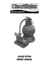
Part No. Qty Description
1 - 1 Motor
2 819-0035 3 Bolt .375-16 X .875 Long
3 672-1350 1 Neoprene Motor Support Strip
4 319-1500 1 Motor Support Base
5 819-0013 2 Screw Slot Hex Washer 1/4” X 1_1/4”
6 820-0017 6 3/8” Flat Washer Type B, Pool Pumps
7 319-1700 1 Handle
8 311-1450 1 Face Plate
9 806-1400 1 Gasket, Face Plate
10 319-3080 1 Pump Seal Set-Viton
11 711-4300 1 Washer, Impeller
12 819-4360 1 Screw Phil. Pan Head Left Hand 1/4-20 X 1”
13 310-7470 1 Diffuser Assy
14 819-0018 2 #4-40 Uncs Bolt Schs
15 805-0238 1 0-Ring-238
SMF PUMP REPLACEMENT PARTS
Part No. Qty Description
16 319-1420 1 Diffuser Plate
17 715-1201 2 3/8” Quarter Slot Plug (Sd Wet End)
18 805-0112 2 O-Ring, -014
20 319-1430 1 Basket Assy
21 805-0436 1 O-Ring, 6” Trap Lid
22 319-4100 1 Lid Assembly, 6” Trap
26 310-7500 1 SMF Max 3/4 HP Impeller Assembly
310-7510 1 SMF Max 1 HP Impeller Assembly
310-7520 1 SMF Max 1.5 HP Impeller Assembly
310-7530 1 SMF Max 2 HP Impeller Assembly
27 315-1400 1 Pump Housing - 2” X 2” Npt
28 820-0017-1 6 3/8” Washer, Split Lock
29 820-4280 6 Brass Insert, 3/8-16 Unc Housing
30 819-0016 6 3/8”-16 X 2” Lg Hex Head
6

RESTARTING INSTRUCTIONS & PRIMING THE PUMP
TROUBLESHOOTING
If the pump is installed below the water level of the pool, close
return and suction lines prior to opening hair and lint pot on
pump. Make sure to re-open valves prior to operating.
The pump strainer pot must be filled with water before the pump
is initially started. Follow these steps to prime the pump. For
2-speed pumps: Pump should run on high-speed for priming.
1. Remove the pump lid.
2. Fill the pump strainer pot with water.
3. Reassemble the pump lid onto the strainer pot. The pump is now
ready to prime.
4. Open the manual air relief valve on top of the filter, and stand clear
of the filter.
5. Turn on the switch or time clock.
6. When water comes out of the manual air relief valve, close the
valve. The system should now be free of air and circulating water to
and from the pool.
NOTE: Self-priming pump may take up to 3 ½ minutes to reach a
lift height of 10 feet.
CAUTION: DO NOT run the pump dry. If the pump is run dry, the mechanical seal will be damaged and the pump
will start leaking. If this occurs, the damaged seal must be replaced. ALWAYS maintain proper water level in
your pool. If the water level falls below the skimmer opening, the pump will draw air through the skimmer,
losing the prime and causing the pump to run dry, resulting in a damaged seal.
FAILURE OF PUMP
1. Pump will not prime, too much air. Remedy:
a. Check suction piping and valve glands on all suction gate valves.
b. Secure lid on pump strainer pot and make sure lid gasket is in place.
c. Check water level to make sure skimmer is not drawing air.
2. Pump will not prime, not enough water. Remedy:
a. Make sure suction lines, pump strainer, and pump volute are full of
water.
b. Make sure valve on suction line is working and open (some systems
do not have valves).
c. Check water level to make sure water is available through skimmer.
REDUCED FLOW AND/OR HEAD
1. Air pockets or leaks in suction line. Remedy:
a. See item 1a of this section above.
2. Clogged impeller. Remedy:
a. Turn off electrical power to the pump.
b. Remove the bolts holding the volute to the seal plate.
c. Slide the motor and seal plate away from the volute.
d. Remove the diffuser.
e. Clean debris from impeller. If debris cannot be removed, complete the
following steps:
(1) Remove left hand threaded bolt and gasket.
(2) Remove, clean and reinstall impeller.
(3) Reinstall left hand threaded bolt and gasket.
f. Reinstall the diffuser and diffuser O-ring.
g. Reinstall motor and seal plate into volute.
h. Tighten bolts securely.
3. Pump strainer clogged. Remedy:
a. Clean suction trap.
WARRANTY
For product registration visit: www.waterwayplastics.com.
For Warranty questions or claims please contact point of purchase.
810-0226.0618
©2018 Waterway Plastics
2200 East Sturgis Road, Oxnard CA 93030 • Phone 805.981.0262 • Fax 805.981.9403
www.waterwayplastics.com • [email protected]
Designed,
Engineered &
Manufactured
in the USA.
/