Page is loading ...

!
WARNING
High pressure can cause serious injury.
Follow the pressure-relief procedure on page 3 before
opening the lid or performing maintenance on the tank.
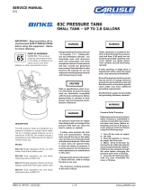
DESCRIPTION
Binks Hose/Gun Cleaner provides a means of cleaning
the inside of material hose, fluid passageways of
spray guns, and other paint equipment. It is
designed to mix solvents and compressed air to
pressure flush paint lines and passages quickly and
thoroughly, eliminating color contamination and
saving time. This results in clean and dry paint
passageways using less than 25% of cleaning
solvents required in wet flush systems.
Important: Read and follow all instructions and SAFETY PRECAUTIONS
before using this equipment. Retain for future reference.
Material Hose
Main Air
Line
Material
Hose
Hose/Gun
Cleaner
Fluid
Outlet
Regulate
to 110 psi
max.
Material
Tank
Main Air
Hose
Filter
Regulator
Assembly
Typical Installation
WETTED PARTS
Galvanized steel, aluminum, nickel plated brass,
PTFE, Santoprene®, Sarlink®, and polyethylene.
!
WARNING
Static electricity produced when using this Hose/Gun Cleaner can
cause serious injury.
To prevent sparks from static electricity, you must ground:
1. The Hose/Gun Cleaner
2. The gun or tool attached to the fluid hose
3. The equipment to be cleaned
To Ground equipment:
1. Use air hose containing static electricity grounding wire.
2. Attach one end of a ground wire to each item listed above.
3. Attach the other end of the wire to a water pipe, metal
electrical conduit, or any pipe or structural member known to
be grounded.
SPECIFICATIONS
Maximum Working
Pressure
110 psi
Capacity Up to 2.8 Gallons
Tank Shell SA-414 Steel, Galvanized (Zinc)
Tank Lid SA-414 Steel, Galvanized (Zinc)
Fluid Tube 3/8 in. Steel Pipe, Galvanized
Fluid Outlet 3/8 NPS(M) (Plated Brass)
Air Inlet 1/4 NPS(M)
Hose Cleaner Hub Aluminum
Plugs Steel, Zinc Plate
Clean equipment extremely efficiently with less solvent
183GZ-5200
2 GALLON HOSE/GUN CLEANER
77-2933-R2 (8/2018) 1 / 8 www.carlisleft.com
EN
SERVICE MANUAL

Binks reserves the right to modify equipment specification without prior notice.
LOCK OUT / TAG-OUT
Failure to de-energize, disconnect, lock out and tag-out all power
sources before performing equipment maintenance could cause
serious injury or death.
OPERATOR TRAINING
All personnel must be trained before operating finishing
equipment.
EQUIPMENT MISUSE HAZARD
Equipment misuse can cause the equipment to rupture,
malfunction, or start unexpectedly and result in serious injury.
PROJECTILE HAZARD
You may be injured by venting liquids or gases that are released
under pressure, or flying debris.
PINCH POINT HAZARD
Moving parts can crush and cut. Pinch points are basically any
areas where there are moving parts.
INSPECT THE EQUIPMENT DAILY
Inspect the equipment for worn or broken parts on a daily basis.
Do not operate the equipment if you are uncertain about its
condition.
In this part sheet, the words WARNING, CAUTION and NOTE are used to
emphasize important safety information as follows:
Hazards or unsafe practices which
could result in minor personal injury,
product or property damage.
!
CAUTION
Hazards or unsafe practices which
could result in severe personal
injury, death or substantial property
damage.
!
WARNING
Important installation, operation or
maintenance information.
NOTE
Read the following warnings before using this equipment.
READ THE MANUAL
Before operating finishing equipment, read and understand all
safety, operation and maintenance information provided in the
operation manual.
WEAR SAFETY GLASSES
Failure to wear safety glasses with side shields could result in
serious eye injury or blindness.
NEVER MODIFY THE EQUIPMENT
Do not modify the equipment unless the manufacturer provides
written approval.
IT IS THE RESPONSIBILITY OF THE EMPLOYER TO PROVIDE THIS INFORMATION TO THE OPERATOR OF THE EQUIPMENT.
FOR FURTHER SAFETY INFORMATION REGARDING THIS EQUIPMENT, SEE THE GENERAL EQUIPMENT SAFETY BOOKLET (77-5300).
KNOW WHERE AND HOW TO SHUT OFF THE EQUIPMENT
IN CASE OF AN EMERGENCY
PRESSURE RELIEF PROCEDURE
Always follow the pressure relief procedure in the equipment
instruction manual.
NOISE HAZARD
You may be injured by loud noise. Hearing protection may be
required when using this equipment.
STATIC CHARGE
Fluid may develop a static charge that must be dissipated through
proper grounding of the equipment, objects to be sprayed and all
other electrically conductive objects in the dispensing area. Improper
grounding or sparks can cause a hazardous condition and result in
fire, explosion or electric shock and other serious injury.
WEAR RESPIRATOR
Toxic fumes can cause serious injury or death if inhaled.
Wear a respirator as recommended by the fluid and solvent
manufacturer’s Safety Data Sheet.
TOXIC FLUID & FUMES
Hazardous fluid or toxic fumes can cause serious injury or death if
splashed in the eyes or on the skin, inhaled, injected or
swallowed. LEARN and KNOW the specific hazards or the fluids
you are using.
KEEP EQUIPMENT GUARDS IN PLACE
Do not operate the equipment if the safety devices have been
removed.
!
WARNING
AUTOMATIC EQUIPMENT
Automatic equipment may start suddenly without warning.
FIRE AND EXPLOSION HAZARD
Improper equipment grounding, poor ventilation, open flame or
sparks can cause a hazardous condition and result in fire or
explosion and serious injury.
MEDICAL ALERT
Any injury caused by high pressure liquid can be serious. If you
are injured or even suspect an injury:
• Go to an emergency room immediately.
• Tell the doctor you suspect an injection injury.
• Show the doctor this medical information or the medical alert
card provided with your airless spray equipment.
• Tell the doctor what kind of fluid you were spraying or
dispensing.
GET IMMEDIATE MEDICAL ATTENTION
To prevent contact with the fluid, please note the following:
• Never point the gun/valve at anyone or any part of the body.
• Never put hand or fingers over the spray tip.
• Never attempt to stop or deflect fluid leaks with your hand,
body, glove or rag.
• Always have the tip guard on the spray gun before spraying.
• Always ensure that the gun trigger safety operates before
spraying.
EN
77-2933-R2 (8/2018)2 / 8www.carlisleft.com

HAZARD CAUSE SAFEGUARDS
Fire
Solvents and coatings can be highly
ammable or combustible, especially
when sprayed.
1. Adequate exhaust must be provided to keep the air free
of accumulations of ammable vapors.
2. Smoking must never be allowed in the spray area.
3. Fire extinguishing equipment must be present in the
spray area.
Fire – Pressure tank
Vapors from ammable liquids can
catch re or explode.
Keep tank at least 10 feet away from sources of ignition.
Ignition sources include hot objects, mechanical sparks, and
arcing (non -explosion proof) electrical equipment.
Explosion Hazard –
Pressure Tank –
Static Electricity
Static electricity is created by the
ow of uid through the pressure
tank and hose. If all parts are not
properly grounded, sparking may
occur. Sparks can ignite vapors from
solvents and the uid being sprayed.
1. Ground the pressure tank by connecting one end of 12
gauge (minimum) ground wire to the pressure tank and
the other end to a true earth ground. Local codes may
have additional grounding requirements.
2. See illustration on page 4 for grounding and grounding
hardware required.
Explosion Hazard –
Pressure Tank –
Rupture
Making changes to a pressure tank
will weaken it.
1. Never drill into, weld, or modify the tank in any way.
2. Do not adjust, remove, or tamper with the safety valve.
If replacement is necessary, use the same type and rating
of valve.
Explosion Hazard –
Galvanized Tanks –
Material Compatibility
Halogenated hydrocarbon solvents
– for example 1-1-1 Trichloroethane
and methylene chloride – can
chemically react with aluminum
parts and components and cause an
explosion hazard. These solvents
will also corrode the galvanized tank
coating.
1. Read the label or data sheet for the material. Do not
use materials containing these solvents with galvanized
pressure tanks. Stainless steel tank models may be used
with halogenated solvents.
2. Refer to specications chart to ensure that uids are
chemically compatible with the tank wetted parts.
Before placing uids or solvents in tank, always read
accompanying manufacturer’s literature.
General Safety
Improper operation or maintenance
may create a hazard.
Operators should be given adequate training in the safe
use and maintenance of the equipment (in accordance with
the requirements of NFPA-33, Chapter 15 in U.S.) Users
must comply with all local and national codes governing
ventilation, re precautions, operation, maintenance, and
housekeeping (in the U.S., these are OSHA sections 1910.94
and 1910.107, and NFPA-33.
The following hazards may occur during the normal use of this equipment. Please read the following chart.
!
WARNING
High pressure can cause
serious injury.
Pressure is maintained in a
pressure tank after the
system has been shut
down.
Always follow this
procedure to relieve
pressure from the tank.
1. Turn off the main air supply to the tank.
2. Close the air inlet valve located on the tank air manifold.
3. Bleed off air in the tank by turning the air relief valve (5) thumb screw counterclockwise. Wait until all the
air has escaped through the valve before removing the pressure tank cover or fill port cap.
4. Leave the air relief valve open until you have reinstalled the tank cover or fill port cap.
PRESSURE RELIEF PROCEDURE
To reduce the risk of injury, follow the pressure relief procedure below
• Before checking or servicing any
part of the spray system
• Before attempting removal of fill
port cap or tank cover
• Whenever the tank is left
unattended
EN
77-2933-R2 (8/2018) 3 / 8 www.carlisleft.com

BACK FLUSHING EXCESS
MATERIAL
When spraying is complete, back flush
remaining material in spray gun and hose as
follows:
1. Turn off air to material tank and bleed air
out of the material tank.
2. Loosen clamps on tank lid. Tip lid so
material will run out of fluid tube into
material tank.
3. Loosen air cap on gun 2 to 3 turns and
hold rag over cap. Pull trigger and force
material from gun and hose back into
tank.
TO CLEAN HOSE AND GUN
PASSAGES:
1. Fill Hose/Gun Cleaner with suitable
cleaning solvent. Note: This model cannot
be used with halogenated hydrocarbon
solvents. Close lid on cleaner.
2. Connect air hose to ¼ NPS(M) ball valve
(4). Close ball valve. Regulate air pressure
(must be remotely regulated) to a
maximum of 110 PSI.
3. Disconnect material hose from material
supply tank and connect to 3/8 NPS(M)
ball valve (5).
4. Open both ball valves.
5. Turn metering valve on top of the Hose/
Gun Cleaner to adjust the solvent-to-air
ratio. Turn counterclockwise to increase
solvent and clockwise to decrease solvent.
Fully clockwise shuts off solvent
completely. To begin, open
counterclockwise 2 turns for sufficient
solvent for cleaning.
6. Trigger gun into a properly grounded
container. Continue spraying until solvent
is clear with no traces of paint.
7. Turn metering valve full clockwise,
shutting off solvent flow, while allowing air
to continue to flow. Continue until all
solvent is removed.
8. Turn off air at source. Trigger gun to
remove residual air pressure. Close both
ball valves.
PREVENTIVE MAINTENANCE
Check Lid Gasket (11) and Needle Valve
Gasket (2) for signs of wear or damage.
Replace as needed.
Lift ring on safety valve (6) once a week to
unseat it and make sure that it is working
properly. Safety valve should be kept clean
and free of dirt ad paint at all times.
ACCESSORIES
Air Supply Hose
71-20000 Air Hose – with static ground wire
braid, 5/16” ID. Also need two re-useable
72-1317 connectors.
Or
71-2100 Air Hose – with static ground wire
braid, 3/8” ID. Also need two re-useable
72-1325 connectors.
Or
Fluid Delivery Hose
71-282 Nylon lined fluid hose – 3/8” ID. Also
need two re-useable 72-1328 connectors.
GROUNDING DIAGRAM
Purchase hardware locally
5/16–18 x 3/4 Long
Hex Head Bolt
(1 Required)
2X
5/16–18 Hex Head
Nut (2 Required)
Sufcient Length
12 Gauge Wire
(Not Shown)
5/16 Lock Washer
(1 Required)
Tank Skirt (Ref)
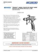
ITEM
NO. PART NO. DESCRIPTION QTY.
1 HD-409 NEEDLE VALVE ASSEMBLY 1
2 HD-39-K2 NEEDLE VALVE GASKET (KIT 0F 2) 1
3 HD-430 HD SUB ASSEMBLY 1
4 VA-542 BALL VALVE (1/4 NPS) 1
5 VA-540 BALL VALVE (3/8 NPS) 1
6 TIA-5110 SAFETY VALVE ASSEMBLY 1
7 SSG-8184-K2 O-RING (KIT OF 2) 1
8 • ----- PLUG (1/2-14 NPT) 1
9 • ----- PLUG (3/8-18 NPT) 1
10 QMG-400 TANK LID 1
11 QMS-80-1 TANK GASKET 1
12 QMS-9-1 FLUID TUBE 1
13 PT-78-K10 TANK LINER (KIT OF 10) 1
14 KK-5013 CLAMP, PIN, & SCREW KIT 4
15 QMG-502-1 TANK & LUG ASSEMBLY 1
• Purchase locally
1
2
4
3
78
10
11
13
12
14
15
5
6
9
EN
77-2933-R2 (8/2018)4 / 8www.carlisleft.com

NOTES
EN
77-2933-R2 (8/2018) 5 / 8 www.carlisleft.com

NOTES
EN
77-2933-R2 (8/2018)6 / 8www.carlisleft.com

NOTES
EN
77-2933-R2 (8/2018) 7 / 8 www.carlisleft.com

EN
77-2933-R2 (8/2018)8 / 8www.carlisleft.com
WARRANTY POLICY
This product is covered by Carlisle Fluid Technologies’ materials and workmanship limited warranty.
The use of any parts or accessories, from a source other than Carlisle Fluid Technologies,
will void all warranties. Failure to reasonably follow any maintenance guidance provided
may invalidate any warranty.
For specic warranty information please contact Carlisle Fluid Technologies.
For technical assistance or to locate an authorized distributor,
contact one of our international sales and customer support locations.
Region Industrial/Automotive Automotive Renishing
Americas Tel: 1-800-992-4657 Tel: 1-800-445-3988
Fax: 1-888-246-5732 Fax: 1-800-445-6643
Europe, Africa,
Middle East, India
Tel: +44 (0)1202 571 111
Fax: +44 (0)1202 573 488
China Tel: +8621-3373 0108
Fax: +8621-3373 0308
Japan Tel: +81 45 785 6421
Fax: +81 45 785 6517
Australia Tel: +61 (0) 2 8525 7555
Fax: +61 (0) 2 8525 7575
Carlisle Fluid Technologies is a global leader in innovative nishing technologies.
Carlisle Fluid Technologies reserves the right to modify equipment specications without prior notice.
DeVilbiss®, Ransburg®, ms®, BGK®, and Binks®
are registered trademarks of Carlisle Fluid Technologies, Inc.
©2018 Carlisle Fluid Technologies, Inc.
All rights reserved.
For the latest information about our products, visit www.carlisleft.com
/