Pepperl+Fuchs VAS/M-2A8L-KE4-6SE-EV User manual

Type
User manual

The Pepperl+Fuchs VAS/M-2A8L-KE4-6SE-EV Safety Basic Monitor is a versatile and reliable device designed to enhance the safety of your industrial machinery and processes. With its advanced features and capabilities, it offers a comprehensive solution for monitoring and controlling safety-critical functions. Here are some key aspects of this device:

  • Safety Certification: The VAS/M-2A8L-KE4-6SE-EV meets stringent safety standards, including EN ISO 13849-1 (Performance Level e, Safety Integrity Level 3) and IEC 61508/EN 62061 (SIL 3). This certification ensures the highest level of safety and reliability in critical applications.
Hinweise zur Benutzung der Anschluss- und Betriebsanleitung
Diese Anschluss- und Betriebsanleitung enthält Informationen über den bestim-
mungsgemäßen und effektiven Einsatz des Gerätes.
Detaillierte Informationen siehe Handbücher „Safety Basis Monitor“ und „ASIMON
Konfigurationssoftware“.
Sicherheits- und Warnhinweise sind mit dem Symbol gekennzeichnet.
Pepperl+Fuchs GmbH haftet nicht für Schäden, die durch unsachgemäße Benut-
zung entstehen. Zur sachgerechten Verwendung gehört auch die Kenntnis dieser An-
leitung.
© Nachdruck und Vervielfältigung, auch auszugsweise, nur mit ausdrücklicher
Genehmigung durch:
Pepperl+Fuchs GmbH
Lilienthalstraße 200 * 68301 Mannheim
Telefon (06 21) 7 76-11 11 * Telefax (06 21) 7 76 27-11 11
Internet http://www.pepperl-fuchs.com
Diese Betriebsanleitung ist Bestandteil des Lieferumfangs.
Technische Daten
Derating bei AS-i Entkopplung aus AUX
Stillstands-/Drehzahlwächter an lokalen Eingängen
Sicherheitstechnische Kenndaten
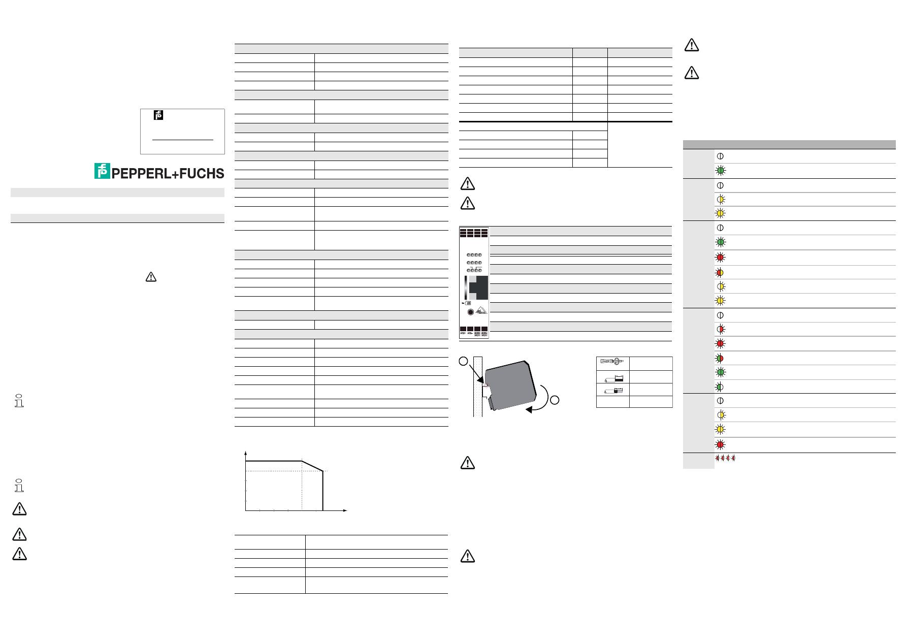
Anschlüsse und Bedienelemente
Montage
Die Montage des Gerätes erfolgt auf 35 mm Normschienen nach EN 60715.
Setzen Sie das Gerät zur Montage an der Oberkante der Normschiene an und
schnappen Sie es dann an der Unterkante ein.
Wartung
Die einwandfreie Funktion des Gerätes innerhalb des absichernden Systems, d. h.
das sichere Abschalten bei Auslösung eines zugeordneten sicherheitsgerichteten
Sensors oder Schalters, ist vom Sicherheitsbeauftragten mindestens jährlich zu kon-
trollieren.
LED Statusanzeige
Originalbetriebsanleitung VAS/M-2A8L-KE4-6SE-EV
Safety Basis Monitor
erweiterter Funktionsumfang, Safe Link, Modbus TCP-Diagnosefähigkeit
Bestimmungsgemäßer Gebrauch
Der Safety Basis Monitor ist als abschaltende Schutzvorrichtung für das
Absichern von Gefahrenbereichen an kraftbetriebenen Arbeitsmitteln
entwickelt worden. Dabei wird das Arbeitsstromprinzip angewendet. Da-
mit sind diese Ausgänge dann einsetzbar, wenn der sichere Zustand
durch abschalten der Energie erreicht werden kann.
Das Gerät ist für den Einsatz von Sicherheitsanwendungen bis
Kategorie 4 / PL e / SIL 3 zugelassen.
Das Gerät darf nur in den Grenzen seiner technischen Daten betrieben
werden. Es darf nur mit den vorgeschriebenen Strom- und Spannungs-
werten betrieben werden.
Fehlerzustände von den in der sicheren Konfiguration verwendeten si-
cheren Remoteausgängen können durch Stoppen und Starten des Mo-
nitors behoben werden.
Zum Anschluss und zur Inbetriebnahme des Gerätes gehört die Kennt-
nis der Betriebsanleitung sowie des Benutzerhandbuchs der ASIMON
Konfigurations- und Diagnosesoftware.
Der Besteller hat die Rückverfolgbarkeit der Geräte über die Serien-
nummer sicherzustellen.
Personenschutzfunktion
Das Gerät erfüllt eine Personenschutzfunktion. Unsachgemäßer Einbau
beeinträchtigt die Funktion! Der Hersteller der Maschine/Anlage, an der
das sicherheitsgerichtete System eingesetzt wird, ist verantwortlich für
die korrekte und sichere Gesamtfunktion aller einzelnen Sicherheits-
komponenten! Je nach Auswahl der verwendeten Sicherheitsbauteile
kann die Einstufung des gesamten Sicherheitssystems auch in eine
niedrigere Sicherheitskategorie erfolgen!
Ausgabedatum: 14.8.15
Technische Änderungen vorbehalten
Safety Basic Monitor with Ethernet
diagnostic and Modbus TCP
diagnostic capability
PEPPERL+FUCHS
Lilienthalstraße 200
D-68307 Mannheim
Made in Germany
VAS/M-2A8L-KE4-6SE-EV
Allgemein
AS-i / AUX / Peripherieanschluss COMBICON-Stecker
Länge Anschlusskabel unbegrenzt (Schleifenwiderstand 150 )
AS-i Master integriert
Netzteilentkopplung integriert
Schnittstelle
Diagnose- und
Konfigurationsschnittstelle Ethernet + Modbus/TCP
Kartensteckplatz Chipkarte zur Speicherung von Konfigurationsdaten
AS-i
Spannung 30 VDC
Max. Stromverbrauch 200 mA
AUX
Spannung 24 VDC
Max. Stromverbrauch 4 A
Eingang
Eingänge Safety, SIL 3, Kat. 4 3 x 2-kanalig; Eingang 3 optional für Drehzahlwächter
Eingänge digital, EDM bis zu 6 Standard-Eingänge bzw. Meldeausgänge
Schaltstrom statisch 4 mA bei 24 V;
dynamisch 15 mA bei 24 V (T = 100 µs)
Versorgungsspannung aus AUX
Anschlussbedingungen
zwischen sicheren
Eingangsklemmen max. Widerstand 150
Ausgang
Anzahl 2 Halbleiter-Ausgänge (Ausgangskreise 1 und 2)
max. Kontaktbelastbarkeit 700 mADC-13 bei 24 V (Derating)
Versorgungsspannung aus AUX
Max. Ausgangsstrom 10 mA je Meldeausgang
Testpuls wenn Ausgang eingeschaltet ist: minimaler Abstand zwi-
schen 2 Testpulsen: 250 ms, Impulslänge bis 1 ms
Anzeige
LED Anzeige siehe Tabelle “LED Statusanzeige”
Umwelt
Betriebshöhe max. 2000 m
Umgebungstemperatur 0 °C … +55 °C
Lagertemperatur -25 °C … +85 °C
Gehäuse Kunststoff, Klemmschienengehäuse
Schutzart (EN 60529) IP20
Zulässige Schock- und
Schwingbeanspruchung gemäß EN 61131-2
Isolationsspannung 500 V
Gewicht 160 g
Maße (B / H / T in mm) 22,5 / 99 / 114
Anzahl Achsen 2 x 2-kanalig, SIL2, PLd oder
2 x 1-kanalig, SIL1, PLc (nur Drehzahlwächter)
Frequenzbereich Nutzfrequenz bis 4 kHz; max. zulässig 5 kHz
Auflösung 0,1 Hz
Puls- und Pausenzeit 80 µs
max. Fehlererkennungszeit
I
AS-i
, max [mA]
400
500
40 55
T
amb
[°C]
31
Frequenz
---------------------------- 4 0 m s+
Kenndaten Wert Norm
Sicherheitskategorie 4 EN ISO 13849-1
Performance Level (PL) e EN ISO 13849-1
Safety Integrity Level (SIL) 3 IEC 61508, EN 62061
Gebrauchsdauer (TM) [Jahr] 20 EN ISO 13849-1
Maximale Einschaltdauer [Monat] 12 IEC 61508
PFD 9,58 x 10⁻⁷ EN 62061
PFHD [1/h] 5,08 x 10⁻⁹ IEC 61508, EN 62061
Max. Reaktionszeit [ms]
IEC 61508
AS-i Eingangsslave lokaler Ausgang 40
lokaler Eingang lokaler Ausgang 20
lokaler Eingang AS-i Codefolge 26
AS-i Eingangsslave AS-i Codefolge 45
Wenn "Erhöhte Verfügbarkeit" eingestellt wird, verlängert sich die max.
Reaktionszeit (siehe Handbuch "ASIMON Konfigurationssoftware").
Die AS-i bzw. die 24 V-Versorgung muss aus einem PELV-Netzteil er-
folgen!
Ethernet Diagnoseschnittstelle
SET Teach/Service-Taster
Chip Card Chipkarte
1.14ext.out Anschluss Sicherer Halbleiter-Ausgang 1
2.14ext.out Anschluss Sicherer Halbleiter-Ausgang 2
0V
ext.out Masseanschluss für Halbleiter-Ausgang
ASI+, ASI– Anschluss an AS-i Bus
AUX+ext.in, AUX-ext.inAnschluss an ext. 24 VDC PELV
S22, S21, S12, S11 Sichere Eingangsklemmen Eingang 1
S42, S41, S32, S31 Sichere Eingangsklemmen Eingang 2
S62, S61, S52, S51 Sichere Eingangsklemmen Eingang 3
Fachgerecht installieren
Die elektrische Installation ist von eingewiesenem Fachpersonal durch-
zuführen. Bei der Installation ist darauf zu achten, dass Versorgungs-
und Signalleitungen und auch die AS-i Busleitung getrennt von Kraft-
stromleitungen verlegt sind. Im Schaltschrank ist darauf zu achten, dass
bei Schützen eine entsprechende Funkenlöschung verwendet wird. Bei
Antriebsmotoren und -bremsen ist auf die Installationshinweise in den
entsprechenden Bedienungsanleitungen zu achten. Bitte beachten Sie,
dass die maximale Leitungslänge für die AS-i Busleitung 100 m beträgt.
Darüber hinausgehende Leitungslängen erfordern den Einsatz geeigne-
ter Leitungsverlängerungen.
Bei der Verlegung der Leitungen ist sicherzustellen, dass keine
Spannungsverschleppung entstehen kann.
Montieren Sie das Sicherheitsschaltgerät in einem Schaltschrank mit ei-
ner Schutzart von mindestens IP54!
ETHERNET
CHIP CARD
O 2
S 61 S 52 S 51
S 41 S 32 S 31
S 21 S 12 S 11
1.14
ext.
out
0
V
1
ext.
out
2.14
ext.
out
0
V
2
ext.
out
S 62
S 42
S 22
SM
AS-i M O 1
S 5S 6
S 1 S 2S 3 S 4
SET
NET
0,6 Nm (5 Ibf
. in)
0,6 x 3,5 mm
7
7
AWG 24 ... 12
0,2 ... 2,5 mm2
0,2 ... 2,5 mm2
2
1
Dazu ist jeder sicherheitsgerichtete Eingang (lokal oder über einen
SaW-Eingangsslave angeschlossen) mindestens einmal pro Jahr zu
schalten und das Schaltverhalten durch Beobachtung der Ausgangs-
kreise des Gerätes zu kontrollieren.
Abhängig vom für die Gesamtversagenswahrscheinlichkeit gewählten
PFD-Wert ist die maximale Einschaltdauer und die Gesamtbetriebsdau-
er zu beachten.
Bei Erreichen der maximalen Einschaltdauer (s. sicherheitstechnische
Kenndaten) ist die ordnungsgemäße Funktion des Sicherheitssystems
durch Anforderung der Abschaltfunktion zu überprüfen.
Bei Erreichen der maximalen Gebrauchsdauer (TM) ist das Gerät vom
Hersteller auf seine ordnungsgemäße Funktion im Herstellerwerk zu
überprüfen.
LEDs Status Beschreibung
NET
(grün)
Modbus inaktiv
Modbus aktiv
S1 … Sn
(gelb)
Kontakt (S1 … Sn) offen
1 Hz Querschluss
Kontakt (S1 … Sn) geschlossen
SM1
1. ’Gelb’ hat Priorität vor ’Rot’ und ’Grün’ und wird bevorzugt angezeigt.
AS-i Spannung nicht OK
(grün) Schutzbetrieb aktiv
(rot) Konfigurationsbetrieb aktiv
(rot, gelb) 2 Hz Mindestens 1 Device im Zustand ’rot blinkend’ oder ’gelb blinkend’
(gelb)
1 Hz Service-Taster, Status ’Anlernfehler’
Service-Taster, Status ’Bereit’
AS-i M2
2. Liegen ’Config-Error’ und ’Peripheriefehler’ gleichzeitig vor, wird nur ’Config-Error’ angezeigt.
Offline, Monitor-Modus
(rot) 1 Hz Peripheriefehler ohne Config-Error
Config-Error, Autoadressierung nicht möglich
(rot, grün) 2 Hz Config-Error, Autoadressierung möglich
(grün)
Master: geschützter Modus, kein Fehler
1 Hz Master: Projektierungsmodus, kein Fehler
O1, O23
3. ’Rot’ hat Priorität vor ’Gelb’
Ausgang (O1, O2) aus
(gelb)
8 Hz behebbarer Fehlerzustand
Ausgang (O1, O2) an
(rot) AUX Spannung fehlt
SM, AS-i M,
O1, O2 1Hz Konkurierende Master aktiv
Notes on using these connection and operating instructions
These connection and operating instructions contain information regarding the proper
and effective use of the device.
See the manuals "Safety Basic Monitor" and "ASIMON configuration software" for de-
tailed information.
Safety precautions and warnings are designated by the symbol.
Pepperl+Fuchs GmbH is not liable for damage resulting from improper use of its
equipment. Familiarity with these instructions constitutes part of the knowledge re-
quired for proper use.
© Reprint and reproduction, in whole or in part, only with the explicit permission of:
Pepperl+Fuchs GmbH
Lilienthalstraße 200 * 68301 Mannheim
Telefon (06 21) 7 76-11 11 * Telefax (06 21) 7 76 27-11 11
Internet http://www.pepperl-fuchs.com
This operating instruction is a part of the scope of delivery.
Technical data
Derating at AS-i decoupling out of AUX
Standstill-/Speed Monitor on local inputs
Safety characteristics
Connections and controls
Assembly
The device is mounted on 35 mm standard rails in accordance with EN 60715.
For assembling, position the device on the upper edge of the standard rail and then
snap it onto the bottom edge.
Maintenance
The proper function of the device within the system to be secured, i.e. the safe shut-
down following the triggering of an assigned safety related sensor or switch, is to be
checked at least once a year by the safety officer.
LED status display
Translation
of the original operating instructions VAS/M-2A8L-KE4-6SE-EV
Safety Basic Monitor
extended features, Safe Link, Modbus TCP diagnostic
Specified normal operation
The Safety Basic Monitor has been designed as a disconnecting protec-
tive device for safeguarding danger zones on power-driven work equip-
ment by applying the power to lock principle. Thereby these outputs are
only usable, if the safe state can be achieved by switching off the power.
The device is approved for safety applications up to Category 4 / PL e /
SIL 3.
The device may only be operated within the limits of its technical speci-
fications. It may only be operated with the specifiedcurrent and voltage
values.
Error states of the remote outputs used in the safe configuration can be
eliminated by starting and stopping the monitor.
For connecting and commissioning the device, comprehension of the
operating instructions as well as the operating instructions of ASIMON
configuration and diagnostic software is necessary.
The orderer has to guarantee the traceability of the devices via the serial
number.
Person protection function
The device fulfills a person protection function. Improper installation im-
pairs the function! The manufacturer of the machine/plant in which the
safety related system is used is responsible for the correct and safe total
function of every individual safety component! Depending on the choice
of safety devices used, the safety system as a whole may also be as-
signed to a lower safety category!
Issue date: 2015-8-14
Subject to change without prior notice
Safety Basic Monitor with Ethernet
diagnostic and Modbus TCP
diagnostic capability
PEPPERL+FUCHS
Lilienthalstraße 200
D-68307 Mannheim
Made in Germany
VAS/M-2A8L-KE4-6SE-EV
General
AS-i / AUX / Peripheral conneti-
on COMBICON clamps
Length of connector cable unlimited (loop resistance 150 )
AS-i master integrated
Decoupling of power supply integrated
Interface
Diagnostic and configuration
interface Ethernet + Modbus/TCP
Card slot chip card for storage of configuration data
AS-i
Voltage 30 VDC
Max. current consumption 200 mA
AUX
Voltage 24 VDC
Max. current consumption 4 A
Input
Inputs safety, SIL 3, cat. 4 3 x 2 channels; input 3 optional for speed monitor
Inputs digital, EDM up to 6 standard inputs or signal outputs
Switching current static 4 mA at 24 V,
dynamic 15 mA at 24 V (T = 100 µs)
Power supply out of AUX
Network connection between the
safe input terminals max. resistance 150
Output
Number 2 semiconductor outputs (output circuits 1 and 2)
Max. contact load 700 mADC-13 at 24 V (derating)
Power supply out of AUX
Max. output current 10 mA per signal output
Test pulse if output is on: minimum interval between 2 test pulses:
250 ms, maximum pulse width 1 ms
Display
LED display see table “LED status display”
Environment
Operating altitude max. 2000 m
Ambient operating temperature 0 °C … +55 °C
Storage temperature -25 °C … +85 °C
Housing plastic, for DIN rail mounting
Protection category (EN 60529) IP20
Tolerable loading referring to im-
pacts and vibrations acc. EN 61131-2
Voltage of insulation 500 V
Weight 160 g
Dimensions (W / H / D in mm) 22,5 / 99 / 114
Number of axes 2 x 2-channel, SIL2, PLd or
2 x 1-channel, SIL1, PLc (speed monitor only)
Frequency range fundamental frequency up to 4 kHz,
max. permissible 5 kHz
Resolution 0,1Hz
Pulse- and pulse off time 80µs
Max. fault-detection time
I
AS-i
, max [mA]
400
500
40 55
T
amb
[°C]
31
Frequency
--------------------------------40ms+
Characteristics Value Standard
Safety category 4 EN ISO 13849-1
Performance Level (PL) e EN ISO 13849-1
Safety Integrity Level (SIL) 3 IEC 61508, EN 62061
Service life (TM) [year] 20 EN ISO 13849-1
Maximal power-on time (month) 12 IEC 61508
PFD 9,58 x 10⁻⁷ EN 62061
PFHD [1/h] 5,08 x 10⁻⁹ IEC 61508, EN 62061
Max. reaction time [ms]
IEC 61508
AS-i input slave local output 40
local input local output 20
local input AS-i code sequence 26
AS-i input slave AS-i code sequence 45
If the option „augmented reliability“ is selected the response time will ex-
tend (see manual „ASIMON configuration software“).
The AS-i and/or the 24 V must be supplied by a PELV power supply.
Ethernet diagnostic interface
SET teach/service button
Chip Card chip card
1.14ext.out connection safety semiconductor output 1
2.14ext.out connection safety semiconductor output 2
0V
ext.out ground for semiconductor outputs
ASI+, ASI– connection to the AS-i bus
AUX+ext.in, AUX-ext.inconnection for ext. 24 VDC PELV
S22, S21, S12, S11 safety input terminal input 1
S42, S41, S32, S31 safety input terminal input 2
S62, S61, S52, S51 safety input terminal input 3
Have installation done professionally
Electrical installation is to be performed by a trained expert. During in-
stallation, care must be taken that supply and signal cables and also the
AS-i bus cable are laid separately from high-voltage cables. In the
switch cabinet, it must be ensured that appropriate spark quenching
equipment is used with contactors. Where drive motors and brakes are
used, attention must be paid to the installation instructions in the corre-
sponding operating instructions. Please note that the maximum cable
length of the AS-i bus cable is 100 m. Cables above that length require
the use of a suitable circuit extension.
When installing the cables, make sure that no parasitic voltages can
arise.
Install the safety relay in a control cabinet with a minimum protection
type of IP54!
ETHERNET
CHIP CARD
O 2
S 61 S 52 S 51
S 41 S 32 S 31
S 21 S 12 S 11
1.14
ext.
out
0
V
1
ext.
out
2.14
ext.
out
0
V
2
ext.
out
S 62
S 42
S 22
SM
AS-i M O 1
S 5S 6
S 1 S 2S 3 S 4
SET
NET
0,6 Nm (5 Ibf
. in)
0,6 x 3,5 mm
7
7
AWG 24 ... 12
0,2 ... 2,5 mm2
0,2 ... 2,5 mm2
2
1
For this purpose, every safety related input (connected locally or over a
safety related SaW slave) must be activated at least once per year and
the switching behavior must be inspected by monitoring the output cir-
cuits of the device.
The maximum power-on time and total operating time depends on the
PFD value selected for the overall failure probability.
When the maximum power-on time has been reached (see safety char-
acteristics), the safety system must be checked to ensure that it is func-
tioning correctly by prompting the shutdown function.
When the maximum service life (TM) has been reached, the device must
be checked at the manufacturer's factory to ensure that it is functioning
correctly.
LEDs State Description
NET
(green)
Modbus inactive
Modbus active
S1 … Sn
(yellow)
contact (S1 … Sn) open
1 Hz cross connection
contact (S1 … Sn) closed
SM1
1. ’yellow’ has higher priority than ’red’ and ’green’ and will displayed preferentially.
AS-i voltage not OK
(green) ’protective mode’ active
(red) ’configuration mode’ active
(red, yellow) 2 Hz at least 1 device in state ’red flashing’ or ’yellow flashing’
(yellow)
1 Hz service button, state: ’teach error’
service button, state: ’ready’
AS-i M2
2. If ’config-error’ and ’peripheral fault’ occur simultaneously, only ’config-error’ is displayed.
off-line, monitor mode
(red) 1 Hz peripheral fault, without ’Config-Error’
’Config-Error’, auto addressing not possible
(red, green) 2 Hz ’Config-Error’, auto addressing possible
(green)
Master: ’protective mode’ , no error
1 Hz Master: ’configuration mode’, no error
O1, O23
3. ’red’ has higher priority than ’yellow’.
output (O1, O2) off
(yellow)
8 Hz correctable error state
output (O1, O2) on
(red) no auxiliary voltage
SM, AS-i M,
O1, O2 1Hz competing master active
  • Page 1 1
  • Page 2 2

Pepperl+Fuchs VAS/M-2A8L-KE4-6SE-EV User manual

Type
User manual

The Pepperl+Fuchs VAS/M-2A8L-KE4-6SE-EV Safety Basic Monitor is a versatile and reliable device designed to enhance the safety of your industrial machinery and processes. With its advanced features and capabilities, it offers a comprehensive solution for monitoring and controlling safety-critical functions. Here are some key aspects of this device:

  • Safety Certification: The VAS/M-2A8L-KE4-6SE-EV meets stringent safety standards, including EN ISO 13849-1 (Performance Level e, Safety Integrity Level 3) and IEC 61508/EN 62061 (SIL 3). This certification ensures the highest level of safety and reliability in critical applications.

Ask a question and I''ll find the answer in the document

Finding information in a document is now easier with AI