Page is loading ...

PU-2H8HBTE-AD
2 x 8 HDBaseT™ Switch with Audio Dembedding
OPERATION MANUAL


3
DISCLAIMERS
The information in this manual has been carefully checked and is
believed to be accurate. CYP (UK) Ltd assumes no responsibility for any
infringements of patents or other rights of third parties which may result
from its use.
CYP (UK) Ltd assumes no responsibility for any inaccuracies that may be
contained in this document. CYP (UK) Ltd also makes no commitment to
update or to keep current the information contained in this document.
CYP (UK) Ltd reserves the right to make improvements to this document
and/or product at any time and without notice.
COPYRIGHT NOTICE
No part of this document may be reproduced, transmitted, transcribed,
stored in a retrieval system, or any of its part translated into any language
or computer le, in any form or by any means—electronic, mechanical,
magnetic, optical, chemical, manual, or otherwise—without express
written permission and consent from CYP (UK) Ltd.
© Copyright 2011 by CYP (UK) Ltd.
All Rights Reserved.
Version 1.1 August 2011
TRADEMARK ACKNOWLEDGMENTS
All products or service names mentioned in this document may be
trademarks of the companies with which they are associated.

4
SAFETY PRECAUTIONS
Please read all instructions before attempting to unpack, install or operate
this equipment and before connecting the power supply.
Please keep the following in mind as you unpack and install this
equipment:
• Always follow basic safety precautions to reduce the risk of re,
electrical shock and injury to persons.
• To prevent re or shock hazard, do not expose the unit to rain,
moisture or install this product near water.
• Never spill liquid of any kind on or into this product.
• Never push an object of any kind into this product through any
openings or empty slots in the unit, as you may damage parts inside
the unit.
• Do not attach the power supply cabling to building surfaces.
• Use only the supplied power supply unit (PSU). Do not use the PSU if
it is damaged.
• Do not allow anything to rest on the power cabling or allow any
weight to be placed upon it or any person walk on it.
• To protect the unit from overheating, do not block any vents or
openings in the unit housing that provide ventilation and allow for
sucient space for air to circulate around the unit.
REVISION HISTORY
VERSION NO. DATE SUMMARY OF CHANGE
v1.00 25/04/2014 First release

5
CONTENTS
1. Introduction ...........................................6
2. Applications ...........................................6
3. Package Contents ..................................6
4. System Requirements ...........................7
5. Features ..................................................7
6. Operation Controls and Functions .......8
6.1 Front Panel ................................................... 8
6.2 Rear Panel ..................................................... 8
6.3 IR Cable Pin Assignment ....................... 10
6.4 Remote Control ........................................ 10
6.5 RS-232 Pin Denition .............................11
6.6 RS-232 Commands ..................................11
7. Connection Diagram .......................... 12
8. Specications ...................................... 13
8.1 Technical Specications ........................13
8.2 CAT5e/6/7 Cable Specication ...........14
9. Acronyms ............................................. 14

6
1. INTRODUCTION
The PU-2H8HBTE HDBaseT switch has two HDMI inputs and eight
HDBaseT outputs, plus a single HDMI output. This device allows the user
to select either HDMI source for distribution to all screens simultaneously.
Each HDBaseT output supports the transmission of video (resolutions up
to 1080p Full HD, plus 4K Ultra High Denition, and 1920x1200@60Hz),
multi-channel audio, single LAN serving, and control via 2-way IR, RS-
232 or Web GUI/Telnet IP over a single CAT5e/6/7 cable (up to 100m). The
HDMI output supports the same video resolutions and high denition
audio via certied HDMI cables up to 15m.
For additional exibility, the PU-2H4HBTE is provided with Audio De-
Embedding functionality allowing easy audio integration into a wider
AV system or direct connection to an AVR. Audio outputs are via a single
Optical connection or an Analogue Stereo output (2× RCA).
The HDBaseT outputs are designed to be used with any compatible
HDBaseT Receiver as follows: PU-507RX / PU-507RX-2H / PU-507RX-SCD /
PU-507WPRX / PU-1109RX. These Receivers support Power over Ethernet
(PoE) function so do not require a separate PSU for power.
Use the LAN serving capabilities of this switch to add internet connectivity
to every HDBaseT output zone. In addition, this switch also features IP
control allowing users to access and control the matrix remotely and also
allow additional options for integration of third-party control systems
such as Control 4.
2. APPLICATIONS
Household entertainment sharing and control
Lecture room display and control
Showroom display and control
3. PACKAGE CONTENTS
HDMI over HDMI & CAT5e/6/7 with PoE and Ethernet Transmitter
1× IR Receiver
1× IR Blaster
1× Remote Control
24V DC Power Adaptor
Power Cord
Operation Manual

7
4. SYSTEM REQUIREMENTS
Source equipment with HDMI output connector
Display TV/Monitor with HDMI input connector
HDMI over CAT5e/6/7 Receivers with industry CAT5e/6/7 cables
5. FEATURES
HDMI, HDCP and DVI complaint
Common supported resolutions: HDTV: 480p, 576p, 720p, 1080i,
1080p, 1080p24, 4K; PC: VGA, SVGA, XGA, WXGA, SXGA, UXGA, WUXGA,
1920x1200@60Hz
High Denition Audio supported: Dolby TrueHD, Dolby Digital Plus
and DTS-HD Master Audio plus LPCM (up to 192kHz)
Uncompressed data transfer over single CAT cable for HDBaseT
outputs (100m - CAT6/7; 80m - CAT5e)
Supports HDMI input up to 15m 1080p 8bit or 10m 1080p 12bit.
Supports RS-232, 2-Way IR, Manual Selection Buttons, and Web GUI/
Telnet IP for control
HDBaseT outputs support Power over Ethernet (PoE) with compatible
receiver units
Supports LAN serving to all connected HDBaseT zones
Supports 3D signals and 4K Ultra High Denition
Note:
1. This system was tested with CAT6/23AWG cables, results may vary with
cables of a dierent specication.
2. The PoE function is designed for powering compatible Receiver units only
non-PoE Receivers will need their own power supply. Receivers of another
brand may not be compatible.
3. Displaying HDMI 4Kx2K resolution require the standard 4Kx2K HDMI cable
and display in order for proper image displaying.

8
6. OPERATION CONTROLS AND FUNCTIONS
6.1 Front Panel
POWER
SYNC
HDMI
IN 1
HDMI
IN 2
HDMI
LINK
LINK 1LINK 2LINK 3LINK 4LINK 5LINK 6LINK 7LINK 8
CAT5e/6/7 OUT
1 2 3 4 5
1
IR Window: Receive IR signal from the package included remote
control only.
2
POWER Button & LED: Press this button to switch ON or set the
device to standby mode and the LED will illuminate in Green and Red.
3
SYNC: This LED will illuminate when the HDMI input port connected
to the source.
4
HDMI IN 1/2: Press the button to selection HDMI input source 1 or 2.
The LED will illuminate according to the selection.
5
HDMI & CAT OUT LINK 1~8: These link LEDs will illuminate when
HDMI or CAT5e/6/7 output(s) has been connected to the Display/
Receiver(s) and the Receiver(s) has connected with display that shows
image on screen.
6.2 Rear Panel
8765432 1LAN
OPTICAL
OUT
HDMI
OUT
HDMI
IN 2
HDMI
IN 1
RS-232
IR OUTL/R OUT
IR IN
SERVICE
STDTV
DC 24VDC 24V
EDID
CAT5e/6/7 OUT
1 3
2 11
54 6 7 8 9 10 12
1
CAT5e/6/7 OUT 1~8: Connect these ports to CAT5e/6/7 to HDMI
Receivers (with or without PoE function) with CAT5e/6/7 cable to
extend the signal up to 100m.
2
IR OUT: Connect with IR Blaster to blast out the IR signal received
from the Receiver side. Place the IR Blaster in direct line-of-sight of the
equipment to be controlled.
3
IR IN: Connect with IR Extender to receive IR signal from Transmitter
side and blast out at Receiver side. Ensure that remote controller

9
being used is within the direct line-of-sight of the IR Extender.
4
LAN: Connect to intranet or internet service system for a total sharing
rate of 100Mbps within the link of Transmitter.
Warning: DO NOT connect this slot with any of the CAT5e/6/7 port, doing
so may trigger a power shot down and ruin the device.
5
L/R OUT: Connect to active speaker or audio equipment for audio
signal output.
6
OPTICAL OUT: Connect to active speaker or audio equipment for
audio signal output.
7
HDMI OUT: Connect to HDMI display for instant image display or
cascade with another family type Transmitter.
8
HDMI IN1/2: Connect with source equipment such as DVD/Blu-ray or
PS3 player.
9
EDID STD/TV: The default factory setting is on TV, leave as it is when
the display is properly. The unit will detect rst the HDMI output’s
EDID and send out the signal accordingly to other output ports. If
the HDMI output port is not connected the device will detect the 1st
CAT5e/6/7 output's EDID and send out the signal accordingly to all
outputs.
This device obtain the last memory function therefore, the device will
use the last HMDI output port/the 1st CAT5e/6/7's output EDID after
power cycling or switch in between the EDID setting.
Switch to STD to use build-in EDID if the display has problem. STD
EDID's video at 1080p@60Hz and audio at LPCM 2CH.
10
SERVICE: This slot is reserved for factory service only.
11
RS-232: Connect this slot from PC/Laptop for RS-232 command
sending.
12
DC 24V: Plug the 24V DC power supply into the unit and connect the
adaptor to an AC outlet.

10
6.3
IR Cable Pin Assignment
3
1
3
2
2
1
Power 3.3V
IR Blaster Signal
NC
IR Signal
Power 3.3V
Ground
IR Extender
IR Blaster
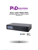
6.4 Remote Control
1
Power: Press the button to turn
On/O the unit.
2
Input Selection 1/2: Press 1/2 to
select HDMI input sources 1 or 2.
CR-37
POWER
1
2

11
6.5 RS-232 Pin Denition
Pin Dene TX / RX
1 N/C
2 TxD/RxD
3 RxD/TxD
4 NC
5 GND
6 NC
7 NC
8 NC
9 NC
Baud Rate: 115,200bps
Data bit: 8 bits
Parity: None
Flow Control: None
Stop Bit: 1
6.6 RS-232 Commands
COMMAND DESCRIPTION
POWER 00 Power O (Standby)
POWER 01 Power On
PORT 01 Select Input 1
PORT 02 Select Input 2
Note:
1. All the RS-232 command will be not executed unless followed with carriage
return and LF (Line Feed).
2. Commands are case-insensitive.

12
7. CONNECTION DIAGRAM

13
8. SPECIFICATIONS
8.1 Technical Specications
Video Bandwidth
340Mbps/10.2Gbps
Input ports
2 x HDMI, 1 x IR IN, 1 x LAN, 1 x USB
(Service only), 1 x RS-232
Output ports
1 x HDMI, 8 x CAT5e/6/7, 1 x IR OUT,
1 x L/R OUT, 1 x Optical OUT
Resolution
Up to 4Kx2K (3840x2160@24/25/30Hz &
4096x2160@24Hz)
HDMI Input Cable Distance
N/A
CAT5e/6/7 Output
Cable Distance
Up to 100m
IR Frequency
30~50kHz
ESD Protection
Human body model:
±8kV (air-gap discharge)
±4kV (contact discharge)
Power Supply
24V / 6.25A DC (US/EU standards, CE/
FCC/UL certied)
Dimensions (mm)
436 mm(W) x 249 mm(D) x 44 mm(H)/
Jacks Excluded
436 mm(W) x 256.2 mm(D) x 48 mm(H)/
Jacks Included
Weight(g)
3114
Chassis Material
Metal
Colour
Black
Operating Temperature
0˚C ~ 40˚C / 32 ˚F ~ 104 ˚F
Storage Temperature
-20˚C ~ 60˚C / -4 ˚F ~ 140 ˚F
Relative Humidity
20 ~ 90% RH (non-condensing)
Power Consumption
105W

14
8.2 CAT5e/6/7 Cable Specication
Cable
Type
Range Pixel clock
rate
Video Data
Rate
Supported Video
CAT5E/6/7 100 M <=225 MHZ <=5.3 GBPS
HD VIDEO
UP TO 1080P, 60 HZ, 36
BITS, 3D DATA RATES
LOWER THAN 5.3 GBPS
OR BELOW 225 MHZ
TMDS CLOCK.
70 M >225 MHZ > 5.3 GBPS
ULTRA HD
VIDEO
4K2K, 30HZ VIDEO
FORMATS
CAT6A/7 100 M >225 MHZ > 5.3 GBPS
ULTRA HD
VIDEO
4K2K, 30HZ VIDEO
FORMATS
9. ACRONYMS
ACRONYM COMPLETE TERM
4Kx2K 3840x2160 / 4096x2160
DTS Digital Theater System
EDID Extended Display Identication Data
HDCP High-bandwidth Digital Content Protection
HDMI High-Denition Multimedia Interface
HDTV High-Denition Television


CYP (UK) Ltd., Unit 7, Shepperton Business Park, Govett Avenue, Shepperton,
Middlesex, TW17 8BA
Tel: +44 (0) 20 3137 9180 | Fax: +44 (0) 20 3137 6279
Email: [email protected]
www.cypeurope.com
v1.00
/