Page is loading ...

DB9
OBD II Diagnostic Manual
Preliminary Issue

ASTON MARTIN LAGONDA LIMITED
Note: This version of the DB9 OBD II Diagnostic Manual is in the process of validation. The manual will
shortly be reissued to include all validation corrections.
Meanwhile, should any errors be identified, please call:
Aston Martin Technical Publications Department on 01926 644705.
Produced by the Technical Publications Department
ASTON MARTIN
Banbury Road
Gaydon
Warwick, CV35 0DB, England
Telephone: (01926) 644700 Fax: (01926) 644733
Issue 1 -April 2004 Part No. 701311

The OBDII Diagnostic System
Contents
April 2004 0-1
Contents
OBD II Diagnostic System 1-1
Engine Management 1-6
Diagnostic Equipment 1-8
Drive Cycle Routine 1-11
PCM and TCM Reset 1-13
CAN Bus Fault Analysis 1-15
Diagnostic Trouble Codes - Fault Analysis
P Code Fault Definition MIL Status
Page
No.
P0040 Oxygen Sensor Signals Swapped Bank 1 Sensor 1 / Bank 2 Sensor 1 MIL 2-2
P0041 Oxygen Sensor Signals Swapped Bank 1 Sensor 2 / Bank 2 Sensor 2 MIL 2-2
P0053 HO2S Heater Resistance (Bank 1, Sensor 1) MIL 2-4
P0054 HO2S Heater Resistance (Bank 1, Sensor 2) MIL 2-4
P0059 HO2S Heater Resistance (Bank 2, Sensor 1) MIL 2-4
P0060 HO2S Heater Resistance (Bank 2, Sensor 2) MIL 2-4
P0068 MAF v Throttle Correlation Check MIL 2-6
P0087 Fuel starvation MIL 2-8
P0102 Mass or Volume Air Flow Circuit Low Input MIL 2-10
P0103 Mass or Volume Air Flow Circuit High Input MIL 2-12
P0104 Intermittent MAF sensor signal MIL 2-14
P0107 Manifold Absolute Pressure/BARO Sensor Low Input MIL 2-16
P0108 Manifold Absolute Pressure/BARO Sensor High Input MIL 2-18
P0109 Manifold Absolute Pressure/BARO Sensor Intermittent MIL 2--20
P0112 Intake Air Temperature Sensor 1 Circuit Low Input MIL 2-22
P0113 Intake Air Temperature Sensor 1 Circuit High Input MIL 2-22
P0114 Intake Air Temperature Sensor Intermittent MIL 2-22
P0116 Engine Coolant Temperature Circuit Range/Performance MIL 2-24
P0117 Engine Coolant Temperature Circuit Low Input MIL 2-26
P0118 Engine Coolant Temperature Circuit High Input MIL 2-26
P0119 Engine Coolant Temperature Circuit Intermittent MIL 2-26
P0121 Throttle/Pedal Position Sensor A Circuit Range/Performance Non-MIL 2-28
P0122 Throttle/Pedal Position Sensor A Circuit Low Input MIL 2-28
P0123 Throttle/Pedal Position Sensor A Circuit High Input MIL 2-28
P0124 Throttle/Pedal Position Sensor A Intermittent MIL 2-30
P0128 Coolant Thermostat (Coolant Temp Below Regulating Temperature) MIL 2-32
P0132 O2 Circuit High Voltage (Bank 1, Sensor 1) MIL 2-34
P0133 O2 Circuit Slow Response (Bank 1, Sensor 1) MIL 2-36
P0135 O2 Heater Circuit (Bank 1, Sensor 1) MIL 2-38
P0138 O2 Circuit High Voltage (Bank 1, Sensor 2) MIL 2-40
P0141 O2 Heater Circuit (Bank 1, Sensor 2) MIL 2-38

The OBDII Diagnostic System
Contents
0-2 April 2004
P0148 Fuel Delivery Error. System too lean MIL 2-42
P0152 O2 Circuit High Voltage (Bank 2, Sensor 1) MIL 2-34
P0153 O2 Circuit Slow Response (Bank 2, Sensor 1) MIL 2-36
P0155 O2 Heater Circuit (Bank 2, Sensor 1) MIL 2-38
P0158 O2 Circuit High Voltage (Bank 2, Sensor 2) MIL 2-40
P0161 O2 Heater Circuit (Bank 2, Sensor 2) MIL 2-38
P0171 System Too Lean (Bank 1) MIL 2-44
P0172 System Too Rich (Bank 1) MIL 2-48
P0174 System Too Lean (Bank 2) MIL 2-44
P0175 System Too Rich (Bank 2) MIL 2-48
P0180 Fuel Temperature Sensor A Circuit MIL 2-52
P0182 Fuel Temperature Sensor Low Input MIL 2-52
P0183 Fuel Temperature Sensor High Input MIL 2-52
P0190 Fuel Rail Pressure Sensor Midrange Fault MIL 2-54
P0191 Fuel Rail Pressure Sensor Range/Performance MIL 2-56
P0192 Fuel Rail Pressure Sensor Low Input MIL 2-58
P0193 Fuel Rail Pressure Sensor High Input MIL 2-60
P0201 Injector Circuit / Open - Cylinder 1 MIL 2-62
P0202 Injector Circuit / Open - Cylinder 2 MIL 2-62
P0203 Injector Circuit / Open - Cylinder 3 MIL 2-62
P0204 Injector Circuit / Open - Cylinder 4 MIL 2-62
P0205 Injector Circuit / Open - Cylinder 5 MIL 2-62
P0206 Injector Circuit / Open - Cylinder 6 MIL 2-62
P0218 Transmission fluid temperature Non-MIL 2-64
P0221 Throttle/Pedal Position Switch B Circuit Range/Performance MIL 2-28
P0222 Throttle/Pedal Position Sensor B Circuit Low Input MIL 2-28
P0223 Throttle/Pedal Position Sensor B Circuit High Input MIL 2-28
P0224 Throttle/Pedal Position Sensor B Circuit Intermittent MIL 2-66
P0300 Random Misfire Detected MIL 2-68
P0301 Cylinder 1 Misfire Detected MIL 2-72
P0302 Cylinder 2 Misfire Detected MIL 2-72
P0303 Cylinder 3 Misfire Detected MIL 2-72
P0304 Cylinder 4 Misfire Detected MIL 2-72
P0305 Cylinder 5 Misfire Detected MIL 2-72
P0306 Cylinder 6 Misfire Detected MIL 2-72
P0307 Cylinder 7 Misfire Detected MIL 2-72
P0308 Cylinder 8 Misfire Detected MIL 2-72
P0309 Cylinder 9 Misfire Detected MIL 2-72
P0310 Cylinder 10 Misfire Detected MIL 2-72
P0311 Cylinder 11 Misfire Detected MIL 2-72
P Code Fault Definition MIL Status
Page
No.

The OBDII Diagnostic System
Contents
April 2004 0-3
P0312 Cylinder 12 Misfire Detected MIL 2-72
P0315 Crankshaft Position System Variation Not Learned MIL 2-76
P0316 Misfire Detected On Startup (First 1000 Revolutions) MIL 2-72
P0320 Ignition Engine Speed Input Circuit Fault MIL 2-78
P0322 Lost CPS Signal MIL 2-80
P0340 Cylinder Identification Sensor A Circuit (Bank 1) MIL 2-82
P0345 Cylinder Identification Sensor A Circuit (Bank 2) MIL 2-82
P0351 Ignition Coil A Primary/Secondary Circuit MIL 2-84
P0352 Ignition Coil B Primary/Secondary Circuit MIL 2-84
P0353 Ignition Coil C Primary/Secondary Circuit MIL 2-84
P0354 Ignition Coil D Primary/Secondary Circuit MIL 2-84
P0355 Ignition Coil E Primary/Secondary Circuit MIL 2-84
P0356 Ignition Coil F Primary/Secondary Circuit MIL 2-84
P0420 Catalyst System Efficiency Below Threshold (Bank 1) MIL 2-86
P0430 Catalyst System Efficiency Below Threshold (Bank 2) MIL 2-88
P0442 Evaporative Emission System Leak Detected (small leak) MIL 2-90
P0443 Evaporative Emission System Purge Control Valve Circuit MIL 2-92
P0446 Evaporative Emission System Canister Vent Valve Circuit MIL 2-94
P0451 Evaporative Emission System Pressure Sensor Range/Performance MIL 2-96
P0452 Evaporative Emission System Pressure Sensor/Switch Low Input MIL 2-98
P0453 Evaporative Emission System Pressure Sensor/Switch High Input MIL 2-100
P0454 Evaporative Emission System Pressure Sensor/Switch Intermittent Input MIL 2-102
P0455 Evaporative Emission System Leak Detected (gross leak/no flow) MIL 2-104
P0456 Evaporative Emission System Leak Detected (very small leak) MIL 2-106
P0457 Evaporative Emission System Leak Detected (fuel cap loose/off) MIL 2-108
P0460 Fuel Level Sensor A Circuit MIL 2-110
P0461 Fuel Level Sensor A Circuit Range/Performance MIL 2-112
P0462 Fuel Level Sensor A Circuit Low Input MIL 2-114
P0463 Fuel Level Sensor A Circuit High Input MIL 2-116
P0480 Fan Control Circuit MIL 2-118
P0483 Fan Performance MIL 2-118
P0500 Output Shaft Speed Sensor Short To Supply Non-MIL 2-120
P0501 Output Shaft Speed Sensor Too High Compared to Wheel Speed MIL 2-120
P0502 Output Shaft Speed Sensor Short To Ground/Open Circuit Non-MIL 2-120
P0503 Vehicle Speed Sensor A Intermittent/Erratic/High MIL 2-120
P0505 Idle Air Control System MIL 2-122
P0506 Idle Air Control System RPM Lower Than Expected MIL 2-122
P0507 Idle Air Control System RPM Higher Than Expected MIL 2-122
P0532 A/C Refrigerant Pressure Sensor A Circuit Low Input MIL 2-124
P0533 A/C Refrigerant Pressure Sensor A Circuit High Input MIL 2-124
P Code Fault Definition MIL Status
Page
No.

The OBDII Diagnostic System
Contents
0-4 April 2004
P0552 Power Steering Pressure Sensor/Switch Circuit Low Input MIL 2-126
P0553 Power Steering Pressure Sensor/Switch Circuit High Input MIL 2-128
P0562 System Voltage Low MIL 2-130
P0563 System Voltage High MIL 2-130
P0579 Cruise Control Multi-Function Input A Circuit Range/Performance MIL 2-132
P0581 Cruise Control Multi-Function Input A Open Circuit MIL 2-132
P060D Throttle Pedal Imbalance Primary to secondary MIL 2-134
P0602 Powertrain Control Module (VID Block) Error MIL 2-136
P0603 Powertrain Control Module Keep Alive Memory (KAM) Error MIL 2-138
P0605 Powertrain Control Module Read Only Memory (ROM) Error MIL 2-140
P0606 ECM / PCM Processor MIL 2-142
P0613 TCM Processor Watchdog error MIL 2-144
P0614 ECM / TCM IncompatibleCAN Level MIL 2-146
P0620 Alternator Control Circuit MIL 2-148
P0622 Alternator Field Terminal Circuit MIL 2-148
P062F Transmission Internal module EEPROM Error MIL 2-150
P0634 PCM / ECM / TCM Internal Temperature Too High Or Sensor Failure MIL 2-152
P0641 Transmission Sensor Supply Voltage too High or too Low MIL 2-154
P0645 A/C Clutch Relay Control Circuit MIL 2-156
P0657 Transmission Pressure Regulator and Solenoid Voltage Circuit / Open MIL 2-158
P0658 Transmission Pressure Regulator and Solenoid Voltage Circuit Low MIL 2-158
P0659 Transmission Pressure Regulator and Solenoid Voltage Circuit High MIL 2-158
P0667 TCM Internal Temperature Sensor Too High/Low MIL 2-160
P0701 Transmission Control System Failure. A Combination of Other Errors. MIL 2-162
P0705 Transmission PRDN Request Invalid. CAN and Serial Line Invalid . MIL 2-164
P0711 Transmission Fluid Temperature Sensor A Circuit Range/Performance MIL 2-166
P0712 Transmission Fluid Temperature Sensor A Circuit Low Input MIL 2-166
P0713 Transmission Fluid Temperature Sensor A Circuit High Input MIL 2-166
P0714 Transmission Fluid Temperature Sensor A Circuit Intermittent MIL 2-166
P0715 Turbine/Input Shaft Speed Sensor Circuit Short To Supply MIL 2-168
P0716 Turbine/Input Shaft Speed Sensor Circuit Too High/Too Low MIL 2-168
P0717 Turbine/Input Shaft Speed Sensor Circuit Short to Ground/O. Circuit MIL 2-168
P0720 Output Shaft Speed Sensor Circuit MIL 2-170
P0721 Output Shaft Speed Sensor Circuit Range/Performance MIL 2-170
P0722 Output Shaft Speed Sensor Circuit No Signal MIL 2-170
P0725 Engine Speed Input Circuit Plausibility Error MIL 2-172
P0729 Gear 6 Incorrect Ratio. Plausibility error. MIL 2-174
P0730 Incorrect Gear Ratio. Plausibility error. Non-MIL 2-174
P0731 Gear 1 Incorrect Ratio. Plausibility error. MIL 2-174
P0732 Gear 2 Incorrect Ratio. Plausibility error. MIL 2-174
P Code Fault Definition MIL Status
Page
No.

The OBDII Diagnostic System
Contents
April 2004 0-5
P0733 Gear 3 Incorrect Ratio. Plausibility error. MIL 2-174
P0734 Gear 4 Incorrect Ratio. Plausibility error. MIL 2-174
P0735 Gear 5 Incorrect Ratio. Plausibility error. MIL 2-174
P0736 Reverse Gear Incorrect Ratio MIL 2-176
P0740 Torque Converter Clutch Solenoid Circuit / Open MIL 2-178
P0741 Torque Converter Clutch Solenoid Circuit Performance Or Stuck Off MIL 2-180
P0770 Shift Solenoid E Open Circuit MIL 2-314
P0771 Mechanical Failure of Shift Solenoid Valve MV1 or MV2 MIL 2-182
P0780 Gear Load error Too High or No Change Non-MIL 2-184
P0781 Gear load error during 1-2 shift. Clutch does not close. MIL 2-184
P0782 Gear load error during 2-3 shift. Clutch does not close. MIL 2-184
P0783 Gear load error during 3-4 shift. Clutch does not close. MIL 2-184
P0784 Gear load error during 4-5 shift. Clutch does not close. MIL 2-184
P0812 Reverse Input Circuit MIL 2-186
P0815 Upshift Switch Circuit MIL 2-188
P0816 Downshift Switch Circuit MIL 2-188
P081C Reverse input switch circuit error on manual transmission MIL 2-186
P081D Neutral input switch circuit error on manual transmission MIL 2-186
P0826 Up and Down Switch Input Circuit via CAN Error MIL 2-190
P0829 Gear load error during 5-6 shift. Clutch does not close. MIL 2-184
P0830 Clutch Pedal Switch A Circuit MIL 2-192
P0833 Clutch Pedal Switch B Circuit MIL 2-192
P0850 Parklock Sensor Fault. Non-MIL 2-194
P0853 Drive Switch Input Circuit MIL 2-186
P0860 TCM To PCM Heartbeat Signal Open Circuit Non-MIL 2-196
P0861 TCM To PCM Heartbeat Signal Short To Ground/Open Circuit Non-MIL 2-196
P0862 TCM To PCM Heartbeat Signal Short To Supply Non-MIL 2-196
P0863 Serial Backup Line Time Out (PRND) Non-MIL 2-198
P0960 Pressure Control Solenoid A Circuit / Open MIL 2-178
P0961 Pressure Control Solenoid A Circuit Too High/Low MIL 2-200
P0962 Pressure Control Solenoid A Circuit O. Circuit/Short To Ground MIL 2-178
P0963 Pressure Control Solenoid A Control Circuit Short to Supply Non-MIL 2-202
P0972 Shift Solenoid A Control Circuit Too High/Low MIL 2-200
P0973 Shift Solenoid A Control Circuit Open Circuit/Short to Ground MIL 2-178
P0974 Shift Solenoid A Control Circuit Short To Supply MIL 2-202
P0975 Shift Solenoid B Control Circuit Too High/Low MIL 2-200
P0976 Shift Solenoid B Control Circuit Open Circuit/Short to Ground MIL 2-178
P0977 Shift Solenoid B Control Circuit Short To Supply MIL 2-202
P0978 Shift Solenoid C Control Circuit Too High/Low MIL 2-200
P0979 Shift Solenoid C Control Circuit Open Circuit/Short to Ground MIL 2-178
P Code Fault Definition MIL Status
Page
No.

The OBDII Diagnostic System
Contents
0-6 April 2004
P0980 Shift Solenoid C Control Circuit Short To Supply MIL 2-202
P0981 Shift Solenoid D Control Circuit Too High/Low MIL 2-200
P0982 Shift Solenoid D Control Circuit Open Circuit/Short to Ground MIL 2-178
P0983 Shift Solenoid D Control Circuit Short to Supply MIL 2-202
P0985 Shift Solenoid E Control Circuit Low Short to Ground/Open Circuit MIL 2-204
P0986 Shift Solenoid E Control Circuit Short To Supply MIL 2-206
P0998 Shift Solenoid F Control Circuit Short to Ground/Open Circuit MIL 2-204
P0999 Shift Solenoid F Control Circuit Short To Supply MIL 2-206
P1000 OBD Systems Readiness Test Not Complete MIL 2-208
P1001 KOER Not Able to Complete, KOER Aborted MIL 2-209
P1101 Mass Air Flow Sensor Out Of Self Test Range MIL 2-210
P1116 Engine Coolant Temperature Sensor Out Of Self Test Range MIL 2-212
P1127 Exhaust Temperature Out of Range, O2 Sensor Tests Not Completed MIL 2-214
P115C OBDII fault code for Passive Disable Driver Interface triggered MIL 2-216
P1233 Fuel Pump Driver Module Disabled or Off Line MIL 2-218
P1235 Fuel Pump Driver Module Range or perfomance MIL 2-218
P1237 Fuel Pump Secondary Circuit (Fuel Pump Driver Module) MIL 2-218
P1270 Engine RPM or Vehicle Speed Limiter Reached MIL 2-220
P1336 Crankshaft/Camshaft Sensor Range/Performance MIL 2-222
P1397 Battery Voltage Out of Range During KOER/KOEO MIL 2-224
P1450 Unable to Bleed Up Fuel Tank Vacuum MIL 2-226
P1463 A/C Pressure Sensor Insufficient Pressure Change MIL 2-228
P1464 A/C Demand Out Of Self Test Range MIL 2-230
P1488 Exhaust (muffler) Bypass Control Circuit MIL 2-232
P1500 Vehicle Speed Sensor MIL 2-234
P1501 Vehicle Speed Sensor Out Of Self Test Range MIL 2-234
P1550 Power Steering Pressure Sensor Out Of Self Test Range MIL 2-236
P1572 Brake Pedal Switch Circuit MIL 2-238
P1573 Throttle Position Not Available MIL 2-240
P1574 Throttle Position Sensor Outputs Disagree MIL 2-240
P1578 ETC Power Less Than Demand MIL 2-242
P1579 ETC In Power Limiting Mode MIL 2-242
P1585 Throttle Control Malfunction MIL 2-244
P1587 Throttle Control Modulated Command Malfunction MIL 2-244
P1603 Transmission EPROM Checksum Error MIL 2-246
P1605 Battery Buffered RAM Fault (Keep Alive Memory) Non-MIL 2-248
P1608 Level 2 Software Monitoring (Internal Error) MIL 2-250
P1633 Fault flag Indicating a Low/Lack Of Keep Alive Memory Voltage MIL 2-252
P1635 Tire/Axle Out of Acceptable Range MIL 2-254
P1639 Vehicle ID Block Corrupted, Not Programmed MIL 2-256
P Code Fault Definition MIL Status
Page
No.

The OBDII Diagnostic System
Contents
April 2004 0-7
P1674 Control Module Software Corrupted MIL 2-258
P1700 Transmission Indeterminate Failure (Failed to Neutral) MIL 2-260
P1703 Brake Switch Out Of Self Test Range MIL 2-262
P1707 Parklock Engage/Release Failure (Without Driver Request) Non-MIL 2-264
P1709 Park Neutral Position Switch Out Of Self Test Range MIL 2-266
P1712 Transmission Torque Reduction Request Signal MIL 2-268
P1719 Engine Torque Signal (CAN) to Transmission Error MIL 2-270
P1745 Line Pressure Solenoid Fault MIL 2-272
P1789 Low Battery Voltage with Turbine Speed (7V-9V) MIL 2-274
P1793 Transmission Module Battery Voltage Too Low <7V MIL 2-276
P1794 Battery Voltage Too High >16V MIL 2-278
P1796 CAN Controller Circuit (Bus off) MIL 2-280
P1797 CAN TCM/ECM Position Circuit Malfunction MIL 2-282
P1798 CAN TCM/CEM/DIM Circuit Malfunction MIL 2-284
P1799 CAN TCM/ABS Circuit Malfunction Non-MIL 2-284
P1920 Engine Overspeed for Transmission. Plausibility Error MIL 2-286
P1934 Wheel Speed Signal Failure/Not Plausable Non-MIL 2-288
P1935 Invalid Brake Signal Non-MIL 2-290
P2105 Throttle Actuator Control System - Forced Engine Shutdown MIL 2-292
P2106 Throttle Actuator Control System - Forced Limited Power MIL 2-294
P2107 Throttle Actuator Control Module Processor MIL 2-296
P2111 Throttle Actuator Control System - Stuck Open MIL 2-298
P2112 Throttle Actuator Control System - Stuck Closed MIL 2-298
P2121 Throttle/Pedal Position Sensor/Switch D Circuit Range/Performance MIL 2-300
P2122 Throttle/Pedal Position Sensor/Switch D Circuit Low Input MIL 2-300
P2123 Throttle/Pedal Position Sensor/Switch D Circuit High Input MIL 2-300
P2124 Throttle/Pedal Position Sensor/Switch D Circuit Intermittent MIL 2-300
P2126 Throttle/Pedal Position Sensor/Switch E Circuit Range/Performance MIL 2-300
P2127 Throttle/Pedal Position Sensor/Switch E Circuit Low Input MIL 2-300
P2128 Throttle/Pedal Position Sensor/Switch E Circuit High Input MIL 2-300
P2129 Throttle/Pedal Position Sensor/Switch E Circuit Intermittent MIL 2-300
P2135 Throttle/Pedal Position Sensor/Switch A / B Voltage Correlation MIL 2-302
P2138 Throttle/Pedal Position Sensor/Switch D / E Voltage Correlation MIL 2-304
P2162 Vehicle Speed Sensor A / B Correlation MIL 2-306
P2195 O2 Sensor Signal Stuck Lean - Bank 1, Sensor 1 MIL 2-308
P2196 O2 Sensor Signal Stuck Rich - Bank 1, Sensor 1 MIL 2-308
P2197 O2 Sensor Signal Stuck Lean - Bank 2, Sensor 1 MIL 2-308
P2198 O2 Sensor Signal Stuck Rich - Bank 2, Sensor 1 MIL 2-308
P2270 O2 Sensor Signal Stuck Lean - Bank 1, Sensor 2 MIL 2-308
P2271 O2 Sensor Signal Stuck Rich - Bank 1, Sensor 2 MIL 2-308
P Code Fault Definition MIL Status
Page
No.

The OBDII Diagnostic System
Contents
0-8 April 2004
P2272 O2 Sensor Signal Stuck Lean - Bank 2, Sensor 2 MIL 2-308
P2273 O2 Sensor Signal Stuck Rich - Bank 2, Sensor 2 MIL 2-308
P260F Neural Net Processor Reports ROM Checksum Error MIL 2-310
P2706 Shift Solenoid F Open Circuit MIL 2-312
P2762 Torque Converter Clutch Pressure Solenoid Circuit Too High/Low MIL 2-200
P2763 Torque Converter Clutch Pressure Solenoid Circuit Short To Supply MIL 2-314
P2764 Torque Converter Clutch Solenoid Circuit Short To Ground/O. Circuit MIL 2-314
P2779 Downshift Switch Circuit Non-MIL 2-316
P2800 Shift By Wire Transmission Range Sensor Circuit Fault MIL 2-318
P2801 Shift By Wire Transmission Range Sensor Circuit Range or Perfomance Non-MIL 2-318
P2805 Position Information Fault On Serial Backup Line Non-MIL 2-320
P2812 Shift Solenoid G (Park Lock) Open Circuit Non-MIL 2-322
P2814 Shift Solenoid G (Park Lock) Short to Ground/Open Circuit MIL 2-322
P2815 Shift Solenoid G (Park Lock) Short to Supply Non-MIL 2-322
P Code Fault Definition MIL Status
Page
No.

The OBDII Diagnostic System
Contents
May 2002 1-1
Introduction
The operation of the internal combustion engine depends on the ability to rapidly and accurately control several
variables. The two main variables are; the quantity of fuel passed to the cylinder and the timing of ignition. Basic
control of these variables is exercised by the Powertrain Control Modules (Primary and Secondary PCMs) which
contain all the software to supervise and control the engine management system. The PCMs also contain the di-
agnostic software (the Diagnostic Executive) required to detect any system malfunctions which could increase
harmful emissions.
The Diagnostic Executive is the computer programme which monitors aspects of emission related engine perform-
ance. This programme controls all the monitor sequences, records DTCs, lights the MIL lamp and memorises
freeze frame data for later analysis
The freeze frame data may be accessed using the World Diagnostic System (WDS) or other scan tool. The stored
data describes engine conditions at the time the malfunction was detected, such as the state of the engine, state
of fuel control, spark, rpm, load and warm up status. Previously stored conditions will be replaced only if a fuel
or misfire malfunction is detected.
In order to pass all diagnostic monitors, a new vehicle or one in which the PCM memory has been cleared must
be driven sufficiently (a complete drive cycle) to clear all component checks. A P1000 code will be recorded until
all sections of the OBD II drive cycle are completed. The presence of a P1000 code is not a cause for concern
unless other codes are present. The drive cycles are described later in this section.
The following monitors are included in the diagnostic software:
• Heated Oxygen Sensor (HO2S) Monitor
• Catalyst Efficiency Monitor
•Misfire Detection Monitor
• Fuel System Monitor
• Comprehensive Component Monitor
NB: TRIP - In the following descriptions the term trip is defined as successful completion of all monitors without
detecting any fault which would illuminate the MIL lamp.

The OBDII Diagnostic System
Comprehensive Component Monitor
1-2 May 2002
Comprehensive Component Monitor
The comprehensive component monitor is a self test strategy that detects malfunctions of any electronic power-
train component which may have an effect upon engine emission levels.
The inputs monitored include the PCM Identification, Inlet Air Temperature (IAT), Fuel Tank Pressure (FTPT), Cyl-
inder Identification (CID), Fuel Level Indicator (FLI), Crankshaft Position (CKP), Vehicle Speed Sensor (VSS), Mass
Air Flow Meter (MAF), Engine Coolant Temperature (ECT), Throttle Potentiometer (TP) sensors and Throttle Pedal
Position (TPP) sensors.
Outputs monitored by the comprehensive component monitor include the Ignition System, Fuel Pump, Fan Con-
trol, Vapour Management Valves (VMV), Canister Vent Valve (CANVNT), all fuel injectors, the A/C cut-out relay
(WAC) and the Throttle Controller.
An input component malfunction is declared if there is a lack of continuity, the signal is out of range, or if the sig-
nal is not in the correct relationship to another associated signal.
An output component malfunction is declared if there is a lack of continuity or if an expected output response to
an PCM command does not occur.
In the comprehensive component monitor, when a malfunction has been present for two drive cycles, the rele-
vant DTC is stored in the PCMs and the MIL is turned on.
The MIL is turned off after three consecutive trips without the same malfunction being detected provided that no
other DTCs are stored which would independently turn on the MIL. The DTC will be erased from memory after
40 warm-up cycles without the malfunction being detected after the MIL is turned off. The code may also be
cleared by performing an PCM reset using the Diagnostic System (WDS) or a generic Scan Tool.
During a drive cycle, the individual monitor checks will be completed and entered into the PCM memory. The
OBDII Readiness Test screen on the WDS may be used to show which particular monitors have completed since
the last PCM reset. All monitors must successfully complete to clear a P1000 code (P1000 = OBD II System
Checkout Incomplete).

The OBDII Diagnostic System
System and Component Monitors
May 2002 1-3
System and Component Monitors
Heated Oxygen Sensor Monitor
OBD II regulations require monitoring of the upstream heated oxygen sensors to detect when deterioration of the
sensor has exceeded emission thresholds. Additional oxygen sensors are located downstream to determine the
efficiency of the catalyst. The downstream sensors are of a different type to those used for fuel control. The front
and rear sensors are not interchangeable. They are monitored to determine if a voltage is generated. That voltage
is then compared to values in memory to determine if the catalyst efficiency is in range.
Operation
The fuel control system attempts to maintain an air/fuel ratio of approximately14.7:1. The PCM uses the input from
the upstream HO2S sensors to fine tune the air fuel mixture.
The upstream heated oxygen sensors are mounted in the exhaust flow between the engine and the catalytic con-
vertors. The sensors operate between zero and one volt output depending on the oxygen content of the exhaust
gasses. Lean air/fuel mixture will cause a sensor voltage of 0 - 0.4 volts. Rich air/fuel mixture will cause a voltage
of 0.6 - 1.0 volts. The ideal air/fuel mixture would cause a sensor voltage of 0.4 - 0.6 volts to be generated. The
actual sensor voltage will fluctuate as the system attempts to reach optimum air/fuel mixture under constantly
changing conditions.
The following HO2S system checks are performed:
Upstream sensors are checked by changing the air fuel ratio and monitoring the sensor response.
Downstream sensors are monitored by noting the voltage change for changes in downstream oxygen content.
All sensors are monitored for overvoltage conditions
Sensor heaters are checked by turning them on and off and looking for changes in the current they draw.
When a HO2S malfunction is detected for two drive cycles, the DTC is stored in memory and the MIL is turned
on. The MIL will be turned off after three consecutive trips without the same malfunction being detected, provid-
ing that no other malfunctions are present which would independently turn on the MIL. The DTC will be erased
from memory after 40 warm-up cycles provided that the same DTC is not detected. The code may also be cleared
by performing a PCM reset.
Catalyst Efficiency Monitor
The catalyst efficiency monitor determines when the catalyst efficiency has fallen below the minimum efficiency
requirements.
Operation
Upstream and downstream oxygen sensor signals are compared during a range of speed/load conditions. The cat-
alyst must be able to process the exhaust gases such that the rear oxygen sensors are prevented from switching in
the same way as the front.
When a catalyst efficiency malfunction is detected for two drive cycles, the DTC is stored in memory and the MIL
is turned on. The MIL will be turned off after three consecutive trips without the same malfunction being detected,
providing that no other malfunctions are present which would independently turn on the MIL. The DTC will be
erased from memory after 40 warm-up cycles provided that the same DTC is not detected. The code may also be
cleared by performing an PCM reset or a DTC ‘CLEAR’ using WDS.

The OBDII Diagnostic System
System and Component Monitors
1-4 May 2002
Fuel System Monitor
The fuel system monitor is a self test strategy within the PCM that monitors the adaptive fuel table. This table is
used by the fuel control system to compensate for normal variability of the fuel system components due to age or
wear. If the fuel system appears biased lean or rich, the adaptive fuel values will be shifted to remove the bias.
Operation
The adaptive fuel system uses the upstream oxygen sensor outputs as its primary input. The system also is capable
of adapting fuelling requirements based on, Air Temperature, Coolant Temperature and Mass Air Flow.
As the fuel control and air metering components age or vary from nominal values, the adaptive fuel strategy learns
corrections while in closed loop operation. These corrections are stored in a table called 'Long Term Fuel Trim'.
The table resides in KAM (Keep Alive Memory) and is used to correct fuel delivery while in open or closed loop
control.
As components continue to change, the table will reach its adaptive limit and can no longer cope with additional
changes in fuelling components. Further changes in the fuel system components will cause deviation in the closed
loop parameter called 'Short Term Fuel Trim'. As this deviation in short term fuel trim approaches 1.5 times the
applicable standard, fuel/air control suffers and emissions may increase. At this point, a fuel system fault is de-
clared and a DTC is stored.
The fuel system tests are only run when the following preconditions are satisfied, engine rpm within acceptable
range, air mass within calibrated limits, engine coolant temperature indicates the engine fully warmed up, steady
throttle opening at a road speed of 30 - 45 m.p.h. Idle and deceleration performances are excluded from fuel sys-
tem testing.
In the fuel system monitor, when a malfunction has been present for two drive cycles, the DTC is stored and the
MIL lamp is turned on. At the same time, freeze frame data will be stored as described in the system overview. In
order to provide the maximum information for fault analysis, the range of freeze frame data stored when a fuel
system monitor fault occurs exceeds that required by the Air Resources Board.
The MIL is turned off after three consecutive drive cycles without the same DTC being detected provided that no
other DTCs are recorded which would independently turn on the MIL. The DTC will be erased from memory after
40 trips provided that the same DTC is not detected. The code may also be cleared by performing a PCM reset.

The OBDII Diagnostic System
System and Component Monitors
May 2002 1-5
Purge System Monitor
Tests the integrity and operation of the evaporative loss purge system.
Operation
Primary PCM - After an overnight soak, during steady state driving, the canister vent valve is closed and the purge
system pulls a light vacuum in the fuel tank. The time taken for the vacuum to decay is measured and compared
to calibrated limits. The results indicate whether the fuel vapour system is leak proof.
Secondary PCM - During vehicle acceleration, the engine fuelling requirements are stabilised and then the vapour
management valve is opened. If the carbon canisters contain fuel vapour, it will be drawn into the inlet manifold.
The fuelling correction required to rectify the fuel imbalance caused by the additional fuel vapour is noted. The
adjustment required is used as an indicator of correct purge system flow.
Misfire Detection Monitor
Misfire is defined as the lack of proper combustion in the cylinder due to the absence of spark, poor fuel metering
or poor compression. Any combustion occurring at an improper time is also defined as a misfire.
Misfires are detected by the Neural Net Misfire Monitor which checks various engine operating conditions (par-
ticularly crankshaft acceleration) and compares them to data held in PCM memory.

The OBDII Diagnostic System
The EECV Engine Management System
1-6 May 2002
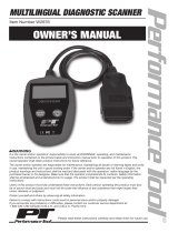
Engine Management - Schematic Diagram

The OBDII Diagnostic System
The EECV Engine Management System
May 2002 1-7
Description of Components
Powertrain Control Modules (PCMs) - Primary and Secondary
The engine management system is controlled by the Powertrain Control Modules (PCMs), which receive signals
from the sensors, compares them to the required standards and then modify the fuel and ignition settings to main-
tain an optimum, stoichiometric, fuel and air mixture under all conditions. Sensor information is supplied to the
Control Module Inputs, and control commands are issued through the Control Module Outputs. The PCMs are
located one under each front wing.
The Mass Air Flow Sensor (MAF)
The Mass Air Flow Sensor (MAF), measures the quantity of air drawn into the engine and reports to the PCM.
The Air Temperature Sensor (IAT)
An Inlet Air Temperature Sensor (IAT), is located inside each mass airflow meter and measures the temperature of
the air entering either side of the engine. These sensors are fitted so that the engine management system can com-
pensate for air density changes.
The Engine Coolant Temperature Sensors (ECT)
The Engine Coolant Temperature Sensor (ECT), monitors the coolant temperature and reports to the primary PCM.
The secondary PCM receives the current temperature information from the primary PCM over the CAN bus.
The Fuel Pumps
The Fuel Pumps, situated in the fuel tank, supply fuel to the Fuel Rails. The fuel pressure at the fuel rails is regulated
by changing the run speed of the fuel pumps.
Fuel Injectors
The twelve Injector solenoids are operated by the PCMs in sequence to inject fuel into the area behind each inlet
valve. The volume of fuel injected is governed by the length of time each injector solenoid is actuated and the
pressure in the fuel rail.
Ignition Coils
Ignition is by long life Spark Plugs supplied with HT voltage from the Ignition Coils mounted on each plug. The
timing of ignition is varied by the PCM according to vehicle speed and engine load.
Catalytic Convertor / Heated Oxygen Sensors (H02S)
The combustion gases, after passing through the exhaust manifolds, enter the Catalytic Convertors, where the
quality of the exhaust gas emission is modified. The quality of the exhaust gas emission is constantly checked by
the four Upstream Heated Oxygen Sensors (H02S1 on either bank), which are situated at the entrance of the cat-
alysts. The catalyst efficiency is checked using four Downstream Heated Oxygen Sensors (H02S2 on either bank).
By comparing the signal outputs of pre and post catalyst heated oxygen sensors the PCM can make corrections to
the fuel and ignition settings as necessary. The sensors contain integral heaters which accelerate the warming-up
of the sensors to enable a rapid correction of initial settings which may be causing the emission of low quality
exhaust gases.

The OBDII Diagnostic System
Diagnostic Equipment
1-8 May 2002
Throttle Position Sensor (TP)
Throttle position is detected by the Throttle Position Sensors (TP) mounted on each throttle body. These sensors
report to the PCMs.
Throttle Pedal Position Sensor (PPS)
Throttle pedal position is detected by two Throttle Pedal Position Sensors (PPS) mounted in the throttle pedal as-
sembly. These sensors report the PPS signal to the PCMs. The pedal position is constantly verified by means of a
rationality check between the three potentiometer readings. If any reading goes out of normal range, the in range
readings are used and a fault is flagged on the out of range potentiometer.
Throttle Motors
Motor driven throttles are mounted on the left and right inlet manifolds. As the driver moves the throttle pedal,
the throttle pedal signals change, the PCMs receive the revised position signals and send drive signals to the throt-
tle motors to drive the throttles to the new position.
Crankshaft Position Sensor (CKP)
Engine speed is measured from the pulse timing of the two Crankshaft Position Sensors (CKP). CKP signals are in-
put to the primary and secondary Powertrain Control Modules.
Camshaft Position Sensor - Cylinder Identification Sensor (CID)
Engine position is determined by using the two Camshaft Position Sensor (CID) signals. CMP signals are input to
the primary and secondary Powertrain Control Modules.
Using the CKP and CID signals, the PCMs can accurately control the start time for ignition/fuel injection events.
Evaporative Emission Canister
The Fuel Tank, may be filled to 90% of the actual measured capacity; the 10% air volume above the fuel is vented
to atmosphere through the Evaporative Emission Canister. The carbon element in this canister absorbs any dis-
placed fuel vapour. As fuel is withdrawn from the tank, air is drawn in through the canisters to avoid creating a
vacuum in the fuel tank.
When the fuel laden air in the tank expands at higher temperatures, pressure is relieved by allowing the displaced
air to vent through the canister which retains any suspended fuel vapour.
During normal engine running, the vapour management valve allows air flow through the carbon canister and
into the inlet manifolds, constantly purging any petrol vapour and burning it in the normal combustion process.
The Vapour Management Valve
The Vapour Management Valve, is controlled by the Primary PCM and open the canister line to inlet manifold
vacuum; when the inlet manifold vacuum is sufficient, the vapour management valve will open. Air can then flow
through the carbon canister, carrying fuel vapour to the inlet manifold and into the engine.
Diagnostic Equipment
The Aston Martin Diagnostic System (WDS) is the principal diagnostic tool used by Aston Martin franchised deal-
ers. Non-franchised dealers will require the AML WDS or a compatible scan tool. The WDS installation and use
is described in a separate publication. The WDS connects to the diagnostic sockets.

The OBDII Diagnostic System
Diagnostic Sockets
May 2002 1-9
Diagnostic Sockets Location and Use
The two diagnostic sockets are located on the drivers side of the centre console. Note that the sockets change
sides between left and right hand drive vehicles. The following systems are accessed from each socket:
Body Socket - Closest to the Centre Stack
Airbag and Seat Belt Pretensioner System
Security System
Body Module
Transmission Control Unit (datalogging and DTC read)
Engine Socket - Furthest from the Centre Stack
Powertrain Control Module (PCM)
Transmission Control Module (TCM) (OBD II DTC read via the PCM)
Passive Anti-Theft System
Anti-Lock Braking System
The pin connections to each socket are shown on the following page:
Body
Diagnostic
Socket
Engine
Diagnostic
Socket
PRN
D
CRUISE
000000
MILES
000
T1
0

The OBDII Diagnostic System
Diagnostic Sockets
1-10 May 2002
Diagnostic Sockets - Pin Location and Function
Engine Socket (Drivers Side)
Pin Function Used by:
1
2
3
4 Power Ground All
5 Chassis Ground All
6 CAN Link (+) High Speed
7
8
9 +12V Ignition Supply Input Power/Signal
10
11 No Connection
12 No Connection
13 FEPS Flash reprogramming
14 CAN Link (-) High Speed
15 No Connection
16 12V Battery All
Body Socket (Passenger Side)
Pin Function Used by:
1
2
3 CAN Link (+) Low Speed
4 Power Ground All
5 Chassis Ground
6 CAN Link (+) High Speed
7K line ISO 9141
8K line TCM
9 +12V Ignition Supply
10
11 CAN Link (-) Low Speed
12 No connection
13 No connection
14 CAN Link (-) High Speed
15
16 12V Battery (unswitched) All
16
16 9
81
9
39-046
81
/