
Instructions and warnings for the fitter
Istruzioni ed avvertenze per l’installatore
Instructions et recommandations pour l’installateur
Anweisungen und Hinweise für den Installateur
Instrucciones y advertencias para el instalador
Instrukcje i uwagi dla instalatora
Aanwijzingen en aanbevelingen voor de installateur
For projecting
and non-projecting
up-and-over doors,
and sectional doors
Spin10KCE
Spin11KCE

2
Spin10KCE
Spin11KCE
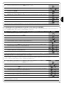
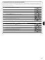
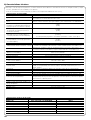
Table of contents: page
1 Warnings 3
2 Product description 3
2.1 Operating limits 4
2.2 Typical system 5
2.3 List of cables 5
3 Installation 6
3.1 Preliminary checks 6
3.2 Fitting SPIN 6
3.2.1 Assembly of guide supplied with SPIN10KCE 7
3.2.2 SNA11 guide assembling 8
3.2.3 Mounting the gearmotor to the guide 8
3.2.4 Mounting the gearmotor to the ceiling 8
3.3 Installation of the Various Devices 9
3.4 Electrical connections 10
3.5 Description of the electrical connections 11
4 Final checks and start up 11
4.1 Power Supply Connection 11
4.2 Recognition of the door opening and
closing positions 12
4.3 Checking door movements 12
4.4 Pre-set functions 12
4.5 Radio receiver 12
4.5.1 Memorization of Radio Transmitters 13
4.5.2 Memorization Mode I 13
4.5.3 Memorization Mode II 13
4.5.4 “Remote” memorization 14
4.5.5 Deleting the Radio Transmitters 14
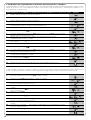
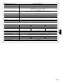
5 Testing and commissioning 14
5.1 Testing 14
5.2 Commissioning 15
6 Maintenance and Disposal 15
6.1 Maintenance 15
6.2 Disposal 15
7 Additional information 16
7.1 Programming keys 16
7.2 Programming 16
7.2.1 Level one functions (ON-OFF functions) 16
7.2.2 Level one programming (ON-OFF functions) 17
7.2.3 Level two functions (adjustable parameters) 18
7.2.4
Level two programming (adjustable parameters)
18
7.2.5 Level one programming examples
(ON-OFF functions) 19
7.2.6 Examples of Level 2 programming 20
7.3 Adding or Removing Devices 21
7.3.1 STOP Input 21
7.3.2 Photocells 22
7.3.3 Electric block 22
7.4 Special functions 23
7.4.1 “Always open” Function 23
7.4.2 “Move anyway” Function 23
7.5 Connection of other devices 23
7.6 Troubleshooting 23
7.7 Diagnostics and Signals 24
7.7.1 Signalling with flashing light and courtesy light 24
7.7.2 Signals on the control unit 24
7.8 Accessories 25
8 Technical characteristics 26
Instructions and Warnings for users of SPIN gearmotor 29

3
GB
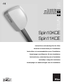
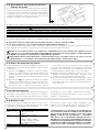
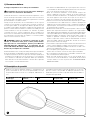
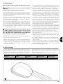
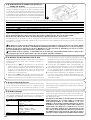
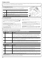
SPIN is a range of gearmotors designed for the automation of sec-
tional doors and, in combination with accessory SPA5 (supplied sep-
arately), protruding or non-protruding spring or counterweight over-
head doors.
SPIN operates with electric power. In the event of a power failure, the
gearmotor can be released in order to move the door manually.
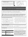
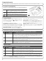
The products described in tables 1 belong to the SPIN range.
* see paragraph “4.5 radio receiver” for the types of transmitters that can used.
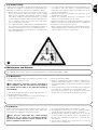
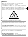
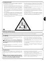
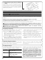
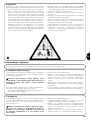
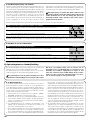
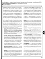
1) Warnings
Important instructions for installation safety
Incorrect installation may cause serious injury.
Carefully follow all installation instructions.
This manual contains important information regarding safety; before you
start installing the components, it is important that you read all the infor-
mation contained herein. Store this manual safely for future use.
In this manual when all data, warnings and other information related to
all products are stated, the range name “SPIN”. The description of indi-
vidual products can be found in chapter “2 Product description”
Considering the hazards that may exist during the installation and oper-
ation of SPIN, installation must be carried out in strict compliance with
current legislation, standards and regulations. This chapter provides
details of general warnings. Other, more specific warnings are detailed in
Chapters “3.1 Preliminary Checks” and “5 Testing and commissioning”.
According to the most recent European legislation, the
production of automatic doors or gates is governed by the
provisions listed in Directive 98/37/EC (Machine Directive)
and, more specifically, to provisions: EN 12445; EN 12453 and
EN 12635, which enable manufacturers to declare the pre-
sumed conformity of the product.
Please access “www.niceforyou.com” for further information, and guide-
lines for risk analysis and how to draw up the Technical Documentation.
• This manual has been especially written for use by qualified fitters.
Except for the enclosed specification “Instructions and Warnings for
Users of the SPIN gearmotor” which is to be removed by the installer,
none of the information provided in this manual can be considered as
being of interest to end users!
• Any use or operation of SPIN which is not explicitly provided for in
these instructions is not permitted. Improper use may cause damage
and personal injury.
• Risk analysis must be carried out before starting installation, to include
the list of essential safety requisites provided for in Enclosure I of the
Machine Directive, indicating the relative solutions employed. N.B. Risk
analysis is one of the documents included in the “Technical Documen-
tation” for this automation.
• Check whether additional devices are needed to complete the
automation with SPIN based on the specific application requirements
and dangers present. The following risks must be considered: impact,
crushing, shearing, dragging, etc. as well as other general dangers.
• Do not make modifications to any components unless such action is
specified in this manual. Operations of this type are likely to lead to
malfunctions. NICE disclaims any liability for damage resulting from
modified products.
• During installation and use, ensure that solid objects or liquids do not
penetrate inside the control unit or other open devices. If necessary,
please contact the NICE customer service department; the use of
SPIN in these conditions can be dangerous.
• The automation system must not be used until it has been commis-
sioned as described in chapter 5: “Testing and commissioning”.
• The packing materials of SPIN must be disposed of in compliance with
local regulations.
• If a fault occurs that cannot be solved using the information provided
in this manual, refer to the NICE customer service department.
• In the event that any automatic switches are tripped or fuses blown,
you must identify the fault and eliminate it before resetting the switch-
es or replacing fuses.
• Disconnect all the power supply circuits before accessing the terminals
inside the SPIN cover. If the disconnection device is not identifiable,
post the following sign on it: “WARNING: MAINTENANCE WORK IN
PROGRESS”.
!
!
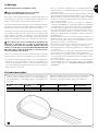
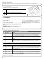
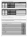
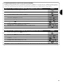
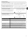
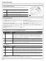
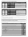
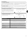
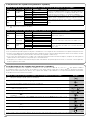
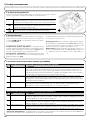
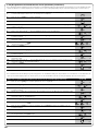
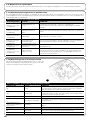
2) Product description
1
Model: Gearmotor Guide Radio receiver Radio Transmitter
SPIN10KCE SN6011 3x1m Incorporated FLO2R-S*
SPIN11KCE SN6011 3m Incorporated FLO2R-S*
Table 1: Description of the SPIN components

4
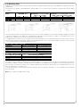
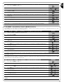
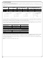
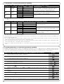
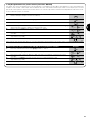
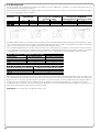
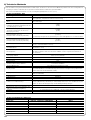
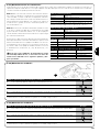
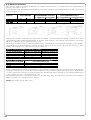
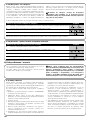
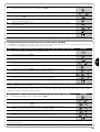
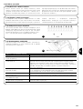
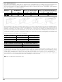
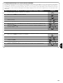
2.1) Operating limits
Chapter 8 “Technical Characteristics” provides the data needed to determine whether the products of the SPIN line are suitable for the intend-
ed application.
The structural characteristics of the SPIN products make it suitable for use on sectional and overhead doors within the limits shown in Tables
2, 3 and 4.
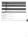
The measurements in table 2 are guideline only and can be used as a general estimate only. The effective suitability of SPIN for automating
a specific door depends on the degree of door leaf balancing, guide friction and other aspects, including occasional phenomena such as
wind pressure or the presence of ice, which could obstruct leaf movement.
To establish effective conditions, the force required to move the leaf throughout its stroke must be measured, to ensure that this value does
not exceed the “rated torque” specified in chapter “8 Technical specifications”; also, to calculate the number of cycles/hour and consecutive
cycles, the data in tables 3 and 4 must be taken into account.
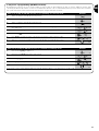
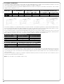
The height of the door enables a calculation of the maximum number of cycles per hour and consecutive cycles, while the force required to
move the door enables a calculation of the percentage of cycle reduction; for example, if the leaf height is 2.2 m this would enable 12 cycles
per hour and 6 consecutive cycles, but if a force of 250N is required, these would have to be reduced to 70%, resulting therefore in 8 cycles
per hour and around 4 consecutive cycles.
To avoid overheating, the control unit has a limiter that is based on the motor operation and duration of cycles, and trips when the maximum
limit is exceeded.
Note: 1Kg = 9.81N, for example, 500N = 51Kg
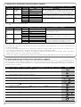
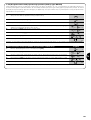
Model: SECTIONAL door OVERHEAD door, non-protruding OVERHEAD door, protruding (with accessory
(with accessory SPA5) SPA5) or with springs (without SPA5)
Height Width Height Width Height Width
SPIN10KCE 2.4m 3.7m 2.2m 3.5m 2.8m 3.5m
SPIN11KCE 2.4m 3.7m 2.2m 3.5m 2.8m 3.5m
Table 2: SPIN gearmotor operating limits
Leaf height Max. no. of cycles/hour
Max. no. of consecutive cycles
Max. 2 16 8
2÷2,5 12 6
2,5÷3 10 5
3÷3,5 8 4
Table 3: limits related to leaf height
Force required to move leaf N
Cycle reduction percentage
Max. 200 100%
200÷300 70%
300÷400 25
Table 4: limits in relation to force required to move door leaf

5
GB
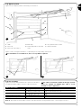
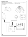
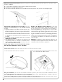
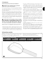
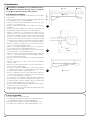
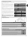
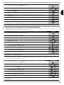
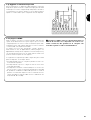
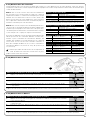
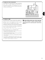
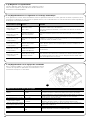
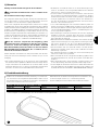
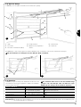
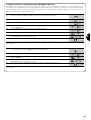
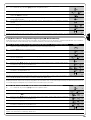
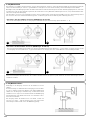
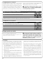
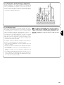
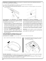
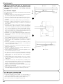
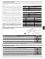
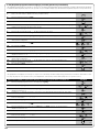
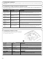
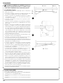
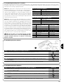
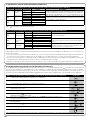
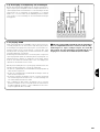
2.2) Typical system
Figure 2 shows a typical system for automating a sectional door.
2
1 SPIN
2 Photocells
3 Photocells on post (fig. 3)
4 Main edge
5 Flashing light with incorporated
aerial
6 Key-operated selector switch
7 Radio-transmitter
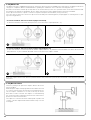
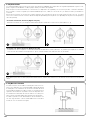
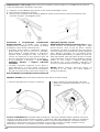
Figures 3 and 4 show typical installations of a protruding and non-protruding overhead door.
For installations on overhead doors, the accessory SPA5 is required.
!
3 4
5
6
C
B
A
2
2
4
B
B
D
7
1
3
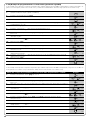
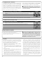
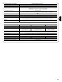
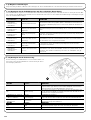
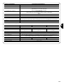
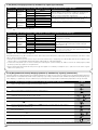
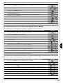
2.3) List of cables
Figure 3 shows the cables needed for the connection of the devices
in a typical installation; Table 5 shows the cable characteristics.
The cables used must be suitable for the type of instal-
lation. For example, an H03VV-F type cable is recom-
mended for indoor applications
!
Note 1: A single 4x0.5mm
2
cable can be used instead of two 2x0.5mm
2
cables.
Note 2: special devices which enable connection even when the leaf is moving must be used to connect edges to the door.
Connection Cable type Maximum length allowed
A: Flashing light with aerial N°1 cable 2x0,5mm
2
20m
N°1 RG58 type shielded cable 20m (recommended less than 5 m)
B: Photocells N°1 2x0,25mm
2
cable for TX 30m
N°1 4x0.25mm
2
cable for RX 30m
C: Key-operated selector switch N°2 2x0,5mm
2
cables (note 1) 50m
D: Primary sensitive edge N°1 2x0,5mm
2
cable (note 2) 30m
Table 5: list of cables
B

6
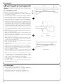
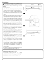
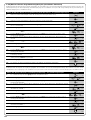
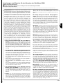
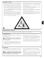
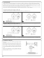
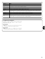
3.1) Preliminary checks
Before proceeding with the installation of SPIN you must:
• Verify and ensure after installation that no door parts obstruct pub-
lic roadways or pavements.
• Check that all the materials are in excellent condition, suitable for
use and that they conform to the standards currently in force.
• Make sure that the structure of the gate is suitable for automation.
• Make sure that the force and dimensions of the door fall within the
specified operating limits provided in chapter “2.1 Operating limits”.
• Check that the static friction (that is, the force required to start the
movement of the leaf) is less than half the “maximum torque”, and
that the dynamic friction (that is, the force required to keep the leaf
in movement) is less than half the "nominal torque”. Compare the
resulting values with those specified in Chapter 8 “Technical Char-
acteristics”. The manufacturer recommends a 50% margin on the
force, as unfavourable climatic conditions may cause an increase
in the friction.
• Make sure that there are no points of greater friction in the open-
ing or closing travel of the door.
• Make sure that the mechanical stops are sturdy enough, and that
there is no danger of door derailing.
• Make sure that the door is well balanced: it must not move by itself
when it is placed in any position.
• Make sure that the mounting positions of the various devices (pho-
tocells, keys, etc.) are protected from impacts and that the mount-
ing surfaces are sufficiently sturdy.
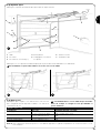
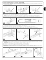
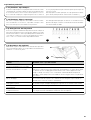
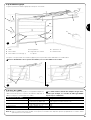
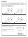
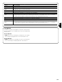
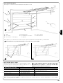
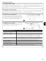
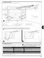
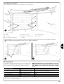
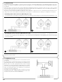
• Make sure that the minimum and maximum clearances specified
in fig. 5 and 6 are observed.
• Check and ensure that the manual release is fitted at a maximum
height of 1.8 m.
• Components must never be immersed in water or other liquids.
• Keep all components of SPIN away from heat sources and open
flames; these could damage the components and cause malfunc-
tions, fire or dangerous situations.
• If the door includes an access door, make sure that it does not
obstruct normal travel. Mount a suitable interlock system if neces-
sary.
• If the door to be automated is an overhead type, check the dis-
tance [E] in Figure 7, i.e. the minimum distance between the upper
side of the guide and the maximum point reached by the upper
edge of the door. Otherwise SPIN cannot be installed.
• Connect SPIN only to a power supply line equipped with safety
grounding system.
• The power supply line must be protected by suitable magneto-
thermal and differential switches.
7
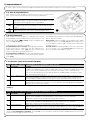
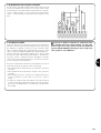
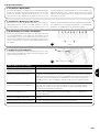
3.2) Fitting SPIN
Fixture of the SPIN gearmotor comprises 3 stages.
• Guide assembly (see paragraph 3.2.1 for guides supplied with
SPIN10KCE and paragraph 3.2.2 for guide SNA11)
• Mounting the gearmotor to the guide (see paragraph 3.2.3)
• Mounting the gearmotor to the ceiling (see paragraph 3.2.4)
The installation of SPIN must be carried out by qualified
personnel in compliance with current legislation, stan-
dards and regulations, and the directions provided in this
manual.
!
3) Installation
5
6
200mm
300mm
380mm
E 65÷300 mm
C 2970mm D 380mm
B 0÷400mm
A 40÷400mm
200mm

7
GB
B
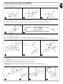
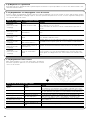
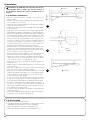
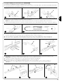
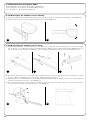
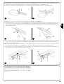
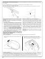
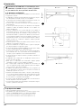
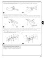
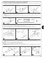
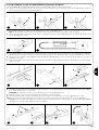
3.2.1) Assembly of guide supplied with SPIN10KCE
The guide that is supplied with SPIN10KCE must be assembled as follows:
1. Referring to figure 8, remove the belt tensioner device (8a); insert one end of the belt into the pulley (8b); reintroduce the belt tensioner
device into the guide (8c).
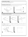
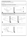
4. Position both ends of the belt into all of the shaped slots of the lower carriage (C). Secure the ends of the belt with the 2 screws (V4.2x9.5)
and 2 washers (R05), as in figure 11.
5. Fix the belt guide (D) to the upper carriage (E) with the V6x18 screw and related M6 nut, as in figure 12.
6. Insert the upper carriage (E)into the lower carriage (C) and place the entire carriage assembly inside the guide, as in figure 13.
7. With the aid of a hammer, assemble the three pieces of the guide engaging them into the connection brackets (F) with force, as in fig-
ures 14 and 15.
Important: the guides must slide into the brackets until they click into position.
8. Carefully position the belt into the guide, making sure that it is not twisted.
9. Fix the head (B) into the free end of the guide with force, as in figure 16.
10.Finally, tension the belt with the adjustment screw (H) of the belt tensioner device, as in figure 17.
Warning: the gearmotor could break if the belt is too taut and if it is too slack, it could cause unpleasant noise.
11 12 13
C
14 16 17
H
D
E
E
C
8A 8B 8C
10
A
B
9
A
A
2. Pass the same end of the belt through the head (B), as in figure 9.
Note: Make sure that the belt is correctly positioned: it must be with the teeth facing inwards, straight and without twists.
3. Turn the lower section of the carriage so that the grooves correspond with the two ends of the belt, as in figure 10.
F
15

8
3.2.2) SNA11 guide assembling
The guide SNA11 guide is already assembled. The only operation
required is tensioning the belt by means of the M8 nut (H), as shown
in figure 17, until it is sufficiently taut.
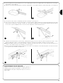
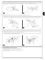
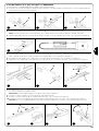
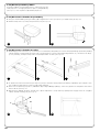
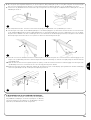
3.2.3) Mounting the gearmotor to the guide
1. Join the SPIN gearmotor with the guide head (B); then secure by means of the four V6.3x38, screws, as shown in figure 18.
2. The motor can be rotated in three different positions, as shown in figure 19.
18 19
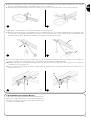
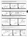
3.2.4) Fissaggio del motoriduttore al soffitto
1. On the basis of distances A and B in figure 5, trace the two fixing points of the front guide bracket at the centre of the door. On the basis
of the type of support surface, the front bracket can be fixed with rivets, plugs or screws (figures 20, 21). If distances A, and B (figure 5)
are sufficient, the bracket can be fixed directly onto the ceiling, as shown in figure 22.
2. After drilling the holes in the relative points, leaving the gearmotor on the ground, lift the guide from the front section and secure by means
of two screws, plugs or rivets, according to the installation surface.
3. Secure the brackets (I) by means of the M6x15 screws (L) and nuts M6 (M) selecting the hole most suited to ensure distance B, as shown
in figure 23.
4. Using a ladder, lift the gearmotor until the brackets are touching the ceiling. Trace the drilling points and then return the gearmotor to the
ground, as shown in figure 24.
20 21 22
23 24
L
M
I
B

9
GB
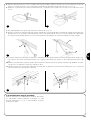
5. Drill at the outlined points and then, using a ladder, lift the gearmotor until the brackets are placed against the drilled holes and secure by
means of screws and plugs suited to the support surface, as shown in figure 25.
6. Ensure that the guide is perfectly horizontal, then cut off the excess section of the brackets with a saw, as shown in figure 26.
7. With the door closed, pull the cord to release carriage (E), as shown in figure 27.
8. Slide the carriage until the leaf connecting bracket (D) on the upper edge of the door is perfectly perpendicular to the guide (G). Then
secure the leaf connecting bracket (D) with rivets or screws, as shown in figure 28. Use screws or rivets suited to the leaf material, and
ensure that they are able to withstand the maximum force required for leaf opening and closing.
9. Loosen the screws of the two mechanical stops, then move the front mechanical stop (O) in front of the carriage, as shown in figure 29.
Push the carriage in the closing direction and, on reaching the position, tighten the screw (N) fully down.
10.Manually open the door to the required opening position, move the rear mechanical stop (Q) next to the carriage, as shown in figure 30
and tighten the screw (P) fully down.
11.Try to move the door manually. Ensure that the carriage slides easily without friction on the guide and that manual movement does not
require excessive force.
25 26
27 28
29 30
E
G
D
O
N
Q
P
3.3) Installation of the Various Devices
If other devices are needed, install them following the directions pro-
vided in the corresponding instructions. Check this in paragraph “3.5
Description of electrical connections” and the devices which can be
connected to the SPIN in Figure 2.

10
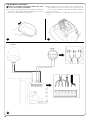
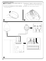
3.4) Electrical connections
Before you proceed to make any electrical connections
make sure that the power supply is disconnected.
1. Open the protection cover in order to access the electronic con-
trol unit of the SPIN. To do this, press the side and rotate as
shown in figure 31.
2. Insert all the connection cables towards the various devices
through the hole, leaving a length of 20÷30 cm longer than nec-
essary. See Table 5 for information regarding the type of cables
and Figure 2 for the connections.
3. Connect up the cables according to the diagram in Figure 33.
!
31 32
33
LUCYB
MOSE

11
GB
The manufacturers recommend you unhook the carriage and posi-
tion the leaf at approximately half travel before starting the checking
and start up phase of the automation. This will ensure the leaf is free
to move both during opening and closure.
4) Final checks and start up
4.1) Power Supply Connection
To power SPIN just insert the plug in a power outlet. If necessary, use
a commercial adapter if the plug on the SPIN unit does not corre-
spond to the socket available.
Never cut or remove the cable supplied with SPIN.
If not already available, the power socket for SPIN con-
nection must be made by qualified and experienced per-
sonnel in strict observance of current legislation, stan-
dards and regulations.
The power supply line must be protected from short cir-
cuits and ground leakage; a device must be provided to
enable the disconnection of the power supply during the
installation and maintenance of SPIN (the plug with outlet
are suitable for this purpose).
As soon as SPIN is energized, you should check the following:
1. Make sure that the “OK” LED flashes regularly, with about one
flash per second.
2. Check that the motor does not control the movement of the door
and that the courtesy light is off.
If the above conditions are not satisfied, you should immediately
switch off the power supply to the control unit and check the electri-
cal connections more carefully.
For more useful information about finding and analysing failures see
also chapter “7.6 Troubleshooting”
!
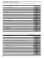
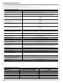
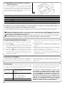
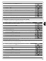
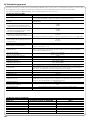
3.5) Description of the electrical connections
The following is a brief description of the electrical connections; for further information please read “7.3 Adding or Removing Devices” paragraph.
Terminals Function Description
1 – 2 Aerial connection input for the radio receiver aerial. The aerial is incorporated in LUCY B; alternatively
an external aerial can be used or leave a section of wire already present on the terminal, to serve
as an aerial.
3 – 4 Step-by-step input for devices which control movement. It is possible to connect “Normally Open” devices
up to this input.
5 – 6 Stop input for the devices which block or eventually stop the manoeuvre in progress. Contacts like
“Normally Closed”, “Normally Open” or constant resistance devices can be connected up
using special procedures on the input. Please refer to Paragraph “7.3.1 STOP Input” for
further information about STOP.
3 - 7 Photo Input for safety devices such as photocells. Cut-in during closure, reversing the manoeuvre.
“Normally closed “ type contacts can be connected. Further PHOTO information on the can be
seen in paragraph “7.3.2 PHOTO input”
6 – 8 Phototest Whenever a manoeuvre is begun, the relative safety devices are checked and only if everything is in
order will the manoeuvre start.
All this is only possible if a special configuration of the connections is used; in practice, the “TX”
photocell transmitters are powered separately from the “RX” receivers. Please refer to Paragraph
“7.3.2 PHOTO Input” for further information about the connection.
9 – 10 Flashing light a NICE “LUCY B” flashing light can be connected on this output with a car type 12 V 21 W lamp.
During the manoeuvre the unit flashes at intervals of 0.5 s.

12
4.2) Recognition of the door opening and closing
positions
The control unit must be made to recognize the opening and closing
positions of the door. In this phase, the door stroke from the closing
mechanical stop to the opening mechanical stop is detected. In
addition to position, the STOP input configuration is detected and
memorised in this phase as well as the existence or non-existence
of the PHOTO input “Phototest”.
1. Ensure that the drive belt is correctly tensioned and that the two mechanical stops are fully secured.
2. Engage the carriage.
3. Press keys []and [ Set ] and hold them down.
4. Release the keys when the manoeuvre starts (after approx. 3 s)
5. Wait for the control unit to complete the recognition stage: closing, opening and closing again of the door.
6. Push the [Step-by-Step] key to perform a complete opening manoeuvre.
7. Push the [Step-by-Step] key to close.
During these manoeuvres, the control unit memorises the force required for opening and closing.
If at the conclusion of the self-learning process the L2 and L3 flash, it means that an error has occurred; see paragraph 7.6 “Troubleshooting”.
It is important that these manoeuvres are not interrupted, e.g. by a STOP command.
If this occurs, the learning process described in point 1 must be repeated.
The recognition stage of the positions, and of the STOP and PHOTO input configuration can be repeated again at any time, even after the
installation (for example, if one of the mechanical stops is removed); just repeat the procedure starting from step
During the position search process, if the belt is not sufficiently tensioned, it may slip on the pinion. If this occurs,
press the [Stop] key to interrupt self-learning; tension the belt by tightening the M8 nut (D) as shown in figure 11, then
repeat self-learning from point 1.
Self-learning of the door opening and closing positions is only possible after the radio transmitter memorisation and
deletion time interval has elapsed (see paragraph 4.5 Radio receiver).
!
!
34
4.3) Checking door movements
On completion of the recognition of the opening and closing posi-
tions, it is advisable to carry out a number of manoeuvres in order to
check the door travels properly.
1. Press the [Step-by-Step] key to open the door. Check that
door opening occurs regularly, without any variations in speed;
the door must only slowdown and stop when it is between 30
and 20 cm from the opening mechanical stop. Then, at 2÷3 cm
from the mechanical opening stop the limit switch will trigger.
2. Press the [Step-by-Step] key to close the door. Check that door
closing occurs regularly, without any variations in speed; the door
must only slowdown and stop when it is between 30 and 20 cm
from the closing mechanical stop. A brief opening manoeuvre is
then performed to release belt tension.
3. During the manoeuvre, check that the flashing light (if any) flash-
es at a speed of 0.5 seconds on and 0.5 seconds off.
4. Open and close the gate several times to make sure that there
are no points of excessive friction and that there are no defects in
the assembly or adjustments.
5. Check that the fastening of the gearmotor, the guide and the
mechanical stops are solid, stable and suitably resistant, even if
the door accelerates or decelerates sharply.
4.4) Pre-set functions
The SPIN control unit has a number of programmable functions. These
functions are set to a configuration which should satisfy most automa-
tions. However, the functions can be altered at any time by means of a
special programming procedure. Please refer to paragraph “7.2 Pro-
gramming” for further information about this.
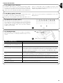
4.5) Radio receiver
A radio receiver is incorporated in the control unit of SPIN for remote
control, operating at a frequency of 433.92 MHz compatible with the
following types of transmitter:
Since the type of coding is different, the first transmitter that is intro-
duced also determines the type introduced afterwards. Up to 160
transmitters can be memorised.
Memorisation and deletion of transmitters must be per-
formed within the first 10 seconds after powering up the
unit. In this time interval, the control unit key [RADIO] is
used for radio memorisation and deletion functions. 10
seconds after the last flash of led L1 or after the last key
is pressed, the key is disabled and led L1 is dedicated to
programming. The courtesy light flashes once to indicate
the end of the interval in which radio memorisation func-
tions are enabled.
FLO FLO1 – FLO2 – FLO4
VERY VE
FLOR FLOR1 – FLOR2 – FLOR4
VERY VR
ERGO1 – ERGO4 – ERGO6
PLANO1 – PLANO4 – PLANO6
OPERA range transmitters
SMILO SM2 – SM4
Table 6: Transmitters

13
GB
1 “Step-by-step” command
2 “Partial opening” command
3 “Open” command
4 “Close” command
Table 8: commands available in Mode II
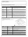
4.5.1) Memorization of Radio Transmitters
Each radio transmitter is recognised by the radio receiver by means of a “code” which is different from that of any other transmitter. A “mem-
orisation” phase must therefore be performed in order to allow the receiver to recognise each single transmitter. Transmitters can be mem-
orised in 2 modes:
Mode I: in this mode the function of the transmitter keys is fixed and
each key corresponds to the command in the control unit shown in
Table 7; a single memorisation phase is carried out for each trans-
mitter, during which all the transmitter keys are memorised. It does-
n’t matter which key is pressed and just one memory sector is occu-
pied. A transmitter can normally only control a single automation in
Mode I.
Mode II: In this mode, each transmitter key can be associated with
one of the 4 possible control unit commands shown in Table 8; only
one key is memorised for each stage, namely the one which was
pressed during memorisation. One memory section is occupied for
each key.
In Mode II, different keys on the same transmitter can be used in
order to give the same automation more than one command or to
control more than one automation. For example, in Table 9, only
automation “A”, is controlled, and the T3 and T4 keys are associat-
ed with the same command. Alternatively, three automations are
controlled in the example shown in Table 10, namely “A” (keys T1
and T2), “B” (key T3) and “C” (key T4).
Since the memorization procedures are timed (10s),
you must read the instructions in the following paragraphs
before you proceed with their execution.
!
T1 Key “Step-by-step” command
T2 Key “Partial opening” command
T3 Key “Open” command
T4 Key “Close” command
Table 7: Memorisation mode I
T1 Key “Open” command Automation A
T2 Key “Close” command Automation A
T3 Key “Partial opening” command Automation A
T4 Key “Partial opening” command Automation A
Table 9: 1st example of memorization in Mode II
T1 Key “Open” command Automation A
T2 Key “Close” command Automation A
T3 Key “Step-by-step” command Automation B
T4 Key “Step-by-step” command Automation C
Table 10: 2nd example of memorization in Mode II
Note: single-channel transmitters only have a T1 key, two channel
transmitters only have T1 and T2 keys.
1. Press the radio key on the control unit and hold it down (approx. 4 s)
4s
2. Release the key when the radio LED on the control unit lights up
3. Within 10s, press any key on the radio transmitter to be memorized and hold it down for at least 3s
3s
4. If the memorization procedure is successful, the radio LED on the control unit will flash 3 times.
x3
If there are other transmitters to memorise, repeat step 3 within another 10s seconds.
The memorisation phase finishes if no new codes are received for 10 seconds.
Table 11: to memorize a transmitter in mode I Example
4.5.2) Memorization Mode I
35
1. Press the radio key on the control unit as many times as the number corresponding to the desired
command, according to the table 8 1....4
2. Make sure that the radio LED on the control unit makes as many flashes as the number corresponding
to the desired command 1....4
3. Within 10s, press any key on the radio transmitter to be memorized and hold it down for at least 3s
3s
4. If the memorization procedure is successful, the LED on the receiver will flash 3 times.
x3
If there are other transmitters to memorise for the same type of command, repeat step 3 within another 10 seconds.
The memorisation phase finishes if no new codes are received for 10 seconds.
Table 12: to memorize the key of a transmitter in mode II Example
4.5.3) Memorization Mode II

14
1. Press the key on the new radio transmitter and hold it down for at least 5s, then release it.
5s
2. Press the key on the previously memorized transmitter slowly 3 times.
1s 1s 1s
3. Press the key on the new radio transmitter once slowly.
1s
At this point the new radio transmitter will be recognized by the receiver and will assume the characteristics of the previously memorized
one. If there are other transmitters to be memorized, repeat all the steps above for each new transmitter.
Table 13: for the “Remote” memorization of a transmitter Example
4.5.4) “Remote” memorization
A new radio transmitter can be memorized without directly operating
the keys on the receiver. You need to have a pre-memorized opera-
tional radio transmitter. The “new” radio transmitter will inherit the char-
acteristics of the old one, i.e. if the old radio transmitter was memo-
rized in Mode 1, the new one will also be memorized in Mode 1. In this
case, during the memorization stage you can press any key on the
transmitters. If, on the other hand, the old transmitter was memorized
in Mode II, the new one will also be memorized in Mode II: you must
press the key on the old transmitter which corresponds to the
desired command, and the key on the new transmitter to which you
wish to associate that command.
Programming via radio may be done on all the receivers
within the range of the transmitter; therefore, only the one
involved in the operation should be kept switched on.
!
Holding the two transmitters, position yourself within the operating range of the automation and perform the following operations:
1. Press the radio key on the control unit and hold it down
2.
Wait until the radio LED lights up, then wait until it goes off, then wait until it has flashed 3 times
x3
3. Release the radio key precisely upon the third flash.
4. If the procedure is successful, after a few moments the LED will flash 5 times.
x5
Table 14: to delete all the radio transmitters Example
4.5.5) Deleting the Radio Transmitters
This is the most important stage in the automation system installa-
tion procedure in order to ensure the maximum safety levels.
Testing can also be adopted as a method of periodically checking
that all the various devices in the system are functioning correctly.
Testing of the entire system must be performed by qual-
ified and experienced personnel who must establish which
tests to conduct on the basis of the risks involved, and ver-
ify the compliance of the system with applicable regula-
tions, legislation and standards, in particular with all the
provisions of EN standard 12445 which establishes the test
methods for automation systems for gates and doors.
!
5) Testing and commissioning
5.1) Testing
Each component of the system, e.g. safety edges, photocells, emer-
gency stop, etc. requires a specific testing phase. We therefore rec-
ommend observing the procedures shown in the relative instruction
manuals.
To test SPIN proceed as follows:
1. Make sure that the provisions contained in chapter 1 «WARN-
INGS» have been carefully observed.
2. Release the door by pulling the release cord downwards. Check
that the door can be manually manoeuvred with a force no
greater than 225N.
3. Engage the carriage again.
4. Using the selector switch or the radio transmitter, test the open-
ing and closing of the door and make sure that the door moves
in the intended direction.
5. The test should be carried out a number of times to make sure
that the gate moves smoothly, that there are no points of exces-
sive friction and that there are no defects in the assembly or
adjustments.
6. Check the proper operation of all the safety devices, one by one
(photocells, sensitive edges, etc.).
In particular, each time a device is activated the “OK” LED on the
control unit flashes 2 times quickly, confirming that the control unit
recognizes the event.
7. To check the photocells and make sure that there is no interfer-
ence with other devices, pass a 5 cm diameter, 30 cm long cylin-
der on the optical axis, first near TX, then near RX and finally at
the mid-point between them and make sure that in all these cas-
es the device is triggered, switching from the active to the alarm
status and vice-versa; finally, that it causes the intended action in
the control unit; for example that it causes the reversal of the
movement during the closing manoeuvre.
8. If the dangerous situations caused by the movement of the door
have been safeguarded by limiting the force impact, the user
must measure the impact force according to EN Standard 12445.
If the adjustment of the “speed” and control of the “motor force”
are used to assist the system for the reduction of the impact
force, try to find the adjustment that gives the best results

15
GB
5.2) Commissioning
Commissioning can take place only after all testing phases have been
terminated successfully. It is not permissible to execute partial com-
missioning or to enable use of the system in makeshift conditions.
1. Prepare and store for at least 10 years the technical documenta-
tion for the automation, which must include at least: assembly
drawing of the automation, wiring diagram, analysis of hazards
and solutions adopted, manufacturer’s declaration of conformity
of all the devices installed (for SPIN use the annexed CE declara-
tion of conformity); copy of the instruction manual and mainte-
nance schedule of the automation.
2. Post a permanent label or sign near the door detailing the opera-
tions for the release and manual manoeuvre (refer to the figures in
“Instructions and warnings for users of the SPIN gearmotor”).
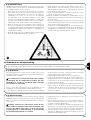
3. Post a permanent label or sign near the door containing this pic-
ture (min. height 60 mm).
4. Post a label on the door providing at least the following data: type
of automation, name and address of manufacturer (person
responsible for the “commissioning”), serial number, year of man-
ufacture and “CE” marking.
5. Prepare the declaration of conformity of the automation system
and deliver it to the owner.
6. Prepare the “Installation instructions and warnings” of the
automation system and deliver it to the owner.
7. Prepare the maintenance schedule of the automation system and
deliver it to the owner; it must provide all directions regarding the
maintenance of all the automation devices.
Before commissioning the automation system inform the owner in
writing regarding dangers and hazards that are still existing (e.g.
in the “Installation instructions and warnings”).
36
This chapter provides information about how to draw up a maintenance schedule, and the disposal of SPIN.
6) Maintenance and Disposal
6.1) Maintenance
The automation must be subjected to maintenance work on a regu-
lar basis, in order to guarantee it lasts.
The maintenance operations must be performed in
strict compliance with the safety directions provided in
this manual and according to the applicable legislation
and standards.
If other devices are present, follow the directions provided in the cor-
responding maintenance schedule.
1. SPIN requires scheduled maintenance work every 6 months or
3,000 manoeuvres after previous maintenance.
2. Disconnect the power supply
3. Check for any deterioration of the components which form the
automation, paying special attention to erosion or oxidation of the
structural parts. Replace any parts which are below the required
standard.
4. Check the wear and tear on the moving parts: belt, carriage, pin-
ions and the door components; if necessary replace them.
Connect the electric power sources up again, and carry out all
the tests and checks described in paragraph 5.1 “Testing”.
!
6.2) Disposal
SPIN is constructed of various types of materials, some of which can
be recycled: steel, aluminium, plastic, electric cables; while others
must be disposed of (batteries and electronic boards).
Some electronic components may contain polluting
substances; do not pollute the environment. Enquire
about the recycling or disposal systems available in com-
pliance regulations locally in force.
1. Disconnect the power supply of the automation system.
2. Disassemble all the devices and accessories, following in reverse
order the procedures described in chapter 3 “Installation”.
3. Wherever possible, separate any parts which can or must be
recycled or disposed of in different ways, e.g. metal parts must
be disposed of separately from plastic ones, as must the elec-
tronic cards etc.
4. Sort the various materials and consign them to local licensed
firms for recovery and disposal.
!

16
This chapter deals with the options for programming, personalisation, diagnostics and troubleshooting for the SPIN gearmotor.
7) Further information
RADIO Within the first 10 seconds after power-up, perform the “RADIO” function to
enable memorisation and deletion of the radio transmitters used with SPIN.
After this time interval, the key is no longer used.
Stop The STOP key stops the manoeuvre; if pressed for more than 5 seconds,
SET it enables entry to programming mode as described below.
SS The SS key enables door opening and closing commands; otherwise this key
can be used to scroll up through the programming steps.
7.1) Programming keys
The SPIN control unit is fitted with 3 keys which can be used both for the control of
the unit during testing and the programming procedure:
7.2) Programming
The SPIN control unit is equipped with a number of programmable
functions; function settings are entered by means of the 2 keys on
the control unit: []and [Set] and are displayed by means of 3
leds: L1, L2, L3.
There are two types of programming:
Programming on power-up: This type of programming can be
performed only immediately after switching on SPIN. Press and hold
[Set] during power-up of the control unit to activate this program-
ming mode.
Standard programming: This programming mode can be used at
any time and is activated by pressing and holding [Set].
For both modes, the programming and programmable functions
available are divided into 2 levels:
Level 1: functions settable in ON-OFF mode (enabled or disabled);
in this case leds L1, L2, and L3 indicate a function, if lit the function
is enabled, if off the function is disabled; see Tables 15 and 15a.
Level 2: parameters settable on a scale of values (from 1 to 3); in
this case each led L1, L2, L3 indicates a set value from the possi-
ble 3; see Tables 17 and 17a.
37
N° Description Example
L1 Variable Sensitivity This function enables the user to enable or disable sensitivity with which obstacles are detected.
The factory setting of sensitivity is variable (led L1 off): Greater sensitivity in the case of low motor force,
and less sensitivity where the motor force increases. All with the aim of ensuring optimal detection
precision. Variable sensitivity can be disabled, and 3 “fixed” levels of motor force remain (led L1 lit).
L2 Phototest/Electric block This function enables the user to enable output 8 of the terminal board for operation with Phototest or
with an Electric block. The factory setting of output 8 is with the “phototest” function enabled (led L2 off).
Alternatively the output can be programmed on the SPIN control unit for control of an electric block
(led L2 lit).
L3 Partial open This function enables the selection of a long or short partial opening interval. The factory setting for
partial open is long (approx. 1 m, led L3 lit). Alternatively partial open can be set to short (approx. 15cm,
led L3 off).
At the end of the “Programming on power-up” procedure, leds L1, L2 and L3 indicate the status of the functions in “Standard pro-
gramming” mode.
Table 15: List of programmable functions in “Programming on power-up” mode
7.2.1) Level 1 functions (ON-OFF functions)
N° Description Example
L1 Closing speed This function enables the selection of the motor speed during the closing manoeuvre, from 2 levels:
“high” and “low”. The factory setting is “high” (led L1 lit). Alternatively the function can be disabled to set
the “low” speed (led L1 off).
L2 Opening speed This function enables the selection of the motor speed during the opening manoeuvre, from 2 levels:
“high” and “low”. The factory setting is “high” (led L2 lit). Alternatively the function can be disabled to set
the “low” speed (led L2 off).
L3 Automatic closure This function enables automatic closure of the door after a programmed pause; the default Pause Time
is set at 30 seconds but may be modified to 15 or 60 seconds. The factory setting is “semiautomatic”
as Automatic closure is disabled (led L3 off).
During normal operation of SPIN, leds L1, L2 and L3 are lit or off depending on the status of the associated function in Standard pro-
gramming mode, for example L3 is lit if the function “Automatic closure” is enabled. L1 also displays the status of the “radio” function in
the first 10 seconds after power-up.
Table 15a: List of programmable functions in “Standard programming” mode

17
GB
7.2.2) Level 1 programming (ON-OFF functions)
By default level 1 functions are set as shown in tables 15 and 15a, but can be modified at any time as shown in tables 16 and 16a. Take
care during modification procedures, as there is a maximum time interval of 10 seconds between pressing one key and another; otherwise
the system exits the procedure automatically memorising the changes made up to that time.
1. Switch off SPIN (for example by removing fuse F1)
2. Press and hold [Set]
3. Switch on SPIN (for example by inserting fuse F1)
4. Wait for the flashing signal indicating control unit start-up and keep [Set] pressed until L1 starts to
flash (approx. 6s) L1 6s
5. Release the key [Set] when led L1 starts to flash
L1
6. Press key []to move the flashing led to the led associated with the function to be modified
7. Press [Set] to change the status of the function (short flash = OFF; long flash = ON)
8. Wait 10s to exit the programming mode automatically after the maximum time interval.
10s
Note: points 6 and 7 can be repeated during the same programming phase to set other functions to ON or OFF.
Table 16: To modify the ON-OFF functions in “programming on power-up” mode Example
SET
SET
SET
SET
1. Press and hold [Set] for approx. 3s
3s
2. Release the key [Set] when led L1 starts to flash
L1
3. Press key []to move the flashing led to the led associated with the function to be modified
4. Press [Set] to change the status of the function (short flash = OFF; long flash = ON)
5. Wait 10s to exit the programming mode automatically after the maximum time interval.
10s
Note: points 3 and 4 can be repeated during the same programming phase to set other functions to ON or OFF
Table 16a: To modify the ON-OFF functions in “standard programming” mode Example
SET
SET
SET

18
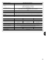
Sensitivity
variable
Belt recovery
Closing
slowdown
High
Medium
Low
No recovery
Minimum recovery
Maximum recovery
Short
Medium
Long
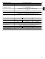
7.2.3) LEVEL 2 functions (adjustable parameters)
Table 17: List of level 2 programmable functions in “Programming on power-up” mode
Input leds Parameter Led (level) Value Description
When variable sensitivity is enabled, it can be set to three dif-
ferent activation thresholds. “High” variable sensitivity is most
suited to small size correctly balanced doors.
Sets the belt recovery value. After complete closure of the
door, a very brief opening manoeuvre is activated, settable
with this parameter.
Sets the slowdown time interval during the closing manoeuvre.
Note: “ ” Represents factory settings.
L1
L2
L3
L1
L2
L3
L1
L2
L3
L1
L2
L3
7.2.4) Level 2 programming (adjustable parameters)
By default the settable parameters are set as shown in Tables 17 and 17a with: “ “ but can be modified at any time as shown in Tables
18 and 18a. Take care during modification procedures, as there is a maximum time interval of 10 seconds between pressing one key and
another; otherwise the system exits the procedure automatically memorising the changes made up to that time.
1. Switch off SPIN (for example by removing fuse F1)
2. Press and hold [Set]
3. Switch on SPIN (for example by inserting fuse F1)
4. Wait for the flashing signal indicating control unit start-up and keep [Set] pressed until L1 starts to flash
(approx. 6s) L1 6s
5. Release the key [Set] when led L1 starts to flash
L1
6. Press key []to move the flashing led to the “input led” associated with the parameter to be
modified
7. Press and hold [Set] during steps 5 and 6
8. Wait approx. 3s after which the led associated with the current level of the parameter to be modified
will light up 3s
9. Press key []to move the led associated with the parameter value.
10. Release [Set]
11. Wait 10s to exit the programming mode automatically after the maximum time interval.
10s
Note: Points 6 to 10 can be repeated during the same programming phase to modify other parameters
Table 18: To modify the adjustable parameters in “programming on power-up” mode Example
SET
SET
SET
SET
Motor force
SS function.
Pause Time
Low
Medium
High
Open, Stop, Close, Open
Open, Stop, Close, Stop
Apartment block
15 seconds
30 seconds
60 seconds
Table 17a: List of level 2 programmable functions in “Standard programming” mode
Input leds Parameter Led (level) Value Description
Sets the maximum force generated by the motor to
move the door.
Adjusts the sequence of commands associated with
the SS input or the 1st radio command (see tables 7
and 8).
Adjusts the pause time, i.e. time before automatic re-
closure. Is effective only if automatic closure is enabled
Note: “ ” Represents factory settings.
All parameters can be adjusted as required without any contraindications, only the “Motor force” setting may require special attention:
• Use of high force values are not recommended to compensate for the fact that the leaf has anomalous points of friction; excessive force
may impair the safety system and damage the leaf.
• If the “Motor force control” is used in support of the system for impact force reduction, after each adjustment the force measurement pro-
cedure must be performed, as envisaged by standard EN 12445.
• Wear and atmospheric conditions influence movement of the gate; force settings should be checked periodically.
L1
L2
L3
L1
L2
L3
L1
L2
L3
L1
L2
L3
SET

19
GB
1. Press and hold [Set] for approx. 3s
3s
2. Release the key [Set] when led L1 starts to flash
L1
3. Press key []to move the flashing led to the “input led” associated with the parameter to be
modified
4. Press and hold [Set] during steps 5 and 6
5. Wait approx. 3s after which the led associated with the current level of the parameter to be modified
will light up
6. Press key []to move the led associated with the parameter value.
7. Release [Set]
8. Wait 10s to exit the programming mode automatically after the maximum time interval.
10s
Note: Points 3 to 7 can be repeated during the same programming phase to modify other parameters
Table 18a: To modify the adjustable parameters in “standard programming” mode Example
SET
SET
SET
SET
7.2.5) LEVEL 1 programming examples (ON-OFF functions)
This example shows the sequence of operations required to change the factory setting of the functions to deactivate the function of “Vari-
able Sensitivity” (L1) and activate “Short Partial Open” (L3).
1. Switch off SPIN (for example by removing fuse F1)
2. Press and hold [Set]
L1
3. Switch on SPIN (for example by inserting fuse F1)
4. Wait for the flashing signal indicating control unit start-up and keep [Set] pressed until L1 starts to flash
(approx. 6s) L1 6s
5. Release [Set]
6. Press [Set] once to change the status of the function associated with L1 (Variable Sensitivity) led L1
now emits long flashes L1
7. Press []twice to move the flashing led onto led L3
L3
8. Press [Set] once to change the status of the function associated with L3 (Partial open) led L3 now
emits long flashes L3
9. Wait 10s to exit the programming mode automatically after the maximum time interval
10s
On standby to exit programming mode, leds L1 and L3 must remain lit to indicate that the functions “Variable Sensitivity disabled” and “Short
Partial Open” are active.
Table 19: Example of LEVEL 1 programming in “Programming on power-up” mode Example
SET
SET
SET
This example shows the sequence of operations required to change the factory setting of the functions to activate the functions of “High
opening speed” (L2) and “Automatic Closure” (L3).
1. Press and hold [Set] for approx. 3s
3s
2. Release the key [Set] when led L1 starts to flash
L1
3. Press the key [] once to move the flashing led onto led L2
L2
4. Press [Set] once to change the status of the function associated with L2 (Opening speed) led L2 now
emits long flashes L2
5. Press the key []once to move the flashing led onto led L3
L3
6. Press [Set] once to change the status of the function associated with L3 (Automatic closure) led L3
now emits long flashes L3
7. Wait 10s to exit the programming mode automatically after the maximum time interval
10s
At the end of these operations leds L2 and L3 must remain lit to indicate that the functions “High opening speed” and “Automatic closure” are
enabled.
Table 19a: Example of LEVEL 1 programming in “Standard programming” mode Example
SET
SET
SET
SET
SET
SET

20
7.2.6) Examples of LEVEL 2 programming
This example shows the sequence of operations required to change the factory setting of the parameters and set the functions of “Belt
Recovery” to no recovery (input on L2 and level on L1) and set “Closing slowdown” to long (input on L3 and level on L3).
1. Switch off SPIN (for example by removing fuse F1)
2. Press and hold [Set]
3. Switch on SPIN (for example by inserting fuse F1)
4. Wait for the flashing signal indicating control unit start-up and keep [Set] pressed until L1 starts to flash
(approx. 6s) L1 6s
5. Release [Set]
6. Press the key []once to move the flashing led onto led L2
L2
7. Press and hold [Set] during steps 8 and 9
8. Wait approx. 3s until led L2 lights up, indicating the current level of “Belt recovery”
L2 3s
9. Press the key []once to move the illuminated led onto L1, to eliminate “Belt recovery”
L1
10. Release [Set]
11. Press the key []once to move the flashing led onto led L3
L3
12. Press and hold [Set] during steps 13 and 14
13. Wait approx. 3s until led L2 lights up, indicating the current level of “Closing slowdown”.
L2 3s
14. Press the key []once to move the illuminated led onto L3, indicating the new value of
“Closing slowdown”. L3
15. Release [Set]
16. Wait 10s to exit the programming mode automatically after the maximum time interval.
10s
Table 20: Example of LEVEL 2 programming in “Programming on power-up” mode Example
SET
SET
SET
SET
SET
SET
SET
This example shows the sequence of operations required to change the factory setting of the parameters and set the functions of “Motor
Force” to high (input on L1 and level on L3) and increase the “Pause Time” to 60s (input on L3 and level on L3).
1. Press and hold [Set] for approx. 3s
3s
2. Release the key [Set] when led L1 starts to flash
L1
3. Press and hold [Set] during steps 4 and 5
4. Wait approx. 3s until led L2 lights up, indicating the current level of “Motor Force”
L2 3s
5. Press the key []once to move the illuminated led onto L3, indicating the new value of “Motor Force”
L3
6. Release [Set]
7. Press []twice to move the flashing led onto led L3
L3
8. Press and hold [Set] during steps 9 and 10
9. Wait approx. 3s until led L2 lights up, indicating the current level of “Pause Time”.
L2 3s
10. Press the key []once to move the illuminated led onto L3, indicating the new value of “Pause Time”.
L3
11. Release [Set]
12. Wait 10s to exit the programming mode automatically after the maximum time interval.
10s
Table 20a: Example of LEVEL 2 programming in “Standard programming” mode Example
SET
SET
SET
SET
SET
SET
Page is loading ...
Page is loading ...
Page is loading ...
Page is loading ...
Page is loading ...
Page is loading ...
Page is loading ...
Page is loading ...
Page is loading ...
Page is loading ...
Page is loading ...
Page is loading ...
Page is loading ...
Page is loading ...
Page is loading ...
Page is loading ...
Page is loading ...
Page is loading ...
Page is loading ...
Page is loading ...
Page is loading ...
Page is loading ...
Page is loading ...
Page is loading ...
Page is loading ...
Page is loading ...
Page is loading ...
Page is loading ...
Page is loading ...
Page is loading ...
Page is loading ...
Page is loading ...
Page is loading ...
Page is loading ...
Page is loading ...
Page is loading ...
Page is loading ...
Page is loading ...
Page is loading ...
Page is loading ...
Page is loading ...
Page is loading ...
Page is loading ...
Page is loading ...
Page is loading ...
Page is loading ...
Page is loading ...
Page is loading ...
Page is loading ...
Page is loading ...
Page is loading ...
Page is loading ...
Page is loading ...
Page is loading ...
Page is loading ...
Page is loading ...
Page is loading ...
Page is loading ...
Page is loading ...
Page is loading ...
Page is loading ...
Page is loading ...
Page is loading ...
Page is loading ...
Page is loading ...
Page is loading ...
Page is loading ...
Page is loading ...
Page is loading ...
Page is loading ...
Page is loading ...
Page is loading ...
Page is loading ...
Page is loading ...
Page is loading ...
Page is loading ...
Page is loading ...
Page is loading ...
Page is loading ...
Page is loading ...
Page is loading ...
Page is loading ...
Page is loading ...
Page is loading ...
Page is loading ...
Page is loading ...
Page is loading ...
Page is loading ...
Page is loading ...
Page is loading ...
Page is loading ...
Page is loading ...
Page is loading ...
Page is loading ...
Page is loading ...
Page is loading ...
Page is loading ...
Page is loading ...
Page is loading ...
Page is loading ...
Page is loading ...
Page is loading ...
Page is loading ...
Page is loading ...
Page is loading ...
Page is loading ...
Page is loading ...
Page is loading ...
Page is loading ...
Page is loading ...
Page is loading ...
Page is loading ...
Page is loading ...
Page is loading ...
Page is loading ...
Page is loading ...
Page is loading ...
Page is loading ...
Page is loading ...
Page is loading ...
Page is loading ...
Page is loading ...
Page is loading ...
Page is loading ...
Page is loading ...
Page is loading ...
Page is loading ...
Page is loading ...
Page is loading ...
Page is loading ...
Page is loading ...
Page is loading ...
Page is loading ...
Page is loading ...
Page is loading ...
Page is loading ...
Page is loading ...
Page is loading ...
Page is loading ...
Page is loading ...
Page is loading ...
Page is loading ...
Page is loading ...
Page is loading ...
Page is loading ...
Page is loading ...
Page is loading ...
Page is loading ...
Page is loading ...
Page is loading ...
Page is loading ...
Page is loading ...
Page is loading ...
Page is loading ...
Page is loading ...
Page is loading ...
Page is loading ...
Page is loading ...
Page is loading ...
Page is loading ...
Page is loading ...
Page is loading ...
Page is loading ...
Page is loading ...
Page is loading ...
Page is loading ...
Page is loading ...
Page is loading ...
Page is loading ...
Page is loading ...
Page is loading ...
Page is loading ...
Page is loading ...
Page is loading ...
Page is loading ...
Page is loading ...
Page is loading ...
Page is loading ...
Page is loading ...
Page is loading ...
Page is loading ...
Page is loading ...
Page is loading ...
Page is loading ...
Page is loading ...
Page is loading ...
Page is loading ...
Page is loading ...
Page is loading ...
Page is loading ...
Page is loading ...
Page is loading ...
-
 1
1
-
 2
2
-
 3
3
-
 4
4
-
 5
5
-
 6
6
-
 7
7
-
 8
8
-
 9
9
-
 10
10
-
 11
11
-
 12
12
-
 13
13
-
 14
14
-
 15
15
-
 16
16
-
 17
17
-
 18
18
-
 19
19
-
 20
20
-
 21
21
-
 22
22
-
 23
23
-
 24
24
-
 25
25
-
 26
26
-
 27
27
-
 28
28
-
 29
29
-
 30
30
-
 31
31
-
 32
32
-
 33
33
-
 34
34
-
 35
35
-
 36
36
-
 37
37
-
 38
38
-
 39
39
-
 40
40
-
 41
41
-
 42
42
-
 43
43
-
 44
44
-
 45
45
-
 46
46
-
 47
47
-
 48
48
-
 49
49
-
 50
50
-
 51
51
-
 52
52
-
 53
53
-
 54
54
-
 55
55
-
 56
56
-
 57
57
-
 58
58
-
 59
59
-
 60
60
-
 61
61
-
 62
62
-
 63
63
-
 64
64
-
 65
65
-
 66
66
-
 67
67
-
 68
68
-
 69
69
-
 70
70
-
 71
71
-
 72
72
-
 73
73
-
 74
74
-
 75
75
-
 76
76
-
 77
77
-
 78
78
-
 79
79
-
 80
80
-
 81
81
-
 82
82
-
 83
83
-
 84
84
-
 85
85
-
 86
86
-
 87
87
-
 88
88
-
 89
89
-
 90
90
-
 91
91
-
 92
92
-
 93
93
-
 94
94
-
 95
95
-
 96
96
-
 97
97
-
 98
98
-
 99
99
-
 100
100
-
 101
101
-
 102
102
-
 103
103
-
 104
104
-
 105
105
-
 106
106
-
 107
107
-
 108
108
-
 109
109
-
 110
110
-
 111
111
-
 112
112
-
 113
113
-
 114
114
-
 115
115
-
 116
116
-
 117
117
-
 118
118
-
 119
119
-
 120
120
-
 121
121
-
 122
122
-
 123
123
-
 124
124
-
 125
125
-
 126
126
-
 127
127
-
 128
128
-
 129
129
-
 130
130
-
 131
131
-
 132
132
-
 133
133
-
 134
134
-
 135
135
-
 136
136
-
 137
137
-
 138
138
-
 139
139
-
 140
140
-
 141
141
-
 142
142
-
 143
143
-
 144
144
-
 145
145
-
 146
146
-
 147
147
-
 148
148
-
 149
149
-
 150
150
-
 151
151
-
 152
152
-
 153
153
-
 154
154
-
 155
155
-
 156
156
-
 157
157
-
 158
158
-
 159
159
-
 160
160
-
 161
161
-
 162
162
-
 163
163
-
 164
164
-
 165
165
-
 166
166
-
 167
167
-
 168
168
-
 169
169
-
 170
170
-
 171
171
-
 172
172
-
 173
173
-
 174
174
-
 175
175
-
 176
176
-
 177
177
-
 178
178
-
 179
179
-
 180
180
-
 181
181
-
 182
182
-
 183
183
-
 184
184
-
 185
185
-
 186
186
-
 187
187
-
 188
188
-
 189
189
-
 190
190
-
 191
191
-
 192
192
-
 193
193
-
 194
194
-
 195
195
-
 196
196
-
 197
197
-
 198
198
-
 199
199
-
 200
200
-
 201
201
-
 202
202
-
 203
203
-
 204
204
-
 205
205
-
 206
206
-
 207
207
-
 208
208
-
 209
209
-
 210
210
-
 211
211
-
 212
212


Nice Spin11KCE Owner's manual
- Type
- Owner's manual
- This manual is also suitable for
Ask a question and I''ll find the answer in the document
Finding information in a document is now easier with AI
in other languages
- italiano: Nice Spin11KCE Manuale del proprietario
- français: Nice Spin11KCE Le manuel du propriétaire
- español: Nice Spin11KCE El manual del propietario
- Deutsch: Nice Spin11KCE Bedienungsanleitung
- Nederlands: Nice Spin11KCE de handleiding
- polski: Nice Spin11KCE Instrukcja obsługi
Related papers
-
Nice ROAD 400 Instructions And Warnings For Installation And Use
-
 NiceHome Maestro 200 Owner's manual
-
-
Nice HYKE and HYKE Hi-speed series Owner's manual
-
-
-
-
-
-
Nice ROBO RO1040 Owner's manual

Other documents
-
Nice Automation Spin and Spinbus Owner's manual
-
 King gates OVO User manual
-
 Mhouse GD1, GD5 and GD10 Owner's manual
-
 Mhouse GD0 Owner's manual
-
 Mhouse WK2 Owner's manual
-
 Mhouse WG2 Owner's manual
-
Mhouse WG10 & WG20 Owner's manual
-
 Mhouse GDS Owner's manual
-
 Mhouse SL1S and SL10S Owner's manual
-
 Mhouse WU2S Owner's manual


