Page is loading ...

Division of BETA UTENSILI spa Via Volta. 18 - 20050 SOVICO (MB) ITALY Tel. +39.039.20771-Fax + 39.039.2010742
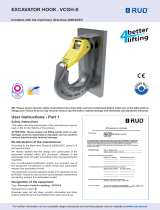
INSTRUCTIONS
according to 2006/42/EC Machine Directive
Translation of original instructions
Item 8090
Co n n e c ting li nk
ACCESSORIES
FOR WIRE ROPE ROBUR
Industrial Zone – C.da S. Nicola
67039 SULMONA (L’AQUILA)
Tel. +39.0864.2501.1 – Fax +39.0864.253132
www.roburitaly.com
All measurements are expressed in mm.
1. General notices
With reference to the contents of these instructions for use, the
manufacturer refuses any responsibility in the event of:
The use of accessories in a manner contrary to national
safety and accident prevention legislation.
Incorrect choice or predisposition of the lifting apparatus
with which they shall be connected.
Failure to observe correctly these instructions for use.
Unauthorised modifications to the accessories.
Improper use or lack of ordinary maintenance
Use combined with non-conforming accessories
2. Criteria of choice and life of accessory
The connecting link must be used as a lifting accessory
component assembled in a sling chain conforming to EN
818-4.
Static proof coefficient (MPF) equals to 2,5 times lifting
capacity.
The parameters which must be carefully considered when
choosing the accessory are as follows:
A. Maximum work load (WLL or lifting capacity):
The maximum work load (WLL) is a function of the grade and
configuration which for sling chains with single arm
corresponds to the values of the table below:
Maximum work load
Diameter of grade 8 chain (mm)
WLL
6 7 8 10 13 16 20 22 26 32
t
1,12 1,5 2 3,15 5,3 8 12.5 15 21,2 31,5
Ø
CHAIN
WLL
kg
A B ØC
D
E LU
g
CODE
6 1120
7 11 13 16
16.5
43 87
080900011
7-8 2000
9.5
13.5
18 20
23 55 164
080900020
10 3150
12
17 22 25
28 67 308
080900032
13 5300
17
22 26 30
34 84 665
080900053
16 8000
22
28 32 36
41 104
1130
080900080
R/SP-E/8090/02
Data 14/01/2011
Doc.n° IPU-181 Rev.2

Division of BETA UTENSILI spa Via Volta. 18 - 20050 SOVICO (MB) ITALY Tel. +39.039.20771-Fax + 39.039.2010742
B. The grade:
The grade must be the same as that of the chain used to form
the sling chain.
C. Temperature of use:
The temperature of use shall be included in the range
indicated in the table below, bearing in mind the variation of
the lifting capacity on the basis of the temperature
Load expressed as a percentage
of the maximum work load
Temperature, t, °C
Grade
-40 < t ≤ 200 200 < t ≤ 300 300 < t ≤ 400
8 100 90 75
D. Life span and frequency of use:
The life span of this accessory is anticipated as being for
20,000 operational cycles at full load.
3. Marking
Marking and/or nameplates are set out in an indelible manner
concerning the anticipated use as indicated below:
Markings
A
Identification of manufacturer
E.L.D.
B
Identification of product
181
C
Identification of production lot
Alphanumeric initials
D
Size
Ex. 16
E
Size (inches)
Ex. 5/8”
F
Grade expressed with a number or
letter
8
G
CE Logo
A
D
C
F
G
B
E
! ATTENTION
The information marked on the
accessory must never be
removed, nor should other
information be added
4. Loads not accepted
The following loads cannot be moved:
those whose weight exceeds the lifting capacity of the
accessory.
those whose surface temperature exceeds that
admissible.
those whose surface is not sufficiently resistant to the
pressure exerted by the action of pick-up.
those classified as dangerous (e.g.: inflammable or
explosive materials, etc.).
those which could change their static configuration and/or
their centre of gravity, or their physical-chemical state.
those immersed in acid or exposed to acidic vapours
5. Restrictions on installation
The accessory can only be used if installed in connection with
a chain of average tolerance for sling chain in conformity with
EN 818-2 and master links in conformity with EN 1677-4.
The accessory may be used only if it is installed in connection
with pick-up and/or hook-up equipment which are suitable for
the purpose, given the load and its dimensions, and bearing in
mind that suspension or pick-up of the accessory must always
be carried out in such a way as to ensure its mobility around a
supporting point thereby constituting an articulated hinge; and
no force, interference or rigid connection must exist between
the element of suspension and the hook, or the hook-up with
the pick-up element of the lifting equipment.
For different uses, contact the manufacturer.
6. Preliminary checks
Before starting up and/or assembling:
check the accessory to ensure especially that there are no
cuts, bends, incisions, abrasions, cracks, corrosion, or parts
missing.
check for the presence of markings and obtain and
register critical dimensions of figure 1.
bring any anomalies to the attention of the manufacturer.
7. Installation, assembly instructions
Installation is carried out:
1.
2.
3.
4.
1. by introducing the two half connecting links into the
end of the chain (or other linking element)
2. by bringing the two half connecting links until the pin
housing holes are in line
3. by placing a brush in the centre and making sure that
it is in line with the pin housing hole
4. by inserting the pin in the relative hole pointing it into
the brush and making it run with light hammer blows
until it is inserted.
After assembly check that the pin emerges from the ends
and that it is blocked in by the centre brush.
8. Suitability for use
The accessory has been subjected to testing by the
manufacturer, in order to assess its functional response and
performance. The certificate, which is supplied with the

Division of BETA UTENSILI spa Via Volta. 18 - 20050 SOVICO (MB) ITALY Tel. +39.039.20771-Fax + 39.039.2010742
accessory, attests to a successful outcome of the tests carried
out.
The user must, in every case and before carrying out
operations, check this functional response and performance of
the accessory when installed in order to confirm the suitability
for use of lifting accessory or of the machine which it will
be connected.
9. Using the accessory – pick-up and manoeuvre
Use, load pick-up and manoeuvre with the accessory must be
made with great attention, delicately and without jerking.
The accessory must move freely without any forcing.
10. Restrictions on use.
Using the accessory for purposes which are not anticipated, its
improper use, its use in dangerous conditions and the failure to
carry out maintenance can all lead to situations of serious
danger to persons thus exposed as well as to the work
setting, and can also affect the functioning and safety of the
accessory negatively.
The actions indicated below, which obviously do not cover all
possible examples of ‘bad use’ of the accessory, are however
those which could reasonably be predicted. So:
NEVER use the accessory to lift and move persons,
animals and things different from those which the hook is
designed to be used.
NEVER raise or move loads in flight (i.e. aircraft) nor use
the accessory to drag bound loads.
NEVER operate in areas where the use of non-
flammable/spark-proof components is required or in the
presence of strong electromagnetic fields.
NEVER weld metallic elements to the accessory, add
welded elements or use it as a weight for welding
purposes.
11.Spare parts, inspection and maintenance.
This includes operations of maintenance, carried out by
personnel who have been trained for the purpose, concerning
checks during use and possible actions as anticipated in the
‘Table of maintenance and check-up operations’.
The accessory must be subjected to the following checks:
visual: check for the presence of surface defects such as
cracks, incisions, cuts or fissures, abrasions.
functional: check the accessory can move freely.
deformation: check that the accessory does not lose its
shape by measuring its critical dimensions as indicated in
figure 1 with a calliper.
wear: check that points of contact are not worn out by
measuring its critical dimensions as indicated in figure 1
with a calliper.
state of preservation: check for the presence of
excessive oxidisation and corrosion, above all in cases
where it is used in the open air; check for the presence of
cracks with suitable methods (e.g. penetrating liquids) .
Records of these checks must be kept safe
The product does not have spare parts
12. Demolition and scrapping of the accessory
If the accessory should turn out to be deformed, worn out or at
the end of its life span as indicated by the manufacturer, and
therefore no longer usable, it must be demolished and
scrapped.
Table of maintenance and check-up operations
Ordinary Periodical
Description of check-
up
Day
Week
Month Year
Visual
X
Functional
X
Deformation
X
Wear and tear
X
State of preservation
X
Replace the accessory
when:
It is permanently deformed
with a widening of the
aperture more than 10% of
the original measurement
DANGER
Figure 1
There are section
reductions and
dimensional variations
more than 5% of the
original measurement.
ACCESSORIES
FOR WIRE ROPE ROBUR
Industrial Zone – C.da S. Nicola
67039 SULMONA (L’AQUILA)
Tel. +39.0864.2501.1 – Fax +39.0864.253132
www.roburitaly.com
+5%
-5%
/