Milwaukee 2238-20 User manual

Category
Multimeters
Type
User manual
OPERATOR'S MANUAL
MANUEL de L'UTILISATEUR
MANUAL del OPERADOR
Cat. No.
No de Cat.
2238-20
2239-20
TO REDUCE THE RISK OF INJURY, USER MUST READ AND UNDERSTAND OPERATOR'S
MANUAL.
AFIN DE RÉDUIRE LE RISQUE DE BLESSURES, L'UTILISATEUR DOIT LIRE ET BIEN
COMPRENDRE LE MANUEL DE L'UTILISATEUR.
PARA REDUCIR EL RIESGO DE LESIONES, EL USUARIO DEBE LEER Y ENTENDER EL
MANUAL DEL OPERADOR.
CLAMP METERS
PINCE AFFICHEUR DE COURANT
MEDIDORES DE PINZA
2
3
IMPORTANT SAFETY INSTRUCTIONS
WARNING READ ALL SAFETY WARNINGS AND INSTRUCTIONS.
Failure to follow the warnings and instructions may result in electric shock, re and/or serious
injury, as well as instrument damage and/or damage to the equipment being tested.
Save these instructions - This operators manual contains important safety and operating
instructions for the MILWAUKEE Clamp Meters. Before using, read this operators manual,
your battery pack and charger operators manual, and all labels on the battery pack, charger
and Clamp Meters.
DANGER
Never make measurement on a circuit in which voltage over 1000V exists. Use only leads
rated 1000V or better.
Do not attempt to make measurement in the presence of ammable gasses. Otherwise, the
use of the instrument may cause sparking, which can lead to an explosion.
Transformer jaw tips are designed not to short the circuit under test. If equipment under test
has exposed conductive parts, however, extra precaution should be taken to minimize the
possibility of shorting.
Never attempt to use the instrument if its surface or your hand is wet.
Do not exceed the maximum allowable input of any measuring range.
Only test on unenergized circuits unless absolutely necessary.
Check tool functionality on a known circuit rst. Never assume tool is working. Assume circuits
are live until they can be proven de-energized.
Do not ground yourself while measuring. Avoid body contact with earthed or grounded sur-
faces such as pipes, radiators, ranges and refrigerators.
Never remove the battery pack during a measurement.
This instrument is to be used only in its intended applications or conditions. Otherwise, the
instrument's safety functions may not work, resulting in serious personal injury and instru-
ment damage.
To reduce the risk of injury from shock and arc blasts, always wear personal protective
equipment where live conductors are exposed.
WARNING
Never attempt to make measurement if any abnormal conditions, such as broken case and
exposed metal parts are found on the instrument.
Do not rotate the Rotary Dial while the test leads are being connected.
Verify proper operation on a known source before use or taking action as a result of the indica-
tion of the instrument.
Do not install substitute parts or make any modi cation to the instrument. For repair or re-
calibration, return the tool to a factory Service/Sales Support Branch or authorized service
station.
Do not try to replace the battery pack if the surface of the instrument is wet.
Disconnect all the cords and cables from the object under test and power off the instrument
before removing or inserting the battery pack.
Recharge only with the charger speci ed by the manufacturer. A charger that is suitable for one
type of battery pack may create a risk of re when used with another battery pack.
Use the meter only with speci cally designated battery packs. Use of any other battery packs
may create a risk of injury and re.
When battery pack is not in use, keep it away from other metal objects like paper clips, coins,
keys, nails, screws, or other small metal objects that can make a connection from one terminal
to another. Shorting the battery terminals together may cause burns or a re.
Under abusive conditions, liquid may be ejected from the battery, avoid contact. If contact
accidentally occurs, ush with water. If liquid contacts eyes, additionally seek medical help.
Liquid ejected from the battery may cause irritation or burns.
CAUTION
Set the Rotary Dial to an appropriate position before starting measurement.
Firmly insert the test leads.
Disconnect the test leads from the instrument for current measurement.
Do not expose the instrument to the direct sun, high temperature and humidity or dew fall.
Altitude 2000m or less. Appropriate operating temperature is within -10ºC and 50ºC.
This instrument isn’t dust & water proofed. Keep away from dust and water.
Be sure to power off the instrument after use. When the instrument will not be in use for a long
period, place it in storage after removing the battery pack.
Use a damp cloth or neutral detergent for cleaning the instrument. Do not use abrasives or
solvents.
Functions
Dial Position Range Resolution Accuracy
Current AC
2238-20: 60/600 A 0.01/0.1 A
±1.9%rdg ±5dgts, 50Hz/60Hz
±3.0%rdg ±5dgts, 45Hz to 500Hz
* Add 2% at CF>2
2239-20: 60/600/1000 A 0.01/0.1/1 A
Current DC 2239-20: 60/600/1000 A 0.01/0.1/1 A ±2%rdg±5dgt
Voltage AC
600 V 0.1 V
±1.2%rdg ±5dgts, 50Hz/60Hz
±1.8%rdg ±5dgts, 45Hz to 500Hz
1000 V 1 V
Voltage DC
600 V 0.1 V
±1%rdg±2dgt
1000 V 1 V
Resistance 600 /6000 /60 k/600 k 0.1 /1 /10 /0.1 k ±1%rdg±2dgt
Continuity 600.0 0.1 Buzzer sounds at 30 or less
Capacitance 400F/4000F 0.1F/1F
±2.5%±20dgt
up to 60F
uA DC 2238-20: 600.0 uA 0.1uA ±1.5%rdg±5dgt
Temperature
2238-20: -40°C - 538°C 0.1°C ±1%±10dgt
2238-20: -40°F - 1000°F 0.1°F ±1%±18dgt
Hz
Hz Hertz
2239-20:
ACA: 600 Hz, 6 kHz
0.1 Hz, 1Hz
±1%rdg±1dgt
Sensitivity: Amps 5A RMS;
Volts - 30V RMS
Minimum Herts measurement is 10Hz
2239-20:
ACV: 600 Hz, 6 kHz, 60 kHz
0.1 Hz, 1 Hz, 10 Hz
These instruments are True-RMS sensing. All voltage and current readings are True-RMS values.
Input impedance:
Voltage DC: 1MΩ
Voltage AC: 1MΩ
Overload protection:
Voltage AC / Voltage DC range: 1200V AC RMS
Clamp current range:
720A AC RMS / DC 10sec (Cat. No. 2238-20 only)
1200A AC RMS / DC 10sec (Cat. No. 2239-20 only)
Inrush (Cat. No. 2239-20 only): integration time less than or equal to 100ms
4
5
V
O
R
E
C
O
T
T
A
L
E
E
T
D
G
FUNCTIONAL DESCRIPTION
ASSEMBLY
WARNING Recharge only with the char-
ger speci ed for the battery. For speci c charg-
ing instructions, read the operators manual
supplied with your charger and battery.
Inserting/Removing the Battery
To remove the bat-
tery, use a at screw-
driver to pry open the
lock latch. Push in the
release buttons and
pull the battery pack
away from the tool.
To insert the battery,
slide the pack into the body of the tool. Make sure
it latches securely into place. Press in the lock latch
to lock the battery in place.
Symbology
To reduce the risk of injury, user must
read operator’s manual.
Double insulation
Risk of electric shock
Indicates that this instrument can clamp
on bare conductors when measuring a
voltage corresponding to the applicable
measurement category, which is marked
next to this symbol.
Earth
Danger, Warning, or Caution - Consult
the operators manual for additional
safety information.
Volts Direct Current
European Conformity Mark
Underwriters Laboratories, Inc.,
United States and Canada
Cat III
Classi cation of transient overvoltages,
based on nominal line voltage to earth.
Cat IV
Do not dispose of this product as
unsorted municipal waste.
1. Current sensing jaws
2. NCVD sensing area
3. NCVD indicator
4. °F/°C button (2238-20)
Zero button (2239-20)
5. Inrush button (2239-20)
Cat. No.
2238-20
Cat. No.
2239-20
6. Rotary Dial
7. Display
8. Hold button
9. Min/Max button
10. Worklight LED
11. Jaw opening trigger
12. Terminal inputs
2
4
11
12
6
10
8
7
5
3
9
6
1
Lock latch
Fig. 1
General Speci cations
Accuracy is speci ed for 1 year after calibration,
at operating temperatures of 18°C to 28°C (64°F
to 82°F), with relative humidity at 0 % to 85 %.
Maximum voltage between any terminal and
earth ground .... 1000 V
Jaw Opening (maximum conductor size) ....
approx. 1.3” (33 mm)
Temperature ....
Operating: -10°C to 50°C (14°F to 122°F)
Storage: -40°C to 60 °C (-40°F to 140°F)
Temperature Coef cient .... 0.1 x (speci ed
accuracy)/°C (<18°C or >28°C)
Operating Altitude.... 2,000 meters
Drop Test .... 1 meter
Safety Compliances .... EN61010-1,
UL 61010-1, EN61010-031 (Probes),
IEC 61010-2-32 (Clamp Assemblies),
IEC/EN 61010-1 2nd Edition for measurement
Category III, 1000 V, Category IV, 600 V,
Pollution Degree 2, EMC EN61326-1
Certi cations .... cULus, CE
Voltage: 12 DC Li-Ion, MILWAUKEE Battery
Pack Cat. Nos. 48-11-2401, 48-11-2402
Battery run time: Greater than 12 hrs with all
functions
OPERATION
WARNING Always turn the Rotary
Dial to OFF before inserting or removing
probes. Only use accessories speci cally
recommended for this tool. Others may be
hazardous.
DANGER To avoid electrical shock:
Never make measurement on a circuit in
which voltage over 1000V exists. Clamp tips
are designed not to short the circuit under
test. If equipment under test has exposed
conductive parts, however, extra precaution
should be taken to minimize the possibility
of shorting.
Disconnect the test leads from the instrument
for current measurement.
Before Use
Con rm the Rotary Dial is set to the correct position,
the instrument is set to the correct measurement
mode, and the Data hold function is disabled. Oth-
erwise, desired measurement cannot be made.
Making a Measurement
AC Current
WARNING
Only use MILWAUKEE test leads with the
MILWAUKEE Clamp Meters.
Inspect test leads before each use. Use clamp
meter to run a continuity test.
1. Set the Rotary Dial to position.
AC mark is displayed.
2. Press the jaw opening trigger to
open the jaws and clamp them
onto the conductor under test. The
reading is displayed.
NOTE: Do not clamp over 2 or more
wires at the same time. Irregular
results will occur.
DC Current (Cat. No. 2239-20 only)
CAUTION Maximum conductor size
is about 1.3" diameter. During measurement,
keep the jaws fully closed to ensure accurate
measurements.
DANGER To avoid electrical shock:
Never make measurement on a circuit in
which voltage over 1000V exists.
1. Set the Rotary Dial to position.
DC mark is displayed.
2. With the jaws closed and without
clamping them around a conductor,
press the ZERO key to zero adjust
the display.
3. Press the jaw opening trigger to
open the jaws and clamp them
around the conductor under test.
NOTE: Do not clamp over 2 or more
wires at the same time. Irregular
results will occur.
4. The reading is displayed.
5. Press the ZERO key again to release the ZERO
function.
CAUTION When current ows from
the display side to the underside of the meter,
the polarity is positive; ow from underside to
display side, the polarity is negative.
T
R
O
E
T
C
G
E
E
D
L
O
T
A
V
V
O
R
D
E
T
C
T
E
O
E
A
G
L
T
6
7
1. Set the Rotary
Dial to
posi-
tion.
2. Connect the red
test lead to the
V terminal and
the black test lead
to the COM termi-
nal.
3. Connect the red
test lead to the
positive (+) side
and black test
leads to the nega-
tive (-) side of the circuit under test. The reading
is displayed. A reversed connection is indicated
as a negative value.
DANGER To avoid electrical shock:
Never make measurement on a circuit in
which voltage over 1000V exists.
Keep ngers away from jaws during mea-
surements.
Resistance/Continuity/Capacitance
Measurements
DANGER To reduce the risk of
electric shock for Resistance, Continuity, and
Capacitance measurements, never use the
meter on an energized circuit. Make sure a
capacitor is fully discharged before touching
or attempting to make a measurement.
Resistance
1. Set the Rotary Dial to
position.
2. Connect the red test lead
to the V terminal and the
black test lead to the COM
terminal.
Con rm “OL” is indicated on
the display, and then short-
circuit the tips of test leads
to make the indication zero.
3. Connect the test leads to
the both ends of the resistor
under test.
4. The reading is displayed.
CAUTION After shorting the test leads,
the displayed value may not be zero due to the
resistance of test leads themselves.
Continuity
1. Set the Rotary Dial to
position.
2. Connect the red test lead
to the V terminal and the
black test lead to the COM
terminal.
Con rm “OL” is indicated on
the display, and then short-
circuit the tips of test leads
to make the indication zero.
A buzzer will sound.
3. Connect the test leads to the
both ends of the conductor
under test. If the resistance under test is 30
or less, the buzzer will sound.
Capacitance
1. Set the Rotary Dial to
position.
2. Connect the red test lead
to the V terminal and the
black test lead to the COM
terminal.
3. Discharge capacitor.
4. Connect the test leads to the
both ends of the capacitor
under test.
5. The reading is displayed.
DANGER To avoid electrical shock:
Never make measurement on a circuit in
which voltage over 1000V exists.
12V
G
T
O
R
E
E
E
C
T
D
T
L
A
O
V
V
T
L
A
O
R
D
O
E
T
C
T
E
G
E
L
O
V
D
R
E
T
E
O
T
C
G
E
T
A
V
R
O
E
T
C
T
E
D
T
L
A
O
G
E
DC Current (Cat. No. 2238-20 only)
Temperature
(Cat. No. 2238-20 only)
1. Set the Rotary Dial to
position.
2. Connect the K-type Tem-
perature Probe to the input
terminal. The positive (+)
side of Probe should be
connected to V.
3. Place the probe sensor in
the desired location.
4. The reading is displayed.
WARNING Never connect the
Temperature Probe to an energized circuit.
CAUTION When the Rotary Dial is set
to , OL should be displayed. If anything else is
displayed, something may be wrong with the
meter. Stop using the meter immediately.
Hz Frequency (Cat. No. 2239-20 only)
1.Set the Dial to Hz position.
2. Voltage: Connect the red
test lead to the V termi-
nal and the black test lead
to the COM terminal.
Connect the test leads to
the circuit under test. The
reading is displayed.
Current: Press the jaw open-
ing trigger to open the jaws
and clamp them onto the
conductor under test. The
reading is displayed.
NOTE: Do not clamp over 2
or more wires at the same
time. Irregular results will
occur.
T
A
E
G
D
E
O
T
C
T
E
R
O
V
L
probe
Module
Control
Flame
sensor
V
O
D
E
T
C
T
R
O
E
G
E
A
T
L
V
O
R
D
E
T
C
T
E
O
E
A
G
L
T
V
O
R
D
E
T
C
T
E
O
E
A
G
L
T
DANGER The LED may not be
displayed due to installation condition of
electrical circuit or equipment. Never touch
the circuit under test to avoid possible danger
even if the LED for NCVD is not displayed.
Check the functionality of LED on a well-
known power supply prior to measurement.
When the LED doesn’t light up, do not make
measurement.
NCVD indication is affected by external volt-
age, and how the meter is held or placed.
When the meter is on in any
function, the non-contact volt-
age detector will indicate with a
Red LED on the display when
an electric eld exceeding 90V is
detected. Place the edge of the
jaw labeled “Voltage Detector”
near the electric eld.
Non-Contact Voltage Detection (NCVD)
T
E
T
O
C
R
T
A
D
E
G
E
O
V
L
1. Set the Rotary Dial to
position.
2. Connect the red test lead
to the V terminal and the
black test lead to the COM
terminal.
3. Connect the test leads to
the circuit under test. The
reading is displayed.
DC Voltage
DANGER To avoid electrical shock:
Never make measurement on a circuit in
which voltage over 1000V exists.
Keep ngers away from jaws during mea-
surements.
AC Voltage
V
T
O
R
G
E
D
E
E
C
T
A
O
T
L
1. Set the Rotary Dial to
position. DC mark is
displayed.
2. Connect the red test lead to the V terminal and
the black test lead to the COM terminal. Contact
the red test lead to the ame sensor probe and
the black test lead to the control module.
3. Turn on the heating unit. The reading is dis-
played.
8
9
Inrush Function (Cat. No. 2239-20 only)
Inrush current measurement allows for measuring
the sharp peak in current upon motor startups.
Lasting only part of a second, MILWAUKEE's Inrush
function captures and displays the rst 100 millisec-
onds of current at motor startup.
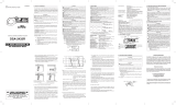
Power off the system under test.1.
Press the jaw opening trigger 2.
to open the jaws and clamp
them onto the conductor
under test.
NOTE: Do not clamp
over 2 or more wires
at the same time.
Irregular results
will occur.
Set the Rotary 3.
Dial to
or
position. AC or DC
mark is displayed.
Press the INRUSH 4.
button.
Power on the 5.
system under test.
The reading is 6.
displayed.
CAUTION Make a measurement
and press the MIN/MAX button after an
appropriate range is selected by the auto-
ranging function.
ZERO Function
(Cat. No. 2239-20 only)
AC Current / DC Current :
When the LCD doesn’t read
ZERO while the Jaws are closed,
press the ZERO Button to in-
dicate ZERO before starting a
measurement. With the jaws
closed and without clamping
them around a conductor, press
the ZERO key to zero adjust the
display.
The “ZERO” mark appears on
the LCD to indicate the ZERO
Function is activated.
°F / °C (Cat. No. 2238-20 only)
To switch between Fahrenheit or Celsius, press
the °F / °C button.
The MIN/MAX recording mode cap-
tures the minimum and maximum
input values.
Set the dial to to the desired measure-
ment function. Make a measurement
and press the MIN/MAX button. The
meter will capture the MIN and MAX
readings. Press the MIN/MAX button
to toggle between the captured MIN,
MAX and present readings. MAXMIN
ashes when the present reading is
displayed.
To exit and erase stored readings,
press the MIN/MAX button for two
seconds or change the dial.
If MIN/MAX is active, all function but-
tons are unavailable except HOLD.
CAUTION The Data Hold readings are
released when the meter enters Sleep Mode.
Over- ow indication
Any time the input exceeds the measuring range
“OL” or “-OL” is displayed.
Worklight LED ON/OFF
To turn the light on and off, pull the trigger.
Sleep Mode
Press
Press
0N0N
D
R
O
T
E
C
T
E
V
A
G
E
O
T
L
V
O
R
D
E
T
C
T
E
O
E
A
G
L
T
0FF 0FF
HOLD Function
Data Hold Function - Freezes the value on the
display. Press the “HOLD” button to freeze the
reading. The reading will be held regardless of
subsequent variation in input. HOLD is displayed
with the reading. To exit Data Hold mode, press
the HOLD button again. Hold is not available when
using the Inrush Function.
MIN/MAX Function
The clamp meter is automatically powered off in
about 20 min after the last Rotary Dial or button
operation. To reset, rotate the Rotary Dial or pull the
trigger. If the display is still blank when a new Rotary
Dial setting is selected, charge the battery pack.
To disable the sleep function, turn the tool off. Press
and hold the HOLD button and turn on the meter.
After the meter "beeps", release the HOLD button.
The meter will beep again and the clock symbol
will be removed from the display.
The clamp meter does use battery power in sleep
mode. Be sure to switch the tool to OFF to conserve
battery power.
DANGER To avoid electrical shock:
Never make measurement on a circuit in
which voltage over 1000V exists.
FIVE YEAR TOOL
LIMITED WARRANTY
MILWAUKEE Test & Measurement Products (includ-
ing bare tool, li-ion battery pack(s) and battery char-
ger but excluding alkaline batteries) are warranted
to the original purchaser only to be free from defects
in material and workmanship. Subject to certain
exceptions, MILWAUKEE will repair or replace any
part on this product which, after examination, is deter-
mined by MILWAUKEE to be defective in material or
workmanship for a period of ve (5) years* after the
date of purchase. Return the Test & Measurement
tool and a copy of proof of purchase to the nearest
Milwaukee Electric Tool Corporation - factory Service
Center. This warranty does not apply to damage that
MILWAUKEE determines to be from repairs made or
attempted by anyone other than MILWAUKEE autho-
rized personnel, misuse, alterations, abuse, normal
wear and tear, lack of maintenance, or accidents.
*The warranty period for the LITHIUM-ION battery
pack that ships with the Test & Measurement tool is
two (2) years from the date of purchase. *Alkaline
battery that ships with Test & Measurement tool is
separately warranted by the battery manufacturer.
*The warranty period for a NON-CONTACT VOLT-
AGE DETECTOR – 2201 20 is one (1) year from
the date of purchase.
Warranty Registration is not necessary to obtain
the applicable warranty on MILWAUKEE product.
The manufacturing date of the product will be used
to determine the warranty period if no proof of
purchase is provided at the time warranty service
is requested.
ACCEPTANCE OF THE EXCLUSIVE REPAIR
AND REPLACEMENT REMEDIES DESCRIBED
HEREIN IS A CONDITION OF THE CONTRACT
FOR THE PURCHASE OF EVERY MILWAUKEE
PRODUCT. IF YOU DO NOT AGREE TO THIS
CONDITION, YOU SHOULD NOT PURCHASE THE
PRODUCT. IN NO EVENT SHALL MILWAUKEE
BE LIABLE FOR ANY INCIDENTAL, SPECIAL,
CONSEQUENTIAL OR PUNITIVE DAMAGES, OR
FOR ANY COSTS, ATTORNEY FEES, EXPENSES,
LOSSES OR DELAYS ALLEGED TO BE AS A CON-
SEQUENCE OF ANY DAMAGE TO, FAILURE OF,
OR DEFECT IN ANY PRODUCT INCLUDING, BUT
NOT LIMITED TO, ANY CLAIMS FOR LOSS OF
PROFITS. THIS WARRANTY IS EXCLUSIVE AND
IN LIEU OF ALL OTHER WARRANTIES OR CON-
DITIONS, WRITTEN OR ORAL, EXPRESSED OR
IMPLIED. WITHOUT LIMITING THE GENERALITY
OF THE FOREGOING, MILWAUKEE DISCLAIMS
ANY IMPLIED WARRANTY OF MERCHANTABIL-
ITY OR FITNESS FOR A PARTICULAR USE OR
PURPOSE, AND ALL OTHER WARRANTIES.
This warranty applies to product sold in the U.S.A.,
Canada and Mexico only.
ACCESSORIES
For a complete listing of accessories refer to your
MILWAUKEE Electric Tool catalog or go online to
www.milwaukeetool.com. To obtain a catalog, con-
tact your local distributor or a service center listed
on the back cover of this operator’s manual.
WARNING Always remove battery
pack before changing or removing acces-
sories. Only use accessories specifically
recommended for this tool. Others may be
hazardous.
Maintaining Tool
Keep your tool, battery pack and charger in good
repair by adopting a regular maintenance program.
After six months to one year, depending on use,
return the tool, battery pack and charger to a
MILWAUKEE service facility service.
If the tool does not start or operate at full power
with a fully charged battery pack, clean the contacts
on the battery pack. If the tool still does not work
properly, return the tool, charger and battery pack,
to a MILWAUKEE service facility for repairs.
MAINTENANCE
Cleaning
Clean dust and debris from charger and tool vents.
Keep tool handles clean, dry and free of oil or grease.
Use only mild soap and a damp cloth to clean the
tool, battery pack and charger since certain cleaning
agents and solvents are harmful to plastics and other
insulated parts. Some of these include gasoline,
turpentine, lacquer thinner, paint thinner, chlorinated
cleaning solvents, ammonia and household deter-
gents containing ammonia. Never use ammable or
combustible solvents around tools.
Repairs
For repairs, return the tool, battery pack and char-
ger to the nearest service center listed on the back
cover of this operator's manual.
WARNING To reduce the risk of per-
sonal injury and damage, never immerse your
tool, battery pack or charger in liquid or allow
a liquid to ow inside them.
WARNING To reduce the risk of injury,
always unplug the charger and remove the
battery pack from the charger or tool before
performing any maintenance. Never disas-
semble the tool, battery pack or charger.
Contact a MILWAUKEE service facility for
ALL repairs.
28
MILWAUKEE ELECTRIC TOOL CORPORATION
13135 West Lisbon Road • Brook eld, Wisconsin, U.S.A. 53005
58-14-2238d2 8/09 Printed in China
UNITED STATES - MILWAUKEE Service
MILWAUKEE prides itself in producing a premium
quality product that is NOTHING BUT HEAVY DUTY
®
.
Your satisfaction with our products is very impor-
tant to us! If you encounter any problems with the
operation of this tool, or you would like to locate the
factory Service/Sales Support Branch or authorized
service station nearest you, please call...
Canada - Service MILWAUKEE
MILWAUKEE est er de proposer un produit de pre-
mière qualité NOTHING BUT HEAVY DUTY
®
. Votre satisfac-
tion est ce qui compte le plus!
En cas de problèmes d’utilisation de l’outil ou pour loca-
liser le centre de service/ventes ou le centre d’entretien
le plus proche, appelez le...
416.439.4181
fax: 416.439.6210
Milwaukee Electric Tool (Canada) Ltd
755 Progress Avenue
Scarborough, Ontario M1H 2W7
Notre réseau national de distributeurs agréés se
tient à votre disposition pour fournir l’aide technique,
l’outillage et les accessoires nécessaires. Composez
le 416.439.4181 pour obtenir les noms et adresses
des revendeurs les plus proches ou bien consultez la
section «Où acheter» sur notre site web à l’adresse
www.milwaukeetool.com
MEXICO - Soporte de Servicio
MILWAUKEE
1-800-SAWDUST
(1.800.729.3878)
Monday-Friday
7:00 AM - 6:30 PM
Central Time
or visit our website at
www.milwaukeetool.com
Additionally, we have a nationwide network of
authorized Distributors ready to assist you with
your tool and accessory needs. Check your “Yellow
Pages” phone directory under “Tools-Electric” for
the names & addresses of those nearest you or see
the 'Where To Buy' section of our website.
Contact our Corporate After Sales Service
Technical Support about ...
•Technical Questions
•Service/Repair Questions
•Warranty
call: 1-800-SAWDUST
fax: 1.800.638.9582
Register your tool online at
www.milwaukeetool.com and...
receive important noti cations regarding
your purchase
ensure that your tool is protected under the
warranty
• become a HEAVY DUTY club member
For service information, use the 'Service Center
Search' icon found in the 'Parts & Service' section.
Herramientas Alerka
Dr. Andrade 140 Local B, Col. Doctores
Delegación Cuauhtemoc, México D.F.
Telefono sin costo 01 800 832 1949
www.ttigroupmexico.com
Adicionalmente, tenemos una red nacional de distribui-
dores autorizados listos para ayudarle con su herramienta
y sus accesorios. Por favor, llame al 01 800 832 1949 para
obtener los nombres y direcciones de los más cercanos
a usted, o consulte la sección ‘Where to buy’ (Dónde
comprar) de nuestro sitio web en
www.ttigroupmexico.com
Registre su herramienta en línea, en
www.ttigroupmexico.com y...
• reciba importantes avisos sobre su compra
• asegúrese de que su herramienta esté
protegida por la garantía
• conviértase en integrante de Heavy Duty
  • Page 1 1
  • Page 2 2
  • Page 3 3
  • Page 4 4
  • Page 5 5
  • Page 6 6
  • Page 7 7
  • Page 8 8
  • Page 9 9
  • Page 10 10
  • Page 11 11
  • Page 12 12
  • Page 13 13
  • Page 14 14
  • Page 15 15

Milwaukee 2238-20 User manual

Category
Multimeters
Type
User manual

Ask a question and I''ll find the answer in the document

Finding information in a document is now easier with AI